EP0087313A2 - Vorrichtung zur Flammenfärbung - Google Patents
Vorrichtung zur Flammenfärbung Download PDFInfo
- Publication number
- EP0087313A2 EP0087313A2 EP83300904A EP83300904A EP0087313A2 EP 0087313 A2 EP0087313 A2 EP 0087313A2 EP 83300904 A EP83300904 A EP 83300904A EP 83300904 A EP83300904 A EP 83300904A EP 0087313 A2 EP0087313 A2 EP 0087313A2
- Authority
- EP
- European Patent Office
- Prior art keywords
- substrate
- burner
- flame
- emitter
- barrel
- Prior art date
- Legal status (The legal status is an assumption and is not a legal conclusion. Google has not performed a legal analysis and makes no representation as to the accuracy of the status listed.)
- Granted
Links
Images
Classifications
-
- G—PHYSICS
- G08—SIGNALLING
- G08B—SIGNALLING OR CALLING SYSTEMS; ORDER TELEGRAPHS; ALARM SYSTEMS
- G08B5/00—Visible signalling systems, e.g. personal calling systems, remote indication of seats occupied
- G08B5/40—Visible signalling systems, e.g. personal calling systems, remote indication of seats occupied using smoke, fire or coloured gases
-
- F—MECHANICAL ENGINEERING; LIGHTING; HEATING; WEAPONS; BLASTING
- F23—COMBUSTION APPARATUS; COMBUSTION PROCESSES
- F23M—CASINGS, LININGS, WALLS OR DOORS SPECIALLY ADAPTED FOR COMBUSTION CHAMBERS, e.g. FIREBRIDGES; DEVICES FOR DEFLECTING AIR, FLAMES OR COMBUSTION PRODUCTS IN COMBUSTION CHAMBERS; SAFETY ARRANGEMENTS SPECIALLY ADAPTED FOR COMBUSTION APPARATUS; DETAILS OF COMBUSTION CHAMBERS, NOT OTHERWISE PROVIDED FOR
- F23M11/00—Safety arrangements
- F23M11/04—Means for supervising combustion, e.g. windows
- F23M11/045—Means for supervising combustion, e.g. windows by observing the flame
Definitions
- the present invention relates to techniques and devices for rendering a flame visible.
- additives can degrade the performance of a burner by clogging the small orifice where the fuel is expelled.
- some additives can cause smoke.
- the present invention is directed to an article with these features.
- the article comprises two elements, a colorant emitter and a substrate or carrier that supports the colorant emitter.
- the colorant emitter can be a substance that is capable of emitting a material that provides visible light when the colorant emitter is placed in the flame.
- a suitable colorant emitter is a sodium salt such as sodium chloride, which when heated sufficiently ionizes to produce sodium ions which emit a visible yellow light, which can be easily seen against a blue sky or other brightly lit background.
- the substrate which carries the ion emitter is adapted for placement on a burner barrel with an emitter portion of the substrate extending into the flame.
- the substrate constitutes a material that is mechanically and thermally stable even when placed in a very hot flame.
- a preferred substrate is stainless steel mesh formed into a generally cylindrical shape for placement on a burner barrel, either inside the burner barrel or on the outside of the burner barrel, with an interference fit therebetween.
- An emitting portion of the substrate which has the ion emitter thereon is within or proximate to the flame.
- the colorant emitter be at a temperature approaching the flame temperature.
- conductive losses from the substrate, and particularly the emitter portion of the substrate are minimized. This can be accomplished by using a substrate that is longitudinally fluted to minimize contact between the substrate and the barrel.
- the substrate can have means for decreasing heat conduction from the emitting portion to the remainder of the substrate.
- Such means can be cut out portions separating the emitting portion of the substrate from the remainder of the substrate.
- This flame coloring device is versatile, reliable, and long-lived, having been demonstrated to color flames for times in excess of five hours. It is inexpensive and disposable, and renders a dangerous flame visible so that it can be used in safety.
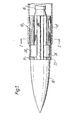
- a burner 10 is provided with a flame coloring device 12 according to the present invention.
- the device 12 can be used with a variety of burners for a variety of fuels, including liquid and gaseous fuels such as propane, acetylene, butane, methane, gasoline, and other hydrocarbon fuels. These fuels generally have a flame temperature in the order of 4,000°F to 4,500°F(2205-2483°C).
- the burner 10 has a cylindrical barrel 14, a nozzle 16 for the fuel, and when operating, produces a flame 18 that is conical within the barrel 14 and generally cylindrical beyond the barrel.
- the burner barrel 14 can be of a material such as brass or stainless steel. Barrels tyically have outer diameters in the order from about one half to about two inches (1.27-5cm).
- the device 12 comprises a carrier or substrate which carries a colorant emitter.
- the colorant emitter is a solid material that is capable of emitting visible light when placed in the flame.
- a suitable colorant emitter is one that when heated to the flame temperature, emits ions that emit visible light.
- the colorant emitter produces visible light at temperatures less than about 4,000°F(2205°C).At such elevated temperatures the solid emitter may become molten but in such event the substrate employed should be such that the molten emitter is retained on the substrate.
- Exemplary materials that can color a flame are potassium, rubidium, and cesium compounds (violet); copper chloride, copper bromide, lead, arsenic, and selenium compounds (blues); barium, antimony, and zinc compounds (greens); lithium, strontium, and calcium compounds (reds); and sodium compounds (yellow).
- potassium, rubidium, and cesium compounds violet
- copper chloride, copper bromide, lead, arsenic, and selenium compounds blues
- barium, antimony, and zinc compounds greens
- lithium, strontium, and calcium compounds reds
- sodium compounds yellow
- Preferred materials are sodium, lithium, and copper salts, with the sodium salts being most preferred because they provide a highly visible yellow color. Yellow is a desirable color when working out of doors, because it contrasts with the blue sky.
- the preferred sodium compound is sodium chloride.
- the substrate carries the colorant emitter. Because the substrate is in close proximity, and preferably within the flame, it needs to be thermally and mechanically stable at the temperature of the flame. Suitable materials for the substrate are stainless steel, carbon, low carbon steel, Hastelloy", titanium, tungston, and molybdenum. Stainless steel is the preferred material because of its mechanical strength at high temperatures, its relatively poor thermal heat transfer characteristics, easy formability, and oxidation resistance.
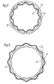
- the substrate is generally cylindrical in shape as shown in the figures.
- the term cylindrical as used herein includes tubular substrates and substrates which are not necessarily circular in cross-section but which can be of other suitable configurations such as oval, hexagonal or the like to conform to the shape of the barrel.
- the substrate has a diameter that provides an interference fit with the barrel 14 of the burner 10.
- the device 12 can be placed on the inside of the barrel 14 as shown in Figure 1, in which case the outer diameter of the device 12 should be about 0.03 inch (0.076cm) greater than the inside diameter of the barrel 14.
- the device 12 can be placed on the outside of the barrel 14, in which case the inside diameter of the device 12 should inch greater than the inside diameter of the barrel 14.
- the device 12 can be placed on the outside of the barrel 14, in which case the inside diameter of the device 12 should be about 0.03 inch (0.076cm) smaller than the outside diameter of the barrel 14. Placing the device on the outside of the barrel is particularly advantageous when the barrel has a relatively small inside diameter. In either case, an interference fit is provided between the device 12 on the burner 10. If desired, means other than an interference fit can be provided to secure the substrate to the barrel of the burner.
- the substrate can, for example, be clamped or bolted to the barrel.
- An advantage of having a cylindrical flame coloring device is that the entire periphery of the flame is colored, while the flame itself remains relatively undisturbed.
- the substrate is in a form which provides a large surface area with a small volume of material, and thus preferably is mesh-like.
- a mesh configuration allows the substrate to be quickly heated, yet provides a large surface area from which a colorant can be emitted into the flame. Further, mesh allows oxygen to reach the flame for burning of the fuel. Another advantage of mesh is that it has a relatively low thermal conductivity, and thus dissipates only small amounts of heat from the flame. Further, mesh is easy to form.
- the mesh To form the mesh into cylinder, it is rolled into the desired diameter, from about one-half to about two inches (1.27-5cm),and the ends are spot-welded together.
- the mesh size can be from about 40 to about 80, with smaller mesh sizes having an advantage that small wires can be used, and thus little heat is lost through conduction.
- the substrate be a poor conductor of heat. This allows the portion of the substrate in contact with the flame to be heated to a high temperature to maximize the amount of ions emitting visible light to maximize the intensity of the light.
- the use of stainless steel, which is a relatively poor thermal conductor, and a mesh design which minimizes heat losses by thermal conduction, is desirable.
- the substrate preferably is fluted, i.e. has a plurality of spaced apart longitudinal or axial grooves 20.
- the grooves can be circumferential.
- the surface area of the contact between the barrel 14 and the device 12 is substantially reduced as compared to a device 12 that is perfectly cylindrical.
- the device 12 being generally cylindrical, there is also included a device having such a fluted structure.
- the device extends beyond the end of the burner by about 1/2 inch (1.27cm) and extends into the barrel 14 for a distance of about 1-1/2 inches (3.81cm).
- the device it is possible for the device to not extend beyond the end of the barrel, as long as the colorant emitter can be heated to a sufficiently high temperature to provide a visible flame.
- the device 12 includes an end portion or emitting portion 22 that becomes red hot in a flame.
- means are provided for decreasing the heat conduction from the emitting portion to the remainder of the device.
- Such means can be cut-outs or spaces 24 in the mesh. These spaces 24 minimize heat conduction from the emitting portion to the remainder of the device.
- the colorant emitter can be placed on the substrate by a variety of techniques.
- the substrate can be dipped into molten color emitter, i.e. molten NaCl.
- molten color emitter i.e. molten NaCl.
- a concentrated aqueous solution of the colorant can be allowed to dry on the substrate.
- the colorant emitter can be incorporated into a resin such as epoxy resin, which can be applied to the substrate, and then cured resin can be burned off.
- the flame coloring device of the present invention has significant advantages. Because of the low heat conductivity of the substrate, and the separation of the emitting portion from the remainder of the device, the colorant emitter becomes hot very quickly. Thus, the flame becomes visible very quickly, in the order of seconds.
- the device is easy to use. It is inexpensive, simple to form, and minimizes interference with the flame. No complicated attachment mechanism is required to secure the device to a burner.
- the device provides a colored flame for many hours, in excess of five hours.
- Another advantage of the present invention is that the fuel itself is unaffected. Thus, the user has a choice of using the device or not using the device.
- the device has no moving parts, and thus is dependable and requires no maintenance.
Landscapes
- Engineering & Computer Science (AREA)
- General Engineering & Computer Science (AREA)
- Chemical & Material Sciences (AREA)
- General Physics & Mathematics (AREA)
- Combustion & Propulsion (AREA)
- Mechanical Engineering (AREA)
- Physics & Mathematics (AREA)
- Non-Portable Lighting Devices Or Systems Thereof (AREA)
- Glass Compositions (AREA)
- Developing Agents For Electrophotography (AREA)
- Special Wing (AREA)
- Lighters Containing Fuel (AREA)
- Control Of Combustion (AREA)
Priority Applications (1)
| Application Number | Priority Date | Filing Date | Title |
|---|---|---|---|
| AT83300904T ATE20140T1 (de) | 1982-02-23 | 1983-02-22 | Vorrichtung zur flammenfaerbung. |
Applications Claiming Priority (2)
| Application Number | Priority Date | Filing Date | Title |
|---|---|---|---|
| US06/351,676 US4472135A (en) | 1982-02-23 | 1982-02-23 | Flame coloring device |
| US351676 | 1982-02-23 |
Publications (3)
| Publication Number | Publication Date |
|---|---|
| EP0087313A2 true EP0087313A2 (de) | 1983-08-31 |
| EP0087313A3 EP0087313A3 (en) | 1984-05-02 |
| EP0087313B1 EP0087313B1 (de) | 1986-05-28 |
Family
ID=23381887
Family Applications (1)
| Application Number | Title | Priority Date | Filing Date |
|---|---|---|---|
| EP83300904A Expired EP0087313B1 (de) | 1982-02-23 | 1983-02-22 | Vorrichtung zur Flammenfärbung |
Country Status (7)
| Country | Link |
|---|---|
| US (1) | US4472135A (de) |
| EP (1) | EP0087313B1 (de) |
| JP (1) | JPS58160709A (de) |
| AT (1) | ATE20140T1 (de) |
| CA (1) | CA1197768A (de) |
| DE (1) | DE3363659D1 (de) |
| GB (1) | GB2115134B (de) |
Cited By (2)
| Publication number | Priority date | Publication date | Assignee | Title |
|---|---|---|---|---|
| EP0284701A1 (de) * | 1987-04-03 | 1988-10-05 | Ln Industries S.A. | Gasbrenner |
| EP1111300A3 (de) * | 1999-12-20 | 2002-07-24 | Lerchner, Leonhard | Leuchtvorrichtung |
Families Citing this family (9)
| Publication number | Priority date | Publication date | Assignee | Title |
|---|---|---|---|---|
| JPH0161555U (de) * | 1987-10-02 | 1989-04-19 | ||
| US4992041A (en) * | 1989-11-13 | 1991-02-12 | Gas Research Institute | Method and apparatus for producing a wood-like flame appearance from a fireplace-type gas burner |
| CA2162972C (en) * | 1994-11-16 | 2000-02-01 | Hideo Mifune | Flame reaction member for gas combustion appliances and a process for producing the same |
| US6250856B1 (en) | 1997-02-28 | 2001-06-26 | Kabushiki Kaisha Miyanaga | Quick attachment structure for drill shank |
| DE19961548A1 (de) * | 1999-12-20 | 2001-06-21 | Wedenig Albin | Dekorative Flammenfärbungen und Leuchtmittel |
| CA2552492C (en) * | 2005-07-19 | 2010-06-01 | Cfm U.S. Corporation | Heat activated air shutter for fireplace |
| CN101037582A (zh) * | 2007-01-23 | 2007-09-19 | 郑达 | 焰色反应材料及其火焰反应部件 |
| FI124635B (fi) * | 2008-04-14 | 2014-11-14 | Heiko Romu | Matalaenerginen liekinheitin |
| US20100307049A1 (en) * | 2009-06-06 | 2010-12-09 | Ta-Chun Peng | Liquid Fuel for a Colored Flame |
Family Cites Families (17)
| Publication number | Priority date | Publication date | Assignee | Title |
|---|---|---|---|---|
| GB190212742A (en) * | 1902-06-04 | 1902-10-23 | Eduard Oelbermann | Process and Contrivance for Attaining a Coloured Flame with Candles, Bucket or Fairy Lamps, and the like. |
| US808513A (en) * | 1904-12-13 | 1905-12-26 | Truman G Palmer | Incandescent gas-lamp. |
| GB170138A (en) * | 1920-07-27 | 1921-10-20 | Alfred Kendal Toulmin Smith | Improvements in luminous signalling devices and the like |
| GB216968A (en) * | 1923-03-17 | 1924-06-12 | Thomas Terrell Junior | Improvements in or relating to incandescent mantles |
| US1829001A (en) * | 1927-12-23 | 1931-10-27 | Geromanos Hercules Wallace | Spectra demonstrator |
| US2270443A (en) * | 1941-03-15 | 1942-01-20 | Jares Joseph | Flame production and control |
| US2809101A (en) * | 1954-05-05 | 1957-10-08 | Turner Brass Works | Halide leak detector |
| GB988779A (en) * | 1961-01-24 | 1965-04-14 | Auergesellschaft Gmbh | Improvements in or relating to incandescent gas mantles |
| GB988799A (en) * | 1962-09-17 | 1965-04-14 | Radyne Ltd | Improvements in or relating to radio frequency heating equipment |
| US3187523A (en) * | 1963-10-07 | 1965-06-08 | Leggitt S H Co | Flame shaper and luminosity control |
| US3385647A (en) * | 1965-08-30 | 1968-05-28 | Basic Products Corp | Method of making a hydrogen flame visible |
| US3504976A (en) * | 1966-05-04 | 1970-04-07 | Beckman Instruments Inc | Process and apparatus for the detection of halogens |
| US3468615A (en) * | 1967-11-03 | 1969-09-23 | Worcester Gurdon S | Colored flame combustion device |
| GB1272751A (en) * | 1968-06-18 | 1972-05-03 | Kathleen Mary Likeman | Improvements in the burners of gas cookers and portable cooking appliances |
| US3816062A (en) * | 1972-09-26 | 1974-06-11 | Pont S Soc Du | Burner heads of liquefied fuel gas lighters |
| FR2208404A5 (en) * | 1972-11-28 | 1974-06-21 | Cangardel Jean | Candle with coloured flame - has central rod of metaldehyde and a metal cpd. which gives rise to the flame colour |
| GB2049912B (en) * | 1979-05-21 | 1983-06-15 | Auergesellschaft Gmbh | Illumination sources |
-
1982
- 1982-02-23 US US06/351,676 patent/US4472135A/en not_active Expired - Fee Related
-
1983
- 1983-02-22 GB GB08304932A patent/GB2115134B/en not_active Expired
- 1983-02-22 AT AT83300904T patent/ATE20140T1/de not_active IP Right Cessation
- 1983-02-22 EP EP83300904A patent/EP0087313B1/de not_active Expired
- 1983-02-22 DE DE8383300904T patent/DE3363659D1/de not_active Expired
- 1983-02-22 CA CA000422118A patent/CA1197768A/en not_active Expired
- 1983-02-23 JP JP58030159A patent/JPS58160709A/ja active Pending
Cited By (2)
| Publication number | Priority date | Publication date | Assignee | Title |
|---|---|---|---|---|
| EP0284701A1 (de) * | 1987-04-03 | 1988-10-05 | Ln Industries S.A. | Gasbrenner |
| EP1111300A3 (de) * | 1999-12-20 | 2002-07-24 | Lerchner, Leonhard | Leuchtvorrichtung |
Also Published As
| Publication number | Publication date |
|---|---|
| GB8304932D0 (en) | 1983-03-23 |
| GB2115134A (en) | 1983-09-01 |
| JPS58160709A (ja) | 1983-09-24 |
| US4472135A (en) | 1984-09-18 |
| CA1197768A (en) | 1985-12-10 |
| ATE20140T1 (de) | 1986-06-15 |
| EP0087313B1 (de) | 1986-05-28 |
| GB2115134B (en) | 1985-07-10 |
| EP0087313A3 (en) | 1984-05-02 |
| DE3363659D1 (en) | 1986-07-03 |
Similar Documents
| Publication | Publication Date | Title |
|---|---|---|
| US4472135A (en) | Flame coloring device | |
| US2504211A (en) | Production of colored flames | |
| US5281131A (en) | Selective emissive burner | |
| SE8902445L (sv) | Syrgasgenerator | |
| US2305561A (en) | Flash lamp | |
| US1930315A (en) | Flash lamp | |
| CA1194777A (en) | Underwater cutting tool | |
| US808513A (en) | Incandescent gas-lamp. | |
| US1923313A (en) | Illuminant burning with alpha multicolored flame | |
| US3468615A (en) | Colored flame combustion device | |
| US3393967A (en) | Light source | |
| Kim et al. | Long-duration transmission of information with infofuses | |
| Emetere et al. | A review on electrical bulbs and its improvement over time: Saving energy or life? | |
| US3516772A (en) | Opaque light source | |
| US3488130A (en) | Enhanced output light source | |
| Fortman et al. | Variations on the" Whoosh" Bottle Alcohol Explosion Demonstration Including Safety Notes | |
| US3481679A (en) | Incandescent light source | |
| JPS5661758A (en) | Fluorescent lamp | |
| JPS5684866A (en) | Discharging lamp incorporated with ballast | |
| HU209142B (en) | Colouring wick | |
| KR100887554B1 (ko) | 폭죽기능을 가진 양초 | |
| SU775520A1 (ru) | Излучающа горелка | |
| RU2128867C1 (ru) | Газоразрядная лампа низкого давления | |
| Hyde et al. | The quality of light from an illuminant as indicated by its color temperature | |
| SU1450012A1 (ru) | Лампа накаливани |
Legal Events
| Date | Code | Title | Description |
|---|---|---|---|
| PUAI | Public reference made under article 153(3) epc to a published international application that has entered the european phase |
Free format text: ORIGINAL CODE: 0009012 |
|
| 17P | Request for examination filed |
Effective date: 19830302 |
|
| AK | Designated contracting states |
Designated state(s): AT BE CH DE FR IT LI NL SE |
|
| PUAL | Search report despatched |
Free format text: ORIGINAL CODE: 0009013 |
|
| AK | Designated contracting states |
Designated state(s): AT BE CH DE FR IT LI NL SE |
|
| ITF | It: translation for a ep patent filed | ||
| GRAA | (expected) grant |
Free format text: ORIGINAL CODE: 0009210 |
|
| AK | Designated contracting states |
Kind code of ref document: B1 Designated state(s): AT BE CH DE FR IT LI NL SE |
|
| PG25 | Lapsed in a contracting state [announced via postgrant information from national office to epo] |
Ref country code: AT Effective date: 19860528 |
|
| REF | Corresponds to: |
Ref document number: 20140 Country of ref document: AT Date of ref document: 19860615 Kind code of ref document: T |
|
| REF | Corresponds to: |
Ref document number: 3363659 Country of ref document: DE Date of ref document: 19860703 |
|
| ET | Fr: translation filed | ||
| PLBE | No opposition filed within time limit |
Free format text: ORIGINAL CODE: 0009261 |
|
| STAA | Information on the status of an ep patent application or granted ep patent |
Free format text: STATUS: NO OPPOSITION FILED WITHIN TIME LIMIT |
|
| 26N | No opposition filed | ||
| ITTA | It: last paid annual fee | ||
| PGFP | Annual fee paid to national office [announced via postgrant information from national office to epo] |
Ref country code: SE Payment date: 19940216 Year of fee payment: 12 |
|
| PGFP | Annual fee paid to national office [announced via postgrant information from national office to epo] |
Ref country code: DE Payment date: 19940224 Year of fee payment: 12 Ref country code: CH Payment date: 19940224 Year of fee payment: 12 |
|
| PGFP | Annual fee paid to national office [announced via postgrant information from national office to epo] |
Ref country code: BE Payment date: 19940408 Year of fee payment: 12 |
|
| EAL | Se: european patent in force in sweden |
Ref document number: 83300904.6 |
|
| PGFP | Annual fee paid to national office [announced via postgrant information from national office to epo] |
Ref country code: FR Payment date: 19950210 Year of fee payment: 13 |
|
| PG25 | Lapsed in a contracting state [announced via postgrant information from national office to epo] |
Ref country code: SE Effective date: 19950223 |
|
| PG25 | Lapsed in a contracting state [announced via postgrant information from national office to epo] |
Ref country code: LI Effective date: 19950228 Ref country code: CH Effective date: 19950228 Ref country code: BE Effective date: 19950228 |
|
| PGFP | Annual fee paid to national office [announced via postgrant information from national office to epo] |
Ref country code: NL Payment date: 19950228 Year of fee payment: 13 |
|
| BERE | Be: lapsed |
Owner name: RAYCHEM CORP. Effective date: 19950228 |
|
| PG25 | Lapsed in a contracting state [announced via postgrant information from national office to epo] |
Ref country code: DE Effective date: 19951101 |
|
| EUG | Se: european patent has lapsed |
Ref document number: 83300904.6 |
|
| PG25 | Lapsed in a contracting state [announced via postgrant information from national office to epo] |
Ref country code: NL Effective date: 19960901 |
|
| PG25 | Lapsed in a contracting state [announced via postgrant information from national office to epo] |
Ref country code: FR Effective date: 19961031 |
|
| NLV4 | Nl: lapsed or anulled due to non-payment of the annual fee |
Effective date: 19960901 |
|
| REG | Reference to a national code |
Ref country code: FR Ref legal event code: ST |