EP0086352A2 - Tête de vissage - Google Patents
Tête de vissage Download PDFInfo
- Publication number
- EP0086352A2 EP0086352A2 EP83100564A EP83100564A EP0086352A2 EP 0086352 A2 EP0086352 A2 EP 0086352A2 EP 83100564 A EP83100564 A EP 83100564A EP 83100564 A EP83100564 A EP 83100564A EP 0086352 A2 EP0086352 A2 EP 0086352A2
- Authority
- EP
- European Patent Office
- Prior art keywords
- sleeve
- screwdriver
- clamping
- screw head
- screw
- Prior art date
- Legal status (The legal status is an assumption and is not a legal conclusion. Google has not performed a legal analysis and makes no representation as to the accuracy of the status listed.)
- Withdrawn
Links
Images


Classifications
-
- B—PERFORMING OPERATIONS; TRANSPORTING
- B25—HAND TOOLS; PORTABLE POWER-DRIVEN TOOLS; MANIPULATORS
- B25B—TOOLS OR BENCH DEVICES NOT OTHERWISE PROVIDED FOR, FOR FASTENING, CONNECTING, DISENGAGING OR HOLDING
- B25B21/00—Portable power-driven screw or nut setting or loosening tools; Attachments for drilling apparatus serving the same purpose
- B25B21/007—Attachments for drilling apparatus for screw or nut setting or loosening
-
- B—PERFORMING OPERATIONS; TRANSPORTING
- B25—HAND TOOLS; PORTABLE POWER-DRIVEN TOOLS; MANIPULATORS
- B25B—TOOLS OR BENCH DEVICES NOT OTHERWISE PROVIDED FOR, FOR FASTENING, CONNECTING, DISENGAGING OR HOLDING
- B25B23/00—Details of, or accessories for, spanners, wrenches, screwdrivers
- B25B23/0064—Means for adjusting screwing depth
Definitions
- the invention relates to a screw head according to the preamble of claim 1.
- Such a configuration is known from DE-PS 2 843 684, the screwdriver having a polygonal cross-section being seated in a central receptacle of the clamping sleeve adapted to the corner size of the screwdriver.
- the head surface of the screwdriver is supported on a thrust bearing ball, while against the polygonal surfaces of the screwdriver there are radial holes penetrating the clamping pin sleeve, which are pressed inwards by the inner wall of the coupling sleeve.
- there is an annular spring in front of the balls which snaps into notches in the corners of the screwdriver.
- the balls and the ring spring thus represent the clamping members fixing the screwdriver.
- the object of the invention is based on the object of designing a screw head of the required type in a technically more simple manner in such a way that the replacement of the screwdriver is easier to carry out and that, in addition to improved guidance, wear is reduced.
- the actuating sleeve acts on the end edge of the coupling sleeve, which in turn causes the disengagement after a corresponding relative displacement to the clamping pin sleeve.
- the actuating sleeve can be displaced against spring action, whereby it releases the clamping members for holding the screwdriver. In this position, the screwdriver slips out of the sleeve. The use of tools for replacing screwdrivers is therefore no longer necessary.
- a clamping sleeve displaced from the actuating sleeve and having a clamping ball, which presses on a polygonal surface of the screwdriver, can serve as clamping members, for example. If the actuating sleeve is displaced against spring action the coupling sleeve, clamping pin sleeve and the sleeve mounted in this remain in their starting position.
- One way to be able to replace the screwdriver is to move the actuating sleeve from its stop position to the coupling sleeve in the screwing direction.
- clamping pin sleeve is additionally supported by balls in the coupling sleeve, which balls are located on the screwdriver side of the coupling balls and engage in an annular groove in the shaft of the sleeve. Accordingly, the bearing balls lead to both axial and radial bearing of the clamping sleeve on the sleeve.
- the bottom surface of the receptacle has a height adjustment screw as a stop for the head surface of the screwdriver.
- Another advantage is the fact that a screw centering and / or retaining ring can be attached in front of the edge of the ring section. This allows the screws to be sufficiently firmly assigned to the screw head before screwing in, so that the screws can only be attached and turned using the screw head.
- a particularly favorable holder is that the screw retaining ring is equipped with a holding magnet which is located on the outside of a passage opening for the screwdriver.
- the variation in the screw-in depth can be carried out more easily and that no tensile forces in the screw-in direction on the actuating sleeve are effective for removing the screwdriver, actuating sleeves and the coupling sleeve are arranged so as to be adjustable in relation to one another, and the displacement of both parts beyond the uncoupling position releases the holder of the screwdriver.
- a major advantage of this solution is that the screw-in depth can now be varied without tools. To change the screw-in depth, only the actuating sleeve has to be screwed in or out correspondingly far into the coupling sleeve. No further action is required.
- the screw head Since there are no displacement forces in the screw-in direction to remove the screwdriver, the screw head is particularly suitable for use on drills and similar devices. If the screw head is not securely fastened to the drilling machine, it cannot happen that the screw head is pulled out of the holder when the actuating sleeve is moved. The actuating sleeve is now shifted into the release position in the direction of insertion of the screwdriver, specifically beyond the uncoupling position. This ensures that even the holder of the screwdriver is not relinquished in the uncoupling position.
- An advantageous embodiment consists in that the sleeve receiving the screwdriver cross-section is surrounded by a carrying sleeve for the one clamping member designed as a ball, which is spring-loaded in the screwing-in direction and receives the ball in the cavity of a wing protruding in the screwing-in direction, which is the second of one Clamping member, by the sleeve receiving the screwdriver cross-section holding sleeve is included on the outside, which is the actuating sleeve, the one shoulder has, which lies at a distance from a counter shoulder of the carrying sleeve.
- the carrying sleeve is only moved when the shoulder of the actuating sleeve acts on the counter shoulder. Once the decoupling position of the screw head has been reached, the actuating sleeve must be moved an additional way in order to move the carrying sleeve.
- the wing corresponds to a segment that forms the non-circular cross-section of the sleeve and the clamping surface of the clamping sleeve extends over the entire circumference of the inner flank.
- the wing lengthens the one flank of the receptacle and, on the other hand, this design brings the support sleeve on the sleeve to be non-rotatable. Installation is also facilitated.
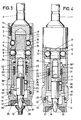
- the screw head has a clamping pin 1 which can be inserted into a chuck of a drilling machine or the like and which continues into a clamping pin sleeve 2.
- the latter has in its central area three radial bores 3 arranged in the same angular distribution for receiving coupling balls 4.
- a further three radial bores 5 are provided for receiving bearing balls 6.
- the aforementioned coupling balls 4 act together with longitudinally extending arcuate grooves 7 of the shaft 8 'of a sleeve 8 mounted in the clamping sleeve 2.
- Six such arcuate grooves 7 are arranged in the sleeve 8 with the same angular distribution, so that in every second one of these grooves 7 a coupling ball 4 is immersed, cf. in particular FIG. 5.
- the bearing balls 6, on the other hand, engage in an annular groove 9 in the shaft 8 'of the sleeve 8.
- the bearing balls 6 support the sleeve 8 on the one hand in the axial direction and on the other hand in the radial direction.
- a coupling sleeve 10 supporting the bearing balls 6 is guided on the clamping pin sleeve 2.
- the latter presses the coupling balls 4 into the grooves 7 with a zone 11 with a larger cross section.
- This position is maintained by a compression spring 12 which is supported on the zone 11 and is arranged on the inside of the coupling sleeve 10 and which in turn presses against a snap ring 13 at the upper end of the clamping pin sleeve 2.
- the coupling sleeve 10 experiences a stop limitation in the suspension direction in that it steps with an annular shoulder 14 against a collar 15 of the clamping pin sleeve.
- a central escape space 16 for the coupling balls 4 connects to the annular shoulder 14.
- the sleeve 8 is equipped at its free lower end with a central, polygonal receptacle 17.
- the corresponding polygonal shaft 18 'of a screwdriver 18 enters this.
- the blade part 18 ′′ of the same it is one for a Phillips screw 19.
- the insertion depth of the screwdriver 18 can be varied by a height adjustment screw 20 which is screwed into the bottom surface of the receptacle 17 and acts on the head surface 18111 of the screwdriver.
- a bushing 21 is guided in the longitudinal direction on the sleeve 8.
- One end of a compression spring 23 comes into contact with an upper radially inward collar 22 of the clamping sleeve 21, which in turn is supported on an outwardly directed shoulder 24 of the sleeve.
- the collet 21 is loaded in the upward direction.
- the clamping sleeve receives a limitation when the screwdriver 18 is not inserted by a snap ring 25 of the sleeve 8. According to FIGS.
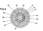
- an inclined clamping surface 26 of the clamping sleeve 21 acts in the inward direction on a clamping ball 28 arranged in a radial bore 27 of the sleeve 8, which counteracts a Polygonal surface of the screwdriver presses and thus captivates it in the receptacle 17.
- An actuating sleeve 29 is guided between the clamping sleeve 21 and the coupling sleeve 10 and has an annular section 30 lying in front of the end edge 10 'of the coupling sleeve 10.
- the inner end of the actuating sleeve 29 forms a collar 30 "which overlaps the collar 22 of the clamping sleeve 21. In the basic position illustrated in FIG. 2, the collar 30" lies flat against the collar 22, while the end edge 10 'of the coupling sleeve 10 is in front of that of the ring section 30 formed step 30 '.
- the ring section 30 With its lower free end, the ring section 30 forms an edge R surrounding the screwdriver 18.
- a screw centering retaining ring 31 sits in front of it.
- An inner ring groove 32 provided in the ring section 30 serves to fix the same, for receiving an annular spring 33 which is inserted into an outer groove 34 of the ring groove 33 Screw retaining ring 31 engages and fixes this.
- the retaining ring 31 carries a holding magnet 35 which is provided with a cavity 35 'which is adapted to the screw head 19'. The latter continues into a passage opening 36 for the screwdriver 18, which passage opening is aligned with an opening 37 of the retaining ring 31.
- the edge R placed on the component receiving the screw is advanced. Accordingly, the end face of the screw retaining ring 31 now represents the contacting edge R '.
- a space 38 extends between the collar 30 "of the actuating sleeve 29 and the lower end of the clamping pin sleeve 2, which allows a relative displacement of the actuating sleeve 29 with coupling sleeve 10 to the clamping pin sleeve 2.
- a screw 19 If a screw 19 is to be screwed in, it can be fixed to the blade 18 "of the screwdriver 18 by means of the holding magnet 35.
- the force flow runs from the clamping pin sleeve 2 to the sleeve 8 while taking the screwdriver 18, which screwed in the screw corresponding screw depth reached, the edge R 'touches the component, and with further screwing this leads to a relative displacement between the clamping sleeve 2 with sleeve 8 to the screw retaining ring 31 with actuating sleeve 29 and coupling sleeve 10.
- the coupling balls 4 get into the alternative space 16 Coupling sleeve 10, so that the coupling balls are controlled in the outward direction via the side flanks of the arcuate grooves 7, see FIG. 3 and dash-dotted lines in FIG. 5. Then the sleeve 8 is no longer taken with the screwdriver 18. This indicates to the user that the screw-in depth has been reached.
- the compression spring 12 compressed during the relative displacement can relax after removing the screw head and returns the coupling sleeve 10 with the actuating sleeve 29 to the starting position according to FIGS. 1 and 2.
- the ring section 30 provided with a cord must be grasped and the actuating sleeve 29 pushed in the screwing direction x.
- the clamping sleeve 21 is taken over the collar 30 "of the actuating sleeve 29.
- the clamping surface 26 releases the clamping ball 28 so that the screwdriver 18 can be removed.
- this removal can take place at the same time as the ring section 31 is removed.
- the coupling sleeve 10 does not change its position relative to the clamping pin sleeve 2 and accordingly to the sleeve 8.
- the previously tensioned compression spring 23 guides the clamping sleeve 21 and thus the actuating sleeve 29 into the basic position according to FIG. 2 back.
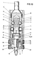
- the lower free end 8 ′′ of the sleeve 8 is stepped there in a step-like manner.
- the other end the latter finds a stop on an annular shoulder 41 of a carrying sleeve 42 which can be displaced on the sleeve 8.
- the annular shoulder 41 connects two different guide surfaces of the carrying sleeve 42.
- the stepped, offset end 42 'of the carrying sleeve 42 continues in a wing 43 projecting in the screwing direction.
- the latter is segmented in cross section in such a way that its inner flat surface 43 'is flush with a flank of the receptacle 17 with a cross section, cf.
- the end 8 "of the sleeve 8 is with a Provide corresponding recess 44 so that the wing 43 complements the circular cross-section of the end 8 "at the same height to form a circular shape.
- the length of the recess 44 is greater than the length of the wing 43.
- wing 43 there is a cavity 45 arranged transversely to the longitudinal direction of the carrying sleeve 42 for receiving a clamping ball 46. Its diameter is greater than the thickness of the wing 43 lying in the radial direction. A falling out of the clamping ball 46 from the cavity 45 is prevented by the shut-in Edge 47 prevented. However, it is ensured that the clamping ball 46 has sufficient play in the radial direction.
- Both the free end 8 "of the sleeve 8 and the wing 10 are encompassed by a clamping bush 48. This is clamped on the outer circumference of the sleeve end 8", in such a way that the wing 43 is not covered by this clamp seat but maintains its free mobility.
- the clamping bush 48 forms an inner clamping surface 49 which slopes in a wedge shape towards the free end and which cooperates with the clamping ball 46.
- the clamping surface 49 continues through a step into a cavity 50 which is adapted to the outer circumference of the stepped end 42 ′ of the carrying sleeve 42 while allowing the carrying sleeve 42 to move.
- the compression spring 23 causes the carrying sleeve 42 to be displaced counter to the insertion direction of the screwdriver.
- the wing 43 with its clamping ball 46 is displaced in the downward direction, the clamping ball 46 being supported on the clamping surface 49 and thereby exerting a clamping force on the shaft 18 'of the screwdriver 18, see FIGS. 7 and 8. If a tensile force occurs on the screwdriver 18, the clamping force increases.
- the coupling sleeve 10 which extends as far as the clamping sleeve 48, is equipped at the free end with an internal thread into which the external thread of an actuating sleeve 29 'engages.
- the latter is rotatably seated on the carrying sleeve 42 and clamping sleeve 48.
- the free end of the actuating sleeve 29 ' is shaped into a projecting ring section 30 provided with knurling which, with its lower free end, forms an edge R surrounding the screwdriver 18.
- a lock nut 50 runs on the external thread of the actuating sleeve 29 '.
- the lock nut 50 is clamped against the end face F of the coupling sleeve 10. Then the actuating sleeve 29 'does not inadvertently change its position relative to the coupling sleeve 10.
- a counter shoulder 53 is produced by the stepped end 42 'of the carrying sleeve 42, which in the basic position according to FIG. 7 lies at a distance from a shoulder 52 of the actuating sleeve 29'.
- the compression spring 12 compressed during the relative displacement can relax after removing the screw head from the component 51 and returns the coupling sleeve 10 with the actuating sleeve 29 'to the starting position according to FIG. 7.
- the actuating sleeve 29 'with the coupling sleeve 10 must be displaced beyond the uncoupling position in the direction of the arrow shown.
- the shoulder 52 of the actuating sleeve 29 ′ acts on the counter shoulder 53 of the carrying bush 42 and moves it into the position according to FIG. 10.
- the compression spring 23 is tensioned by the carrying bush 42, and the clamping ball 46 is carried along by the wing 43. As a result, it arrives from the clamping position between the clamping surface 49 of the clamping ring 48 and the shaft 18 '. The screwdriver 18 can then be easily removed.
- the compression spring 12 After release of the actuating sleeve 29 ', the compression spring 12 returns the coupling sleeve 10 to its stop position, while the compression spring 23 displaces the carrying sleeve 42 until its counter shoulder 53 acts on the facing end edge 48' of the clamping sleeve 48.
- the lock nut 50 forms with its surface facing the ring portion 30 the end edge 10 'of the coupling sleeve 10, whereby the adjustment of the actuating sleeve 29' is limited in one direction.
Landscapes
- Engineering & Computer Science (AREA)
- Mechanical Engineering (AREA)
- Details Of Spanners, Wrenches, And Screw Drivers And Accessories (AREA)
Applications Claiming Priority (4)
| Application Number | Priority Date | Filing Date | Title |
|---|---|---|---|
| DE3205118 | 1982-02-12 | ||
| DE19823205118 DE3205118C2 (de) | 1982-02-12 | 1982-02-12 | Schraubkopf mit einer Einrichtung zum selbsttätigen Auskuppeln des Schraubendrehers beim Erreichen einer bestimmten Einschraubtiefe |
| DE19823243388 DE3243388A1 (de) | 1982-11-24 | 1982-11-24 | Schraubkopf |
| DE3243388 | 1982-11-24 |
Publications (2)
| Publication Number | Publication Date |
|---|---|
| EP0086352A2 true EP0086352A2 (fr) | 1983-08-24 |
| EP0086352A3 EP0086352A3 (fr) | 1985-05-15 |
Family
ID=25799574
Family Applications (1)
| Application Number | Title | Priority Date | Filing Date |
|---|---|---|---|
| EP83100564A Withdrawn EP0086352A3 (fr) | 1982-02-12 | 1983-01-22 | Tête de vissage |
Country Status (2)
| Country | Link |
|---|---|
| EP (1) | EP0086352A3 (fr) |
| ES (1) | ES519716A0 (fr) |
Cited By (7)
| Publication number | Priority date | Publication date | Assignee | Title |
|---|---|---|---|---|
| EP0199869A1 (fr) * | 1985-04-18 | 1986-11-05 | Julien Jean Louis Lankry | Outils pour serrer ou desserer des fixations équipées de filets de vis |
| EP0302202A2 (fr) * | 1987-08-07 | 1989-02-08 | Fischerwerke Arthur Fischer GmbH & Co. KG | Outil pour la pose d'éléments de fixation |
| WO1996029182A1 (fr) * | 1995-03-21 | 1996-09-26 | Optigrip-Werkzeuge | Mandrin muni d'un systeme d'accouplement |
| WO2005000531A1 (fr) * | 2003-06-25 | 2005-01-06 | Vessel Industrial Co., Ltd. | Dispositif de support de meche |
| CN100371135C (zh) * | 2005-02-06 | 2008-02-27 | 陈河田 | 工具起子头夹持结构 |
| GB2529525A (en) * | 2014-07-15 | 2016-02-24 | Chervon Ip Ltd | Bit accessory and bit assembly |
| US20200086462A1 (en) * | 2016-12-08 | 2020-03-19 | Apex Brands, Inc. | Anti-marring bit holder |
Citations (3)
| Publication number | Priority date | Publication date | Assignee | Title |
|---|---|---|---|---|
| US1832123A (en) * | 1930-01-29 | 1931-11-17 | Black & Decker Mfg Co | Clutch release for portable power driven rotary tools |
| DE2843684A1 (de) * | 1978-10-06 | 1980-04-10 | Helfer & Co Kg Feinwerkbau | Kraftangetriebener schraubkopf |
| US4296656A (en) * | 1980-04-21 | 1981-10-27 | Illinois Tool Works Inc. | Driver bit attachment |
-
1983
- 1983-01-22 EP EP83100564A patent/EP0086352A3/fr not_active Withdrawn
- 1983-02-11 ES ES519716A patent/ES519716A0/es active Granted
Patent Citations (3)
| Publication number | Priority date | Publication date | Assignee | Title |
|---|---|---|---|---|
| US1832123A (en) * | 1930-01-29 | 1931-11-17 | Black & Decker Mfg Co | Clutch release for portable power driven rotary tools |
| DE2843684A1 (de) * | 1978-10-06 | 1980-04-10 | Helfer & Co Kg Feinwerkbau | Kraftangetriebener schraubkopf |
| US4296656A (en) * | 1980-04-21 | 1981-10-27 | Illinois Tool Works Inc. | Driver bit attachment |
Non-Patent Citations (1)
| Title |
|---|
| VDI-NACHRICHTEN, Band 12, Nr. 22 Oktober 25, 1958, Seite 3. "Einwegschrauber fur Stiftschrauben". * |
Cited By (13)
| Publication number | Priority date | Publication date | Assignee | Title |
|---|---|---|---|---|
| EP0199869A1 (fr) * | 1985-04-18 | 1986-11-05 | Julien Jean Louis Lankry | Outils pour serrer ou desserer des fixations équipées de filets de vis |
| EP0302202A2 (fr) * | 1987-08-07 | 1989-02-08 | Fischerwerke Arthur Fischer GmbH & Co. KG | Outil pour la pose d'éléments de fixation |
| EP0302202A3 (fr) * | 1987-08-07 | 1990-04-18 | Fischerwerke Arthur Fischer GmbH & Co. KG | Outil pour la pose d'éléments de fixation |
| WO1996029182A1 (fr) * | 1995-03-21 | 1996-09-26 | Optigrip-Werkzeuge | Mandrin muni d'un systeme d'accouplement |
| US6192776B1 (en) | 1995-03-21 | 2001-02-27 | Optigrip-Werkzeuge | Chuck with coupling |
| WO2005000530A1 (fr) * | 2003-06-25 | 2005-01-06 | Vessel Industrial Co., Ltd. | Dispositif de maintien de meche |
| WO2005000531A1 (fr) * | 2003-06-25 | 2005-01-06 | Vessel Industrial Co., Ltd. | Dispositif de support de meche |
| US7261023B2 (en) | 2003-06-25 | 2007-08-28 | Vessel Industrial Co., Ltd. | Bit holder device |
| CN100371135C (zh) * | 2005-02-06 | 2008-02-27 | 陈河田 | 工具起子头夹持结构 |
| GB2529525A (en) * | 2014-07-15 | 2016-02-24 | Chervon Ip Ltd | Bit accessory and bit assembly |
| GB2529525B (en) * | 2014-07-15 | 2020-09-16 | Chervon (Hk) Ltd | Bit accessory and bit assembly |
| US20200086462A1 (en) * | 2016-12-08 | 2020-03-19 | Apex Brands, Inc. | Anti-marring bit holder |
| US11440167B2 (en) * | 2016-12-08 | 2022-09-13 | Apex Brands, Inc. | Anti-marring bit holder |
Also Published As
| Publication number | Publication date |
|---|---|
| EP0086352A3 (fr) | 1985-05-15 |
| ES8400915A1 (es) | 1983-12-01 |
| ES519716A0 (es) | 1983-12-01 |
Similar Documents
| Publication | Publication Date | Title |
|---|---|---|
| EP0134975B1 (fr) | Mandrin pour la fixation de pièces d'un outil, notamment d'un tournevis | |
| DE19505754C1 (de) | Stanzstempeleinheit | |
| DE3610749C2 (fr) | ||
| DE3030909C2 (fr) | ||
| EP0528262B1 (fr) | Dispositif mécanique de serrage | |
| DE102011106421B3 (de) | Schaftwerkzeug, Werkzeughalterung für ein Schaftwerkzeug sowie Reduzierhülse für eine Werkzeughalterung | |
| DE10031027B4 (de) | Spannmechanismus für eine Spindel in einer Werkzeugmaschine | |
| DE2227309A1 (de) | Zwischenstueck fuer werkzeughalter | |
| WO1984003917A1 (fr) | Dispositif de fixation de goujons | |
| DE102016100933B4 (de) | Montagewerkzeug, dessen Verwendung und Verfahren zur Befestigung eines Gewindeeinsatzes | |
| DE3243389A1 (de) | Spannfutter fuer werkzeug-einsatzstuecke, insbesondere schraubendreherbits | |
| DE3031216C2 (de) | Spannfutter für Gewindebohrer | |
| EP0275441B1 (fr) | Dispositif de serrage | |
| EP0086352A2 (fr) | Tête de vissage | |
| DE2605310A1 (de) | Bolzenelement zur befestigung in einer sockelbohrung | |
| DE1602760C3 (de) | Einstellbarer Werkzeugeinsatz | |
| DE69215905T2 (de) | Spannvorrichtung für fräser oder ähnliche, anpassbar für verschiedene haltergrössen | |
| DE202006013082U1 (de) | Rahmen für eine Fügevorrichtung | |
| DE102004029974A1 (de) | Verbindungssystem | |
| DE2854121C2 (de) | An ein Maschinenteil ansetzbare Vorrichtung zum Ausstechen von Ringlippen dort in Bohrungen eingestemmter Lagerbüchsen | |
| DE3205118C2 (de) | Schraubkopf mit einer Einrichtung zum selbsttätigen Auskuppeln des Schraubendrehers beim Erreichen einer bestimmten Einschraubtiefe | |
| WO2007115688A9 (fr) | Dispositif de vissage | |
| DE1959770C3 (de) | Gewindeschneidfutter | |
| EP0325728A1 (fr) | Mandrin pour tige filetée | |
| DE3243388A1 (de) | Schraubkopf |
Legal Events
| Date | Code | Title | Description |
|---|---|---|---|
| PUAI | Public reference made under article 153(3) epc to a published international application that has entered the european phase |
Free format text: ORIGINAL CODE: 0009012 |
|
| PUAI | Public reference made under article 153(3) epc to a published international application that has entered the european phase |
Free format text: ORIGINAL CODE: 0009012 |
|
| AK | Designated contracting states |
Designated state(s): AT BE CH DE FR GB IT LI LU NL SE |
|
| 17P | Request for examination filed |
Effective date: 19840109 |
|
| PUAL | Search report despatched |
Free format text: ORIGINAL CODE: 0009013 |
|
| AK | Designated contracting states |
Designated state(s): AT BE CH DE FR GB IT LI LU NL SE |
|
| 17Q | First examination report despatched |
Effective date: 19860424 |
|
| STAA | Information on the status of an ep patent application or granted ep patent |
Free format text: STATUS: THE APPLICATION HAS BEEN WITHDRAWN |
|
| 18W | Application withdrawn |
Withdrawal date: 19861213 |
|
| RIN1 | Information on inventor provided before grant (corrected) |
Inventor name: LIESER, KARL |