EP0086145B1 - Durchflussmesser und Vorrichtung zum Mischen eines Zuschlagstoffes in eine Flüssigkeit mit einem derartigen Durchflussmesser - Google Patents
Durchflussmesser und Vorrichtung zum Mischen eines Zuschlagstoffes in eine Flüssigkeit mit einem derartigen Durchflussmesser Download PDFInfo
- Publication number
- EP0086145B1 EP0086145B1 EP83400214A EP83400214A EP0086145B1 EP 0086145 B1 EP0086145 B1 EP 0086145B1 EP 83400214 A EP83400214 A EP 83400214A EP 83400214 A EP83400214 A EP 83400214A EP 0086145 B1 EP0086145 B1 EP 0086145B1
- Authority
- EP
- European Patent Office
- Prior art keywords
- flow meter
- container
- fact
- value
- tank
- Prior art date
- Legal status (The legal status is an assumption and is not a legal conclusion. Google has not performed a legal analysis and makes no representation as to the accuracy of the status listed.)
- Expired
Links
Images
Classifications
-
- G—PHYSICS
- G01—MEASURING; TESTING
- G01F—MEASURING VOLUME, VOLUME FLOW, MASS FLOW OR LIQUID LEVEL; METERING BY VOLUME
- G01F1/00—Measuring the volume flow or mass flow of fluid or fluent solid material wherein the fluid passes through a meter in a continuous flow
- G01F1/05—Measuring the volume flow or mass flow of fluid or fluent solid material wherein the fluid passes through a meter in a continuous flow by using mechanical effects
- G01F1/34—Measuring the volume flow or mass flow of fluid or fluent solid material wherein the fluid passes through a meter in a continuous flow by using mechanical effects by measuring pressure or differential pressure
- G01F1/36—Measuring the volume flow or mass flow of fluid or fluent solid material wherein the fluid passes through a meter in a continuous flow by using mechanical effects by measuring pressure or differential pressure the pressure or differential pressure being created by the use of flow constriction
- G01F1/363—Measuring the volume flow or mass flow of fluid or fluent solid material wherein the fluid passes through a meter in a continuous flow by using mechanical effects by measuring pressure or differential pressure the pressure or differential pressure being created by the use of flow constriction with electrical or electro-mechanical indication
-
- G—PHYSICS
- G01—MEASURING; TESTING
- G01F—MEASURING VOLUME, VOLUME FLOW, MASS FLOW OR LIQUID LEVEL; METERING BY VOLUME
- G01F15/00—Details of, or accessories for, apparatus of groups G01F1/00 - G01F13/00 insofar as such details or appliances are not adapted to particular types of such apparatus
- G01F15/02—Compensating or correcting for variations in pressure, density or temperature
-
- G—PHYSICS
- G01—MEASURING; TESTING
- G01F—MEASURING VOLUME, VOLUME FLOW, MASS FLOW OR LIQUID LEVEL; METERING BY VOLUME
- G01F25/00—Testing or calibration of apparatus for measuring volume, volume flow or liquid level or for metering by volume
- G01F25/10—Testing or calibration of apparatus for measuring volume, volume flow or liquid level or for metering by volume of flowmeters
- G01F25/17—Testing or calibration of apparatus for measuring volume, volume flow or liquid level or for metering by volume of flowmeters using calibrated reservoirs
-
- G—PHYSICS
- G01—MEASURING; TESTING
- G01F—MEASURING VOLUME, VOLUME FLOW, MASS FLOW OR LIQUID LEVEL; METERING BY VOLUME
- G01F3/00—Measuring the volume flow of fluids or fluent solid material wherein the fluid passes through the meter in successive and more or less isolated quantities, the meter being driven by the flow
- G01F3/36—Measuring the volume flow of fluids or fluent solid material wherein the fluid passes through the meter in successive and more or less isolated quantities, the meter being driven by the flow with stationary measuring chambers having constant volume during measurement
- G01F3/38—Measuring the volume flow of fluids or fluent solid material wherein the fluid passes through the meter in successive and more or less isolated quantities, the meter being driven by the flow with stationary measuring chambers having constant volume during measurement having only one measuring chamber
Definitions
- the present invention relates to a flow meter and to an installation for mixing a liquid additive in another liquid comprising such a flow meter.
- Flowmeters are already known comprising a tank disposed between a drain circuit in which it is desired to know the flow rate and a supply circuit from which the tank is filled when the level of the liquid that it contains drops below a value predetermined, and a plunger suspended in the tank via a force sensor.
- a drain circuit in which it is desired to know the flow rate and a supply circuit from which the tank is filled when the level of the liquid that it contains drops below a value predetermined
- the flow rate is determined by means of the force sensor. Indeed it measures the apparent weight of the diver, that is to say its weight less the buoyancy exerted by the liquid.
- the indication of the force sensor is therefore representative of the mass of liquid in the tank.
- the present invention aims to overcome the above drawbacks by providing a flow meter which has only one tank but which takes account of variations in flow during the emptying / filling phase of this tank.
- the subject of the invention is a flow meter of the type comprising a tank disposed between a permanently operating drain circuit in which it is desired to know the flow rate and a supply circuit from which the tank is filled when the liquid level that it contains drops below a predetermined value thereby obtaining emptying phases without filling the tank, called emptying phases, and emptying phases with filling of the tank, called emptying / filling phases, said flow meter further comprising a plunger suspended in the tank by means of a force sensor characterized in that it comprises, in combination, means independent of the tank and of the plunger capable of permanently supplying a signal approximately representative of the flow rate and calibration means capable of calibrating said means independent of the tank and the plunger from the indication given by the force sensor throughout the of said emptying phases.
- This flowmeter therefore comprises a first measurement chain which continuously provides an indication of the flow, whether the tank is in the emptying phase or in the emptying / filling phase.
- this measurement is calibrated by a second measurement chain at each emptying phase.
- the second measurement chain must on the other hand have at least the final precision sought since it is from these values that it provides during each emptying phase that the first measurement chain develops the measurement that it provides during the emptying phase / next filling.
- the output value of the flowmeter which is the subject of the present invention is continuous since it is the output value of the first calibrated measuring chain if one is in a phase of emptying the tank or not calibrated. if you are in an emptying / filling phase.
- the calibrated output value of the first measurement chain is in fact practically equal to the output value of the second measurement chain.
- the flow rate of the tank supply circuit as well as the volume of this tank are determined in a simple manner so that on the one hand the emptying phases are long enough for calibration to be carried out and that on the other apart from the emptying / filling phases are not too long since the output of the second measuring chain is then not calibrated.
- said means independent of the tank and the plunger comprise analog means whereas the calibration means comprise digital means.
- said means independent of the tank and of the plunger comprise a valve and a pressure sensor arranged in the circuit for emptying the tank.
- the first measurement chain of the flow meter according to the invention measures a volume flow whereas the second chain obviously measures a mass flow. This does not, moreover, have any drawback even if the flow rate that one wishes to measure is effectively the mass flow rate since the value indicated by the second measurement chain is recalibrated at each emptying phase.
- the density of the fluid whose flow rate is measured would have to vary significantly during an emptying / filling phase so that the measurement result is altered in terms of mass flow rate.
- the means independent of the tank and the plunger preferably include means for extracting the square root from the value supplied by the pressure sensor, means representative of the transfer function of the valve to deduce the cross section of its opening of its excitation current and means for multiplying said square root by the section of the valve opening.
- volume flow rate of a valve is directly proportional to the product of its opening section by the square root of the downstream-upstream differential pressure.
- This arrangement makes it possible in particular to take account of the variation in the supply pressure of the valve linked to the increase in level in the tank during the emptying / filling phase.
- the calibration means comprise means for deriving with respect to time the signal coming from the force sensor.
- the flow meter comprises means for interrupting the output of the bypass means during the emptying / filling phases of the tank.
- the calibration means then comprise a memory comparator able to compare the output value of the flow meter with the output value of the bypass means and to keep in memory the last output value of the bypass means when the output of the means of bypass is interrupted.
- this comparator keeps in memory the last output value of the first measurement chain so that no interruption is detected at the output of the flowmeter but that on the other hand the calibration is no longer carried out since the variation in the output value of the bypass means is no longer taken into account.
- the flowmeter also preferably comprises means capable of supplying a signal representative of the product of the signal supplied by said means independent of the tank and of the plunger by the output value of the memory comparator.
- the output of the flow meter which can correspond to the output of this multiplier, is during the emptying / filling phases directly proportional to the output value of the first measurement chain. Indeed, we have seen that during this phase the memory comparator only takes into account the last value taken by the output of the second chain of measurement during the previous emptying phase. On the other hand, during the emptying phases, this multiplier ensures the calibration of the first permanent measurement chain by the second standard measurement chain.
- the flow meter according to the invention can also comprise means able to compare the output value of the force sensor with a first value corresponding to the minimum level in the tank and with a second value corresponding to the maximum level in the tank.
- means may be provided to initiate a drain / fill phase when the output value of the force sensor reaches said first value and to end this phase when the output value of the force sensor reaches said second value.
- the invention also relates to an installation for mixing a liquid additive with another liquid, characterized in that it comprises a flow meter as described above in the circuit of said liquid additive.
- This installation can also include means for determining the excitation current of said valve arranged in the tank drain circuit as a function of the measured flow rate.
- These means may in particular include a dosing programmer which determines the set value of the excitation current of the valve and consequently of the flow rate as a function of the actual flow rate and possibly other parameters.
- the dosage should for example be 0.4 g per liter at 15 °. But this value varies with temperature.
- the invention in a particular embodiment therefore makes it possible to automatically adjust the flow rate of the additive as a function of the temperature of the liquid in which it is added.
- correction means are preferably arranged to modify the value supplied by the bypass means.
- bypass means consist of a digital bypass
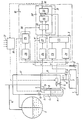
- This installation firstly comprises a pipe 1 in which the liquid to which one wishes to mix another liquid contained in a storage tank 2 circulates.
- the liquid circulating in circuit 1 is for example petrol and the additive of tetraethyl lead.
- An ejector 3 is mounted in a known manner on the pipe 1 to ensure mixing.
- the flow meter comprises a tank 4 which is in this case substantially cylindrical with a cover 5 at its upper part.
- the cover 5 is crossed on the one hand by a supply duct 6 coming from the storage tank 2 and on the other hand by a vent pipe 7.
- a plunger 8 is arranged in a known manner in the tank 4 to transmit the Archimedes thrust which is exerted on it to a force sensor 9, for example with extensometric gauge.
- a supply valve 10 is arranged on the supply duct 6 between the storage tank 2 and the tank 4.
- a drain pipe 11 is also connected to the bottom of the tank 4 between this tank and the ejector 3.
- a flow control valve 12 On the circuit 11 are successively arranged starting from the tank 4 a flow control valve 12, a safety valve 13 and a differential pressure sensor or vacuum transmitter 14 which is also connected to the open air by a pipe 15.
- the storage tank 2 is also vented at 16 while a conduit 17 connects the drain conduit 11 between the adjustment valve 12 and the safety valve 13 at the top of the supply conduit 6.
- the flow meter is primed by closing the regulating valve 12 and by opening the safety valve 13.
- the vacuum caused in the ejector 3 by the flow of the fluid in the duct 1 is transmitted by the pipe 17 to the tank 2 and causes priming.
- the flowmeter also includes an electronic assembly 18 which will be described in detail below.
- the regulating valve 12 is regulated by a flow regulating member 19 which may for example be a computer, one input of which is constituted by the output 20 of the flow meter, the other inputs 21 depending on other parameters of the system such as for example the flow in the pipeline.
- a flow regulating member 19 which may for example be a computer, one input of which is constituted by the output 20 of the flow meter, the other inputs 21 depending on other parameters of the system such as for example the flow in the pipeline.
- the computer 19 imposes the excitation current of the control valve 12 which current also constitutes an input i of the assembly 18.
- the installation finally includes a temperature transmitter sensor 22 which measures the temperature of the liquid circulating in the pipeline.
- the output of the sensor 22 corresponds to the input T of the assembly 18.
- the other inputs to the electronic assembly 18 are the input F connected to the force sensor 9 and the input P connected to the vacuum transmitter 14.
- the first processing unit I receives at P the output of the vacuum transmitter 14 on a square root extractor 23 and at i the excitation current of the regulation valve 12 on a circuit 24.
- the circuit 24 represents the transfer function of the control valve so that its input being constituted by the supply current of this valve, its output represents the passage section of the valve.
- the outputs of the square root extractor 23 and of the circuit 24 representing the transfer function of the control valve 12 are applied to an analog multiplier 25 whose AC output also constitutes the output of the first processing unit I.
- the processing unit 1 produces the product of the square root of the pressure downstream of the regulating valve 12 through the opening section of this valve so that its output is approximately proportional to the volume flow rate in the pipe 11 regardless of the opening or closing state of the supply valve 10.
- the second processing unit It firstly comprises a filter 26 into which the signal from the force sensor 9 is introduced in order to eliminate the background noise as well as the parasites due for example to vibrations.
- the output of the filter 26 is introduced into a digital differentiator 27, the output of which constitutes the output of the processing unit II.
- the output of the force sensor 9 representing the Archimedes thrust exerted by the liquid in the tank 4 on the plunger 8 is proportional to the quantity of fluid in the tank 4. Consequently when the supply valve 10 is closed and the liquid in the tank 4 flows in the conduit 11 the output of the digital differentiator 27 represents the flow in the conduit 11.
- the outputs of the two processing units 1 and II are applied to the calibration unit III which will be described in more detail below.
- the control circuit IV comprises on the one hand a level comparator 28 and on the other hand a sequence logic circuit 29 which receives the output of the comparator 28.
- the output of the force sensor 9 is applied to the input of the comparator 28 which compares this output with a first value corresponding to the minimum level of liquid in the tank 4 and to a second value corresponding to the maximum level.
- the logic gates 30 receive and transmit on the one hand the signal coming from the second processing unit II and on the other hand the output 20 of the flow meter by means of a feedback loop 31.
- the two outputs of the doors 30 are applied to the respectively positive and negative inputs of a digital comparator with memory 32.
- the comparator 32 therefore receives pulses on its two inputs when the doors 30 are open.
- the pulses received on the positive input have a frequency proportional to the flow rate measured by the force sensor 9 via the processing chain II and the pulses received on the negative input have a frequency proportional to the flow rate indicated by the flow meter . It can therefore be seen that when the doors 30 are open, the output of the flowmeter is controlled by the value measured by the force sensor 9.
- the CN output of comparator 32 is a binary number which when the doors 30 are open is proportional to the difference between the two inputs and which when the doors 30 close retains the same value as it had immediately before the doors closed 30.
- This output of comparator 32 is applied to an input of a programmable oscillator 33 and the other input receives the output of the first processing chain 1, that is to say the output of the multiplier 27.
- the programmable oscillator 33 delivers at its output, which is the output 20 of the flow meter, pulses whose frequency is proportional to the product CNxCA.
- control unit IV closes the logic doors 30 so that the output 20 of the flow meter follows the output of the pressure sensor 14 via the first processing unit 1 as described above.
- the programmable oscillator 33 then tracks the value of its AC input and consequently varies as a function of the flow rate as determined by the current i and the differential pressure measured by the vacuum transmitter 14.
- the output of the programmable oscillator 33 will vary like its AC input.
- the gates 30 will reconnect the CN input of the oscillator 33 the latter will then start to follow this CN input but the latter will also have been modified as a result of the variation of the flow.
- the memory comparator can take into account an average of the last output values of the second measurement chain and not the last value only.
Claims (15)
Priority Applications (1)
| Application Number | Priority Date | Filing Date | Title |
|---|---|---|---|
| AT83400214T ATE19550T1 (de) | 1982-02-03 | 1983-02-01 | Durchflussmesser und vorrichtung zum mischen eines zuschlagstoffes in eine fluessigkeit mit einem derartigen durchflussmesser. |
Applications Claiming Priority (2)
| Application Number | Priority Date | Filing Date | Title |
|---|---|---|---|
| FR8201708A FR2520864B1 (fr) | 1982-02-03 | 1982-02-03 | Debitmetre et installation de melange d'un additif dans un liquide comprenant un tel debitmetre |
| FR8201708 | 1982-02-03 |
Publications (2)
| Publication Number | Publication Date |
|---|---|
| EP0086145A1 EP0086145A1 (de) | 1983-08-17 |
| EP0086145B1 true EP0086145B1 (de) | 1986-04-30 |
Family
ID=9270618
Family Applications (1)
| Application Number | Title | Priority Date | Filing Date |
|---|---|---|---|
| EP83400214A Expired EP0086145B1 (de) | 1982-02-03 | 1983-02-01 | Durchflussmesser und Vorrichtung zum Mischen eines Zuschlagstoffes in eine Flüssigkeit mit einem derartigen Durchflussmesser |
Country Status (7)
| Country | Link |
|---|---|
| US (1) | US4522059A (de) |
| EP (1) | EP0086145B1 (de) |
| JP (1) | JPS58197521A (de) |
| AT (1) | ATE19550T1 (de) |
| DE (1) | DE3363227D1 (de) |
| FR (1) | FR2520864B1 (de) |
| OA (1) | OA07314A (de) |
Families Citing this family (11)
| Publication number | Priority date | Publication date | Assignee | Title |
|---|---|---|---|---|
| GB2190500A (en) * | 1986-05-03 | 1987-11-18 | Stc Plc | Liquid level sensor |
| US5263608A (en) * | 1991-06-04 | 1993-11-23 | Philip Morris Incorporated | Method and apparatus for dispensing a constant controlled volume of adhesive |
| US5313842A (en) * | 1992-01-02 | 1994-05-24 | Marsh-Mcbirnes, Inc. | Pump station flowmeter with sudden high inflow change detector |
| US5475614A (en) * | 1994-01-13 | 1995-12-12 | Micro-Trak Systems, Inc. | Method and apparatus for controlling a variable fluid delivery system |
| GB2286048B (en) * | 1994-01-26 | 1997-11-26 | Spirax Sarco Ltd | Flow meters |
| DE69420262T2 (de) * | 1994-02-08 | 2000-03-16 | Nippon Steel Corp | Metallischer wabenkörper für katalysator für autos und methode zu dessen herstellung |
| US5556009A (en) * | 1994-07-18 | 1996-09-17 | Wagner Spray Tech Corporation | Adjustable constant pressure caulk gun |
| DE19840989A1 (de) * | 1997-09-09 | 1999-03-18 | Tokyo Electron Ltd | Reinigungsverfahren und Reinigungsgerät |
| US6349852B1 (en) | 1999-05-04 | 2002-02-26 | Bunn-O-Matic Corporation | Cold beverage refill system |
| US6434772B1 (en) * | 2000-10-24 | 2002-08-20 | U.N.X. Incorporated | Chemical dispensing system |
| CN113137994B (zh) * | 2020-12-02 | 2022-03-11 | 中国原子能科学研究院 | 一种在线测量过滤131i气体体积的方法 |
Family Cites Families (8)
| Publication number | Priority date | Publication date | Assignee | Title |
|---|---|---|---|---|
| US2853877A (en) * | 1955-06-23 | 1958-09-30 | Oil Metering And Proc Equipmen | Rigid buoyancy mass liquid meter |
| FR1398916A (fr) * | 1964-04-02 | 1965-05-14 | Rochar Electronique | Banc d'étalonnage des mesureurs débitmétriques |
| US3550426A (en) * | 1969-03-18 | 1970-12-29 | Rotron Inc | Fluid meter field checking method and apparatus |
| GB1402876A (en) * | 1972-07-12 | 1975-08-13 | Lubrizol Corp | Liquid meter |
| IT1015999B (it) * | 1974-05-14 | 1977-05-20 | Isam Spa | Dispositivo per la misura pondera le di erogazione di liquidi |
| FR2448130A1 (fr) * | 1979-02-05 | 1980-08-29 | Octel Sa | Procede et dispositif de controle d'un debit de liquide |
| FR2448129A1 (fr) * | 1979-02-05 | 1980-08-29 | Octel Sa | Procede et dispositif de mesure d'un debit de liquide et application au controle d'un melange de liquide |
| FR2466003A1 (fr) * | 1979-09-24 | 1981-03-27 | Penet Pierre | Banc d'etalonnage de debitmetres et compteurs de liquide |
-
1982
- 1982-02-03 FR FR8201708A patent/FR2520864B1/fr not_active Expired
-
1983
- 1983-02-01 AT AT83400214T patent/ATE19550T1/de not_active IP Right Cessation
- 1983-02-01 EP EP83400214A patent/EP0086145B1/de not_active Expired
- 1983-02-01 DE DE8383400214T patent/DE3363227D1/de not_active Expired
- 1983-02-02 US US06/463,250 patent/US4522059A/en not_active Expired - Fee Related
- 1983-02-02 OA OA57908A patent/OA07314A/xx unknown
- 1983-02-03 JP JP58016850A patent/JPS58197521A/ja active Pending
Also Published As
| Publication number | Publication date |
|---|---|
| DE3363227D1 (en) | 1986-06-05 |
| US4522059A (en) | 1985-06-11 |
| JPS58197521A (ja) | 1983-11-17 |
| OA07314A (fr) | 1984-08-31 |
| FR2520864B1 (fr) | 1986-01-10 |
| ATE19550T1 (de) | 1986-05-15 |
| EP0086145A1 (de) | 1983-08-17 |
| FR2520864A1 (fr) | 1983-08-05 |
Similar Documents
| Publication | Publication Date | Title |
|---|---|---|
| EP0086145B1 (de) | Durchflussmesser und Vorrichtung zum Mischen eines Zuschlagstoffes in eine Flüssigkeit mit einem derartigen Durchflussmesser | |
| EP0524850B1 (de) | Verfahren zur gewichtsmässigen Dosierung beim Füllen von Behältern | |
| EP0406092B1 (de) | Vorrichtung zum Füllen von Behältern mit abgewogenen Mengen | |
| EP0243284B1 (de) | Künstliche Niere mit einer Anordnung zur Kontrolle der im Dialysatkreislauf fliessenden Flüssigkeitsmengen | |
| FR2628835A1 (de) | ||
| FR2520108A1 (fr) | Procede et installation de determination de valeurs dependant du debit massique d'une matiere a doser | |
| EP1196346A1 (de) | Verfahren zum befüllen eines behälters | |
| EP0418171B1 (de) | Kalibrierungsverfahren für einen Impulsantwort-Durchflussmesser | |
| EP1123251B1 (de) | Kontrollverfahren für das füllen von behältern mit einem fliessfähigen gut und einfüllvorrichtung zur durchführung dieses verfahrens | |
| EP0353197B1 (de) | Verfahren zur Gewichtsdosierung | |
| EP0473521B1 (de) | Verfahren und Vorrichtung zum Fördern von pulverförmigem oder körnigem Material in eine Stranggussform | |
| EP0881555A1 (de) | Methode zur Regelung des Wassersauerstoffgehaltes am Ausgang eines Gerätes zur Auflösung von Sauerstoff im Wasser und Vorrichtung zur Durchführung dieser Methode | |
| FR2958976A1 (fr) | Procede et dispositif d'elaboration d'un signal de consigne representatif d'un debit de carburant | |
| EP0401139B1 (de) | Gerät und Verfahren für die Ultrafilterungsmessung in einer Kunstniere | |
| EP0403401B2 (de) | Verfahren zur Kontrolle der Ultrafiltration und Vorrichtung zur Ausführung des Verfahrens | |
| FR2696644A1 (fr) | Dispositf d'échantillonnage de liquide de dialyse usagé. | |
| WO2022073612A1 (fr) | Dispositif de dosage pour une machine de fabrication de preparation liquide | |
| FR2499241A1 (fr) | Debitmetre | |
| FR2510750A1 (fr) | Procede et dispositif de controle et d'ajustement d'une quantite de liquide contenue dans un reservoir | |
| FR2597629A2 (fr) | Procede et dispositif d'automatisation d'un pressoir | |
| WO1987000636A1 (fr) | Procede et dispositif automatique de mesure de la teneur d'un composant soluble dans un produit pulverulent | |
| FR2822540A1 (fr) | Procede automatise de mesure de volume | |
| FR2794238A1 (fr) | Dispositif pour la mesure cyclique d'un debit | |
| CH717943A2 (fr) | Dispositif de dosage pour une machine de fabrication de préparation liquide. | |
| WO2023110173A1 (fr) | Dispositif de dosage pour une machine de fabrication de preparation liquide |
Legal Events
| Date | Code | Title | Description |
|---|---|---|---|
| PUAI | Public reference made under article 153(3) epc to a published international application that has entered the european phase |
Free format text: ORIGINAL CODE: 0009012 |
|
| AK | Designated contracting states |
Designated state(s): AT BE CH DE GB IT LI LU NL SE |
|
| 17P | Request for examination filed |
Effective date: 19831122 |
|
| GRAA | (expected) grant |
Free format text: ORIGINAL CODE: 0009210 |
|
| AK | Designated contracting states |
Kind code of ref document: B1 Designated state(s): AT BE CH DE GB IT LI LU NL SE |
|
| REF | Corresponds to: |
Ref document number: 19550 Country of ref document: AT Date of ref document: 19860515 Kind code of ref document: T |
|
| REF | Corresponds to: |
Ref document number: 3363227 Country of ref document: DE Date of ref document: 19860605 |
|
| ITF | It: translation for a ep patent filed |
Owner name: MODIANO & ASSOCIATI S.R.L. |
|
| PLBE | No opposition filed within time limit |
Free format text: ORIGINAL CODE: 0009261 |
|
| STAA | Information on the status of an ep patent application or granted ep patent |
Free format text: STATUS: NO OPPOSITION FILED WITHIN TIME LIMIT |
|
| 26N | No opposition filed | ||
| PGFP | Annual fee paid to national office [announced via postgrant information from national office to epo] |
Ref country code: SE Payment date: 19910103 Year of fee payment: 9 Ref country code: GB Payment date: 19910103 Year of fee payment: 9 |
|
| PGFP | Annual fee paid to national office [announced via postgrant information from national office to epo] |
Ref country code: BE Payment date: 19910115 Year of fee payment: 9 |
|
| PGFP | Annual fee paid to national office [announced via postgrant information from national office to epo] |
Ref country code: LU Payment date: 19910124 Year of fee payment: 9 Ref country code: AT Payment date: 19910124 Year of fee payment: 9 |
|
| ITTA | It: last paid annual fee | ||
| PGFP | Annual fee paid to national office [announced via postgrant information from national office to epo] |
Ref country code: NL Payment date: 19910228 Year of fee payment: 9 Ref country code: CH Payment date: 19910228 Year of fee payment: 9 |
|
| PGFP | Annual fee paid to national office [announced via postgrant information from national office to epo] |
Ref country code: DE Payment date: 19910325 Year of fee payment: 9 |
|
| EPTA | Lu: last paid annual fee | ||
| PG25 | Lapsed in a contracting state [announced via postgrant information from national office to epo] |
Ref country code: LU Free format text: LAPSE BECAUSE OF NON-PAYMENT OF DUE FEES Effective date: 19920201 Ref country code: GB Effective date: 19920201 Ref country code: AT Effective date: 19920201 |
|
| PG25 | Lapsed in a contracting state [announced via postgrant information from national office to epo] |
Ref country code: SE Effective date: 19920202 |
|
| PG25 | Lapsed in a contracting state [announced via postgrant information from national office to epo] |
Ref country code: BE Effective date: 19920228 |
|
| PG25 | Lapsed in a contracting state [announced via postgrant information from national office to epo] |
Ref country code: LI Effective date: 19920229 Ref country code: CH Effective date: 19920229 |
|
| BERE | Be: lapsed |
Owner name: OCTEL S.A. Effective date: 19920228 |
|
| PG25 | Lapsed in a contracting state [announced via postgrant information from national office to epo] |
Ref country code: NL Effective date: 19920901 |
|
| GBPC | Gb: european patent ceased through non-payment of renewal fee | ||
| NLV4 | Nl: lapsed or anulled due to non-payment of the annual fee | ||
| REG | Reference to a national code |
Ref country code: CH Ref legal event code: PL |
|
| PG25 | Lapsed in a contracting state [announced via postgrant information from national office to epo] |
Ref country code: DE Effective date: 19921103 |
|
| EUG | Se: european patent has lapsed |
Ref document number: 83400214.9 Effective date: 19920904 |