EP0086145B1 - Flow meter and device to mix in an additive with a fluid comprising such a flow meter - Google Patents
Flow meter and device to mix in an additive with a fluid comprising such a flow meter Download PDFInfo
- Publication number
- EP0086145B1 EP0086145B1 EP83400214A EP83400214A EP0086145B1 EP 0086145 B1 EP0086145 B1 EP 0086145B1 EP 83400214 A EP83400214 A EP 83400214A EP 83400214 A EP83400214 A EP 83400214A EP 0086145 B1 EP0086145 B1 EP 0086145B1
- Authority
- EP
- European Patent Office
- Prior art keywords
- flow meter
- container
- fact
- value
- tank
- Prior art date
- Legal status (The legal status is an assumption and is not a legal conclusion. Google has not performed a legal analysis and makes no representation as to the accuracy of the status listed.)
- Expired
Links
Images
Classifications
-
- G—PHYSICS
- G01—MEASURING; TESTING
- G01F—MEASURING VOLUME, VOLUME FLOW, MASS FLOW OR LIQUID LEVEL; METERING BY VOLUME
- G01F1/00—Measuring the volume flow or mass flow of fluid or fluent solid material wherein the fluid passes through a meter in a continuous flow
- G01F1/05—Measuring the volume flow or mass flow of fluid or fluent solid material wherein the fluid passes through a meter in a continuous flow by using mechanical effects
- G01F1/34—Measuring the volume flow or mass flow of fluid or fluent solid material wherein the fluid passes through a meter in a continuous flow by using mechanical effects by measuring pressure or differential pressure
- G01F1/36—Measuring the volume flow or mass flow of fluid or fluent solid material wherein the fluid passes through a meter in a continuous flow by using mechanical effects by measuring pressure or differential pressure the pressure or differential pressure being created by the use of flow constriction
- G01F1/363—Measuring the volume flow or mass flow of fluid or fluent solid material wherein the fluid passes through a meter in a continuous flow by using mechanical effects by measuring pressure or differential pressure the pressure or differential pressure being created by the use of flow constriction with electrical or electro-mechanical indication
-
- G—PHYSICS
- G01—MEASURING; TESTING
- G01F—MEASURING VOLUME, VOLUME FLOW, MASS FLOW OR LIQUID LEVEL; METERING BY VOLUME
- G01F15/00—Details of, or accessories for, apparatus of groups G01F1/00 - G01F13/00 insofar as such details or appliances are not adapted to particular types of such apparatus
- G01F15/02—Compensating or correcting for variations in pressure, density or temperature
-
- G—PHYSICS
- G01—MEASURING; TESTING
- G01F—MEASURING VOLUME, VOLUME FLOW, MASS FLOW OR LIQUID LEVEL; METERING BY VOLUME
- G01F25/00—Testing or calibration of apparatus for measuring volume, volume flow or liquid level or for metering by volume
- G01F25/10—Testing or calibration of apparatus for measuring volume, volume flow or liquid level or for metering by volume of flowmeters
- G01F25/17—Testing or calibration of apparatus for measuring volume, volume flow or liquid level or for metering by volume of flowmeters using calibrated reservoirs
-
- G—PHYSICS
- G01—MEASURING; TESTING
- G01F—MEASURING VOLUME, VOLUME FLOW, MASS FLOW OR LIQUID LEVEL; METERING BY VOLUME
- G01F3/00—Measuring the volume flow of fluids or fluent solid material wherein the fluid passes through the meter in successive and more or less isolated quantities, the meter being driven by the flow
- G01F3/36—Measuring the volume flow of fluids or fluent solid material wherein the fluid passes through the meter in successive and more or less isolated quantities, the meter being driven by the flow with stationary measuring chambers having constant volume during measurement
- G01F3/38—Measuring the volume flow of fluids or fluent solid material wherein the fluid passes through the meter in successive and more or less isolated quantities, the meter being driven by the flow with stationary measuring chambers having constant volume during measurement having only one measuring chamber
Definitions
- the present invention relates to a flow meter and to an installation for mixing a liquid additive in another liquid comprising such a flow meter.
- Flowmeters are already known comprising a tank disposed between a drain circuit in which it is desired to know the flow rate and a supply circuit from which the tank is filled when the level of the liquid that it contains drops below a value predetermined, and a plunger suspended in the tank via a force sensor.
- a drain circuit in which it is desired to know the flow rate and a supply circuit from which the tank is filled when the level of the liquid that it contains drops below a value predetermined
- the flow rate is determined by means of the force sensor. Indeed it measures the apparent weight of the diver, that is to say its weight less the buoyancy exerted by the liquid.
- the indication of the force sensor is therefore representative of the mass of liquid in the tank.
- the present invention aims to overcome the above drawbacks by providing a flow meter which has only one tank but which takes account of variations in flow during the emptying / filling phase of this tank.
- the subject of the invention is a flow meter of the type comprising a tank disposed between a permanently operating drain circuit in which it is desired to know the flow rate and a supply circuit from which the tank is filled when the liquid level that it contains drops below a predetermined value thereby obtaining emptying phases without filling the tank, called emptying phases, and emptying phases with filling of the tank, called emptying / filling phases, said flow meter further comprising a plunger suspended in the tank by means of a force sensor characterized in that it comprises, in combination, means independent of the tank and of the plunger capable of permanently supplying a signal approximately representative of the flow rate and calibration means capable of calibrating said means independent of the tank and the plunger from the indication given by the force sensor throughout the of said emptying phases.
- This flowmeter therefore comprises a first measurement chain which continuously provides an indication of the flow, whether the tank is in the emptying phase or in the emptying / filling phase.
- this measurement is calibrated by a second measurement chain at each emptying phase.
- the second measurement chain must on the other hand have at least the final precision sought since it is from these values that it provides during each emptying phase that the first measurement chain develops the measurement that it provides during the emptying phase / next filling.
- the output value of the flowmeter which is the subject of the present invention is continuous since it is the output value of the first calibrated measuring chain if one is in a phase of emptying the tank or not calibrated. if you are in an emptying / filling phase.
- the calibrated output value of the first measurement chain is in fact practically equal to the output value of the second measurement chain.
- the flow rate of the tank supply circuit as well as the volume of this tank are determined in a simple manner so that on the one hand the emptying phases are long enough for calibration to be carried out and that on the other apart from the emptying / filling phases are not too long since the output of the second measuring chain is then not calibrated.
- said means independent of the tank and the plunger comprise analog means whereas the calibration means comprise digital means.
- said means independent of the tank and of the plunger comprise a valve and a pressure sensor arranged in the circuit for emptying the tank.
- the first measurement chain of the flow meter according to the invention measures a volume flow whereas the second chain obviously measures a mass flow. This does not, moreover, have any drawback even if the flow rate that one wishes to measure is effectively the mass flow rate since the value indicated by the second measurement chain is recalibrated at each emptying phase.
- the density of the fluid whose flow rate is measured would have to vary significantly during an emptying / filling phase so that the measurement result is altered in terms of mass flow rate.
- the means independent of the tank and the plunger preferably include means for extracting the square root from the value supplied by the pressure sensor, means representative of the transfer function of the valve to deduce the cross section of its opening of its excitation current and means for multiplying said square root by the section of the valve opening.
- volume flow rate of a valve is directly proportional to the product of its opening section by the square root of the downstream-upstream differential pressure.
- This arrangement makes it possible in particular to take account of the variation in the supply pressure of the valve linked to the increase in level in the tank during the emptying / filling phase.
- the calibration means comprise means for deriving with respect to time the signal coming from the force sensor.
- the flow meter comprises means for interrupting the output of the bypass means during the emptying / filling phases of the tank.
- the calibration means then comprise a memory comparator able to compare the output value of the flow meter with the output value of the bypass means and to keep in memory the last output value of the bypass means when the output of the means of bypass is interrupted.
- this comparator keeps in memory the last output value of the first measurement chain so that no interruption is detected at the output of the flowmeter but that on the other hand the calibration is no longer carried out since the variation in the output value of the bypass means is no longer taken into account.
- the flowmeter also preferably comprises means capable of supplying a signal representative of the product of the signal supplied by said means independent of the tank and of the plunger by the output value of the memory comparator.
- the output of the flow meter which can correspond to the output of this multiplier, is during the emptying / filling phases directly proportional to the output value of the first measurement chain. Indeed, we have seen that during this phase the memory comparator only takes into account the last value taken by the output of the second chain of measurement during the previous emptying phase. On the other hand, during the emptying phases, this multiplier ensures the calibration of the first permanent measurement chain by the second standard measurement chain.
- the flow meter according to the invention can also comprise means able to compare the output value of the force sensor with a first value corresponding to the minimum level in the tank and with a second value corresponding to the maximum level in the tank.
- means may be provided to initiate a drain / fill phase when the output value of the force sensor reaches said first value and to end this phase when the output value of the force sensor reaches said second value.
- the invention also relates to an installation for mixing a liquid additive with another liquid, characterized in that it comprises a flow meter as described above in the circuit of said liquid additive.
- This installation can also include means for determining the excitation current of said valve arranged in the tank drain circuit as a function of the measured flow rate.
- These means may in particular include a dosing programmer which determines the set value of the excitation current of the valve and consequently of the flow rate as a function of the actual flow rate and possibly other parameters.
- the dosage should for example be 0.4 g per liter at 15 °. But this value varies with temperature.
- the invention in a particular embodiment therefore makes it possible to automatically adjust the flow rate of the additive as a function of the temperature of the liquid in which it is added.
- correction means are preferably arranged to modify the value supplied by the bypass means.
- bypass means consist of a digital bypass
- This installation firstly comprises a pipe 1 in which the liquid to which one wishes to mix another liquid contained in a storage tank 2 circulates.
- the liquid circulating in circuit 1 is for example petrol and the additive of tetraethyl lead.
- An ejector 3 is mounted in a known manner on the pipe 1 to ensure mixing.
- the flow meter comprises a tank 4 which is in this case substantially cylindrical with a cover 5 at its upper part.
- the cover 5 is crossed on the one hand by a supply duct 6 coming from the storage tank 2 and on the other hand by a vent pipe 7.
- a plunger 8 is arranged in a known manner in the tank 4 to transmit the Archimedes thrust which is exerted on it to a force sensor 9, for example with extensometric gauge.
- a supply valve 10 is arranged on the supply duct 6 between the storage tank 2 and the tank 4.
- a drain pipe 11 is also connected to the bottom of the tank 4 between this tank and the ejector 3.
- a flow control valve 12 On the circuit 11 are successively arranged starting from the tank 4 a flow control valve 12, a safety valve 13 and a differential pressure sensor or vacuum transmitter 14 which is also connected to the open air by a pipe 15.
- the storage tank 2 is also vented at 16 while a conduit 17 connects the drain conduit 11 between the adjustment valve 12 and the safety valve 13 at the top of the supply conduit 6.
- the flow meter is primed by closing the regulating valve 12 and by opening the safety valve 13.
- the vacuum caused in the ejector 3 by the flow of the fluid in the duct 1 is transmitted by the pipe 17 to the tank 2 and causes priming.
- the flowmeter also includes an electronic assembly 18 which will be described in detail below.
- the regulating valve 12 is regulated by a flow regulating member 19 which may for example be a computer, one input of which is constituted by the output 20 of the flow meter, the other inputs 21 depending on other parameters of the system such as for example the flow in the pipeline.
- a flow regulating member 19 which may for example be a computer, one input of which is constituted by the output 20 of the flow meter, the other inputs 21 depending on other parameters of the system such as for example the flow in the pipeline.
- the computer 19 imposes the excitation current of the control valve 12 which current also constitutes an input i of the assembly 18.
- the installation finally includes a temperature transmitter sensor 22 which measures the temperature of the liquid circulating in the pipeline.
- the output of the sensor 22 corresponds to the input T of the assembly 18.
- the other inputs to the electronic assembly 18 are the input F connected to the force sensor 9 and the input P connected to the vacuum transmitter 14.
- the first processing unit I receives at P the output of the vacuum transmitter 14 on a square root extractor 23 and at i the excitation current of the regulation valve 12 on a circuit 24.
- the circuit 24 represents the transfer function of the control valve so that its input being constituted by the supply current of this valve, its output represents the passage section of the valve.
- the outputs of the square root extractor 23 and of the circuit 24 representing the transfer function of the control valve 12 are applied to an analog multiplier 25 whose AC output also constitutes the output of the first processing unit I.
- the processing unit 1 produces the product of the square root of the pressure downstream of the regulating valve 12 through the opening section of this valve so that its output is approximately proportional to the volume flow rate in the pipe 11 regardless of the opening or closing state of the supply valve 10.
- the second processing unit It firstly comprises a filter 26 into which the signal from the force sensor 9 is introduced in order to eliminate the background noise as well as the parasites due for example to vibrations.
- the output of the filter 26 is introduced into a digital differentiator 27, the output of which constitutes the output of the processing unit II.
- the output of the force sensor 9 representing the Archimedes thrust exerted by the liquid in the tank 4 on the plunger 8 is proportional to the quantity of fluid in the tank 4. Consequently when the supply valve 10 is closed and the liquid in the tank 4 flows in the conduit 11 the output of the digital differentiator 27 represents the flow in the conduit 11.
- the outputs of the two processing units 1 and II are applied to the calibration unit III which will be described in more detail below.
- the control circuit IV comprises on the one hand a level comparator 28 and on the other hand a sequence logic circuit 29 which receives the output of the comparator 28.
- the output of the force sensor 9 is applied to the input of the comparator 28 which compares this output with a first value corresponding to the minimum level of liquid in the tank 4 and to a second value corresponding to the maximum level.
- the logic gates 30 receive and transmit on the one hand the signal coming from the second processing unit II and on the other hand the output 20 of the flow meter by means of a feedback loop 31.
- the two outputs of the doors 30 are applied to the respectively positive and negative inputs of a digital comparator with memory 32.
- the comparator 32 therefore receives pulses on its two inputs when the doors 30 are open.
- the pulses received on the positive input have a frequency proportional to the flow rate measured by the force sensor 9 via the processing chain II and the pulses received on the negative input have a frequency proportional to the flow rate indicated by the flow meter . It can therefore be seen that when the doors 30 are open, the output of the flowmeter is controlled by the value measured by the force sensor 9.
- the CN output of comparator 32 is a binary number which when the doors 30 are open is proportional to the difference between the two inputs and which when the doors 30 close retains the same value as it had immediately before the doors closed 30.
- This output of comparator 32 is applied to an input of a programmable oscillator 33 and the other input receives the output of the first processing chain 1, that is to say the output of the multiplier 27.
- the programmable oscillator 33 delivers at its output, which is the output 20 of the flow meter, pulses whose frequency is proportional to the product CNxCA.
- control unit IV closes the logic doors 30 so that the output 20 of the flow meter follows the output of the pressure sensor 14 via the first processing unit 1 as described above.
- the programmable oscillator 33 then tracks the value of its AC input and consequently varies as a function of the flow rate as determined by the current i and the differential pressure measured by the vacuum transmitter 14.
- the output of the programmable oscillator 33 will vary like its AC input.
- the gates 30 will reconnect the CN input of the oscillator 33 the latter will then start to follow this CN input but the latter will also have been modified as a result of the variation of the flow.
- the memory comparator can take into account an average of the last output values of the second measurement chain and not the last value only.
Abstract
Description
La présente invention concerne un débitmètre et une installation de mélange d'un additif liquide dans un autre liquide comprenant un tel débitmètre.The present invention relates to a flow meter and to an installation for mixing a liquid additive in another liquid comprising such a flow meter.
On connaît déjà des débitmètres comprenant une cuve disposée entre un circuit de vidange dans lequel on souhaite connaïtre le débit et un circuit d'alimentation à partir duquel la cuve est remplie lorsque le niveau du liquide qu'elle contient descend en dessous d'une valeur prédéterminée, et un plongeur suspendu dans la cuve par l'intermédiaire d'un capteur de force. (Voir document FR-A-2448129).Flowmeters are already known comprising a tank disposed between a drain circuit in which it is desired to know the flow rate and a supply circuit from which the tank is filled when the level of the liquid that it contains drops below a value predetermined, and a plunger suspended in the tank via a force sensor. (See document FR-A-2448129).
On connaît aussi des débitmètres du type ci-dessus dans lesquels la cuve est alternativement en phase de vidange sans remplissage (dite phase de vidange) et une phase de vidange avec remplissage (dite phase de vidange/remplissage). Pendant la phase de vidange le circuit d'alimentation est fermé et par conséquent le niveau dans la cuve baisse. Lorsque ce niveau a atteint la valeur prédéterminée le circuit d'alimentation est ouvert, le circuit de vidange restant bien entendu également ouvert. Le circuit d'alimentation est conçu de sorte que son débit soit très supérieur au débit du circuit de vidange de sorte que la durée de la phase vidange/remplissage soit relativement faible par rapport à la durée de la phase de vidange. Lorsque la niveau de liquide dans la cuve a atteint une nouvelle valeur supérieure prédéterminée le circuit d'alimentation est à nouveau fermé de sorte que le débitmètre se trouve de nouveau en phase de vidange.There are also known flowmeters of the above type in which the tank is alternately in the emptying phase without filling (called the emptying phase) and a draining phase with filling (called the emptying / filling phase). During the emptying phase the supply circuit is closed and consequently the level in the tank drops. When this level has reached the predetermined value, the supply circuit is open, the drain circuit, of course, also remaining open. The supply circuit is designed so that its flow rate is much higher than the flow rate of the drain circuit so that the duration of the drain / fill phase is relatively short compared to the duration of the drain phase. When the liquid level in the tank has reached a new predetermined higher value, the supply circuit is closed again so that the flow meter is again in the emptying phase.
Le détermination du débit est effectuée au moyen du capteur de force. En effet celui-ci mesure le poids apparent du plongeur c'est-à-dire son poids diminué de la poussée d'Archimède exercée par le liquide. L'indication du capteur de force est donc représentative de la masse de liquide dans la cuve.The flow rate is determined by means of the force sensor. Indeed it measures the apparent weight of the diver, that is to say its weight less the buoyancy exerted by the liquid. The indication of the force sensor is therefore representative of the mass of liquid in the tank.
Il suffit par conséquent de dériver cette indication pour connaître le débit massique. Un tel débitmètre comporte toutefois un inconvénient important qui réside dans le fait que le signal du capteur de force n'est plus significatif du débit pendant les phases de vidange/remplissage. Ceci est évident puisque la variation du niveau du liquide dans la cuve résulte alors de la différence entre le débit d'alimentation et de débit de vidange.It is therefore sufficient to derive this indication to know the mass flow rate. However, such a flow meter has an important drawback which resides in the fact that the signal from the force sensor is no longer significant of the flow during the emptying / filling phases. This is obvious since the variation in the level of the liquid in the tank then results from the difference between the feed rate and the drain rate.
On a déjà proposé pour remédier à cet inconvénient de considérer le débit pendant une phase de vidange/remplissage comme constant et égale à la dernière valeur qu'il avait pris pendant la phase de vidange immédiatement précédente.It has already been proposed to remedy this drawback of considering the flow rate during an emptying / filling phase as constant and equal to the last value it had taken during the immediately preceding emptying phase.
Cette solution n'est toutefois pas totalement satisfaisante dans la mesure où le débit pendant la phase de vidange/remplissage n'est connu que de façon approximative puisqu'on ne tient pas compte pendant cette phase de ses variations éventuelles dues à quelque cause que ce soit.This solution is however not entirely satisfactory insofar as the flow rate during the emptying / filling phase is only known approximately since it does not take account during this phase of its possible variations due to any cause whatsoever. is.
On a également proposé (Voir document FR-A-2448130) d'utiliser deux cuves de telle sorte que l'une soit toujours en phase de vidange pendant que l'autre est en phase de remplissage.It has also been proposed (see document FR-A-2448130) to use two tanks so that one is always in the emptying phase while the other is in the filling phase.
Cet agencement conduit toutefois à doubler de nombreux composants du débitmètre et à ajouter des vannes de commutation d'un circuit à l'autre, ce qui conduit à augmenter dans une proportion importante le coût du débitmètre ainsi que les risques de panne.However, this arrangement leads to doubling many components of the flow meter and adding switching valves from one circuit to another, which leads to a significant increase in the cost of the flow meter as well as the risk of failure.
Par ailleurs, le document FR-A-1398916 décrit un système d'étalonnage de débitmètre.Furthermore, the document FR-A-1398916 describes a flow meter calibration system.
La présente invention vise à pallier les inconvénients ci-dessus en fournissant un débitmètre qui ne comporte qu'une seule cuve mais qui tienne compte des variations de débit pendant la phase de vidange/remplissage de cette cuve.The present invention aims to overcome the above drawbacks by providing a flow meter which has only one tank but which takes account of variations in flow during the emptying / filling phase of this tank.
A cet effet l'invention a pour objet un débitmètre du type comprenant une cuve disposée entre un circuit de vidange fonctionnant en permanence dans lequel on souhaite connaître le débit et un circuit d'alimentation à partir duquel la cuve est remplie lorsque le niveau de liquide qu'elle contient descend en dessous d'une valeur prédéterminée en obtenant ainsi des phases de vidange sans remplissage de la cuve, dites phases de vidange, et des phases de vidange avec remplissage de la cuve, dites phases de vidange/remplissage, ledit débitmètre comprenant en outre un plongeur suspendu dans la cuve par l'intermédiaire d'un capteur de force caractérisé par le fait qu'il comporte en combinaison des moyens indépendants de la cuve et du plongeur aptes à fournir en permanence un signal représentatif approximativement du débit et des moyens d'étalonnage aptes à étalonner lesdits moyens indépendants de la cuve et du plongeur à partir de l'indication donnée par le capteur de force pendant toute la durée desdites phases de vidange.To this end, the subject of the invention is a flow meter of the type comprising a tank disposed between a permanently operating drain circuit in which it is desired to know the flow rate and a supply circuit from which the tank is filled when the liquid level that it contains drops below a predetermined value thereby obtaining emptying phases without filling the tank, called emptying phases, and emptying phases with filling of the tank, called emptying / filling phases, said flow meter further comprising a plunger suspended in the tank by means of a force sensor characterized in that it comprises, in combination, means independent of the tank and of the plunger capable of permanently supplying a signal approximately representative of the flow rate and calibration means capable of calibrating said means independent of the tank and the plunger from the indication given by the force sensor throughout the of said emptying phases.
Ce débitmètre comporte par conséquent une première chaîne de mesure qui fournit en permanence une indication du débit, que la cuve soit en phase de vidange ou en phase de vidange/remplissage.This flowmeter therefore comprises a first measurement chain which continuously provides an indication of the flow, whether the tank is in the emptying phase or in the emptying / filling phase.
L'imprécision de la mesure ainsi obtenue n'a pas d'incidence sur le résultat final.The imprecision of the measurement thus obtained does not affect the final result.
. En effet cette mesure est étalonnée par une deuxième chaîne de mesure à chaque phase de vidange. . Indeed, this measurement is calibrated by a second measurement chain at each emptying phase.
La deuxième chaîne de mesure doit par contre avoir au moins la précision finale recherchée puisque c'est à partir ces valeurs qu'elle fournit pendant chaque phase de vidange que la première chaîne de mesure élabore la mesure qu'elle fournit pendant la phase de vidange/remplissage suivante.The second measurement chain must on the other hand have at least the final precision sought since it is from these values that it provides during each emptying phase that the first measurement chain develops the measurement that it provides during the emptying phase / next filling.
On notera qu'il ne s'agit pas dans la présente invention de commuter simplement le débitmètre d'un chaîne de mesure indépendante de la cuve et du plongeur à une chaîne de mesure qui en dépend selon que l'on se trouve en phase de vidange/remplissage ou en phase de vidange.It will be noted that, in the present invention, it is not simply a question of switching the flowmeter from a measurement chain independent of the tank and of the plunger to a measurement chain which depends on it depending on whether one is in the phase of emptying / filling or in the emptying phase.
En effet un tel agencement conduirait à de brusques sauts de la valeur indiquée par le débitmètre un peu comme cela peut se produire dans les débitmètres à deux cuves.Indeed, such an arrangement would lead to sudden jumps in the value indicated by the flow meter much like it can happen in two tank flow meters.
Au contraire la valeur de sortie du débitmètre objet de la présente invention est continue puisqu'il s'agit de la valeur de sortie de la première chaîne de mesure étalonnée si l'on se trouve dans une phase de vidange de la cuve ou non étalonnée si l'on se trouve dans une phase de vidange/remplissage.On the contrary, the output value of the flowmeter which is the subject of the present invention is continuous since it is the output value of the first calibrated measuring chain if one is in a phase of emptying the tank or not calibrated. if you are in an emptying / filling phase.
On peut d'ailleurs faire en sorte comme on le verra ci-après que la valeur de sortie étalonnée de la première chaîne de mesure soit en fait pratiquement égale à la valeur de sortie de la deuxième chaîne de mesure.It can also be arranged, as will be seen below, that the calibrated output value of the first measurement chain is in fact practically equal to the output value of the second measurement chain.
Le débit du circuit d'alimentation de la cuve ainsi que le volume de cette cuve sont déterminés de manière simple de telle sorte que d'une part les phases de vidange soient suffisamment longues pour que l'étalonnage puisse se faire et que d'autre part les phases de vidange/remplissage ne soient pas trop longues puisque la sortie de la deuxième chaîne de mesure n'est alors pas étalonnée.The flow rate of the tank supply circuit as well as the volume of this tank are determined in a simple manner so that on the one hand the emptying phases are long enough for calibration to be carried out and that on the other apart from the emptying / filling phases are not too long since the output of the second measuring chain is then not calibrated.
Dans un mode de réalisation particulier lesdits moyens indépendants de la cuve et du plongeur comportent des moyens analogiques alors que les moyens d'étalonnage comportent des moyens numériques.In a particular embodiment, said means independent of the tank and the plunger comprise analog means whereas the calibration means comprise digital means.
Avantageusement lesdits moyens indépendants de la cuve et du plongeur comprennent une vanne et un capteur de pression disposés dans le circuit de vidange de la cuve.Advantageously, said means independent of the tank and of the plunger comprise a valve and a pressure sensor arranged in the circuit for emptying the tank.
On sait en effet que le débit dans une canalisation munie d'une vanne est fonction d'une part de l'ouverture de cette vanne et d'autre part de sa pression d'alimentation.It is known in fact that the flow rate in a pipe fitted with a valve depends on the one hand on the opening of this valve and on the other hand on its supply pressure.
On remarquera que dans ce cas la première chaîne de mesure du débitmètre selon l'invention mesure un débit volumique alors que la seconde chaîne mesure évidemment un débit massique. Ceci ne présente d'ailleurs pas d'inconvénient même si le débit que l'on souhaite mesurer est effectivement le débit massique puisque la valeur indiquée par la seconde chaîne de mesure est réétalonnée à chaque phase de vidange. Il faudrait que la densité du fluide dont on mesure le débit varie de façon significative pendant une phase de vidange/remplissage pour que le résultat de la mesure soit altéré en terme de débit massique.It will be noted that in this case the first measurement chain of the flow meter according to the invention measures a volume flow whereas the second chain obviously measures a mass flow. This does not, moreover, have any drawback even if the flow rate that one wishes to measure is effectively the mass flow rate since the value indicated by the second measurement chain is recalibrated at each emptying phase. The density of the fluid whose flow rate is measured would have to vary significantly during an emptying / filling phase so that the measurement result is altered in terms of mass flow rate.
Divers moyens peuvent être envisagés pour déduire le débit volumique des caractéristiques de la vanne et de la pression mais un agencement est particulièrement avantageux lorsque cette vanne est une vanne de régulation à commande électrique puisqu'alors son, courant d'alimentation est déterminé avec précision et que la section de son ouverture en dépend directement.Various means can be envisaged for deducing the volume flow rate from the characteristics of the valve and from the pressure, but an arrangement is particularly advantageous when this valve is an electrically controlled regulating valve since, at that time, its supply current is determined with precision and that the section of its opening depends directly on it.
Dans ce cas, les moyens indépendants de la cuve et du plongeur comportent de préférence des moyens pour extraire la racine carrée de la valeur fournie par le capteur de pression, des moyens représentatifs de la fonction de transfert de la vanne pour déduire la section de son ouverture de son courant d'excitation et des moyens pour multiplier ladite racine carrée par la section de l'ouverture de la vanne.In this case, the means independent of the tank and the plunger preferably include means for extracting the square root from the value supplied by the pressure sensor, means representative of the transfer function of the valve to deduce the cross section of its opening of its excitation current and means for multiplying said square root by the section of the valve opening.
On sait en effet que le débit volumique d'une vanne est directement proportionnel au produit de sa section d'ouverture par la racine carrée de la pression différentielle aval-amont.It is known in fact that the volume flow rate of a valve is directly proportional to the product of its opening section by the square root of the downstream-upstream differential pressure.
Cet agencement permet en particulier de tenir compte de la variation de la pression d'alimentation de la vanne liée à l'augmentation de niveau dans la cuve pendant la phase de vidange/remplissage.This arrangement makes it possible in particular to take account of the variation in the supply pressure of the valve linked to the increase in level in the tank during the emptying / filling phase.
De leur côté les moyens d'étalonnage comprennent des moyens pour dériver par rapport au temps le signal provenant du capteur de force.For their part, the calibration means comprise means for deriving with respect to time the signal coming from the force sensor.
Dans certains cas il pourra être utile de filtrer le signal provenant du capteur de force avant de le dériver. En effet, dans le cas contraire, des anomalies telles que des vibrations pourraient conduire à une interprétation erronnée du signal du capteur.In some cases it may be useful to filter the signal from the force sensor before deriving it. Otherwise, anomalies such as vibrations could lead to an erroneous interpretation of the sensor signal.
Dans un mode de réalisation particulier de l'invention le débitmètre comprend des moyens pour interrompre la sortie des moyens de dérivation pendant les phases de vidange/remplissage de la cuve.In a particular embodiment of the invention, the flow meter comprises means for interrupting the output of the bypass means during the emptying / filling phases of the tank.
On a vu en effet que le signal provenant de la deuxième chaîne de mesure n'est pas significatif pendant le remplissage de la cuve. On peut par conséquent interrompre la sortie des moyens de dérivation pendant cette phase.We have seen that the signal from the second measurement chain is not significant during the filling of the tank. It is therefore possible to interrupt the output of the bypass means during this phase.
Avantageusement les moyens d'étalonnage comprennent alors un comparateur à mémoire apte à comparer la valeur de sortie du débitmètre à la valeur de sortie des moyens de dérivation et à conserver en mémoire la dernière valeur de sortie des moyens de dérivation lorsque la sortie des moyens de dérivation est interrompue.Advantageously, the calibration means then comprise a memory comparator able to compare the output value of the flow meter with the output value of the bypass means and to keep in memory the last output value of the bypass means when the output of the means of bypass is interrupted.
Le rôle de ce comparateur est double.The role of this comparator is twofold.
Pendant la phase de vidange son rôle revient à comparer les valeurs de sortie des deux chaînes de mesure afin de réaliser l'étalonnage de la première chaîne de mesure par la deuxième chaîne de mesure.During the emptying phase, its role is to compare the output values of the two measuring chains in order to calibrate the first measuring chain by the second measuring chain.
Pendant la phase de vidange/remplissage ce comparateur garde en mémoire la dernière valeur de sortie de la première chaîne de mesure de sorte qu'aucune interruption n'est décelée à la sortie du débitmètre mais que par contre l'étalonnage n'est plus effectué puisqu'il n'est plus tenu compte de la variation de la valeur de sortie des moyens de dérivation.During the emptying / filling phase, this comparator keeps in memory the last output value of the first measurement chain so that no interruption is detected at the output of the flowmeter but that on the other hand the calibration is no longer carried out since the variation in the output value of the bypass means is no longer taken into account.
Le débitmètre comprend également de préférence des moyens aptes à fournir un signal représentatif du produit du signal fourni par lesdits moyens indépendants de la cuve et du plongeur par la valeur de sortie du comparateur à mémoire.The flowmeter also preferably comprises means capable of supplying a signal representative of the product of the signal supplied by said means independent of the tank and of the plunger by the output value of the memory comparator.
Ainsi la sortie du débitmètre, qui peut correspondre à la sortie de ce multiplicateur, est pendant les phases de vidange/remplissage directement proportionnelle à la valeur de sortie de la première chaîne de mesure. En effet on a vu que pendant cette phase le comparateur à mémoire ne prend en compte que la dernière valeur prise par la sortie de la deuxième chaîne de mesure lors de la phase de vidange précédente. Par contre pendant les phases de vidange ce multiplicateur permet d'assurer l'étalonnage de la première chaîne de mesure permanente par la deuxième chaîne de mesure étalon.Thus the output of the flow meter, which can correspond to the output of this multiplier, is during the emptying / filling phases directly proportional to the output value of the first measurement chain. Indeed, we have seen that during this phase the memory comparator only takes into account the last value taken by the output of the second chain of measurement during the previous emptying phase. On the other hand, during the emptying phases, this multiplier ensures the calibration of the first permanent measurement chain by the second standard measurement chain.
Le débitmètre selon l'invention peut également comprendre des moyens aptes à comparer la valeur de sortie du capteur de force avec une première valeur correspondant au niveau minimum dans la cuve et avec une deuxième valeur correspondant au niveau maximum dans la cuve.The flow meter according to the invention can also comprise means able to compare the output value of the force sensor with a first value corresponding to the minimum level in the tank and with a second value corresponding to the maximum level in the tank.
Dans ce cas das moyens peuvent être prévus pour déclencher une phase de vidange/remplissage lorsque la valeur de sortie du capteur de force atteint ladite première valeur et à mettre fin à cette phase lorsque la valeur de sortie du capteur de force atteint ladite deuxième valeur.In this case, means may be provided to initiate a drain / fill phase when the output value of the force sensor reaches said first value and to end this phase when the output value of the force sensor reaches said second value.
L'invention a également pour objet une installation de mélange d'un additif liquide dans un autre liquide, caractérisée par le fait qu'elle comprend un débitmètre tel que décrit ci-dessus dans le circuit dudit additif liquide.The invention also relates to an installation for mixing a liquid additive with another liquid, characterized in that it comprises a flow meter as described above in the circuit of said liquid additive.
Cette installation peut également comprendre des moyens pour déterminer le courant d'excitation de ladite vanne disposée dans le circuit de vidange de la cuve en fonction du débit mesuré.This installation can also include means for determining the excitation current of said valve arranged in the tank drain circuit as a function of the measured flow rate.
Ces moyens peuvent comprendre notamment un programmateur de dosage qui détermine la valeur de consigne du courant d'excitation de la vanne et par conséquent du débit en fonction du débit réel et éventuellement d'autres paramètres.These means may in particular include a dosing programmer which determines the set value of the excitation current of the valve and consequently of the flow rate as a function of the actual flow rate and possibly other parameters.
On peut également prévoir un capteur de température dudit autre liquide et des moyens pour corriger les moyens d'étalonnage en fonction de la température mesurée.It is also possible to provide a temperature sensor for said other liquid and means for correcting the calibration means as a function of the temperature measured.
Ceci est particulièrement intéressant lorsqu'on ne connaît que le débit volumique du liquide dans lequel on souhaite ajouter l'additif puisqu'il est alors nécessaire d'ajuster le débit massique de l'additif en fonction de la température.This is particularly advantageous when only the volume flow rate of the liquid is known in which it is desired to add the additive since it is then necessary to adjust the mass flow rate of the additive as a function of the temperature.
C'est ainsi que si l'on ajoute du plomb tétraéthyle à l'essence, le dosage doit être par exemple de 0,4 g par litre à 15°. Mais cette valeur varie avec la température.For example, if tetraethyl lead is added to petrol, the dosage should for example be 0.4 g per liter at 15 °. But this value varies with temperature.
L'invention dans un mode de réalisation particulier permet par conséquent d'ajuster auto- matiquemenf le débit de l'additif en fonction de la température du liquide dans lequel il est ajouté.The invention in a particular embodiment therefore makes it possible to automatically adjust the flow rate of the additive as a function of the temperature of the liquid in which it is added.
Ces moyens de correction sont de préférence agencés pour modifier la valeur fournie par les moyens de dérivation.These correction means are preferably arranged to modify the value supplied by the bypass means.
Dans le cas particulier où ces moyens de dérivation sont constitués par un dérivateur numérique cela revient à modifier la quantité d'additif correspondant à une impulsion à la sortie de ce dérivateur.In the particular case where these bypass means consist of a digital bypass, this amounts to modifying the quantity of additive corresponding to a pulse at the output of this bypass.
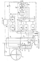
On décrira maintenant à titre d'exemple non limitatif un mode de réalisation particulier de l'invention en référence au dessin schématique annexé qui représente une installation de mélange et de dosage comprenant un débitmètre selon l'invention.A particular embodiment of the invention will now be described by way of nonlimiting example with reference to the appended schematic drawing which represents a mixing and dosing installation comprising a flow meter according to the invention.
Cette installation comporte tout d'abord une canalisation 1 dans laquelle circule le liquide auquel on souhaite mélanger un autre liquide contenu dans un réservoir de stockage 2.This installation firstly comprises a pipe 1 in which the liquid to which one wishes to mix another liquid contained in a
Le liquide circulant dans le circuit 1 est par exemple de l'essence et l'additif du plomb tétraéthyle.The liquid circulating in circuit 1 is for example petrol and the additive of tetraethyl lead.
Un éjecteur 3 est monté de façon connue sur la canalisation 1 pour assurer le mélange.An
Le débitmètre comprend une cuve 4 qui est dans le cas présent sensiblement cylindrique avec un couvercle 5 à sa partie supérieure.The flow meter comprises a tank 4 which is in this case substantially cylindrical with a cover 5 at its upper part.
Le couvercle 5 est traversé d'une part par un conduit d'alimentation 6 provenant du réservoir de stockage 2 et d'autre part par un conduit de mise à l'air libre 7.The cover 5 is crossed on the one hand by a supply duct 6 coming from the
Un plongeur 8 est disposé de façon connue dans la cuve 4 pour transmettre la poussée d'Archimède qui s'exerce sur lui à un capteur de force 9 par exemple à jauge extensométrique.A plunger 8 is arranged in a known manner in the tank 4 to transmit the Archimedes thrust which is exerted on it to a force sensor 9, for example with extensometric gauge.
Une vanne d'alimentation 10 est disposée sur le conduit d'alimentation 6 entre le réservoir de stockage 2 et la cuve 4.A supply valve 10 is arranged on the supply duct 6 between the
Un conduit de vidange 11 est par ailleurs raccordé au fond de la cuve 4 entre cette cuve et l'éjecteur 3.A
Sur le circuit 11 sont disposés successivement en partant de la cuve 4 une vanne de régulation de débit 12, une vanne de sécurité 13 et un capteur de pression différentiel ou transmetteur de vide 14 qui est par ailleurs relié à l'air libre par une canalisation 15.On the
Le réservoir de stockage 2 est également mis à l'air libre en 16 tandis qu'un conduit 17 relie le conduit de vidange 11 entre la vanne de réglage 12 et la vanne de sécurité 13 à la partie supérieure du conduit d'alimentation 6.The
L'amorçage du débitmètre s'effectue en fermant la vanne de régulation 12 et en ouvrant la vanne de sécurité 13. La dépression provoquée dans l'éjecteur 3 par l'écoulement du fluide dans le conduit 1 est transmise par la canalisation 17 au réservoir 2 et provoque l'amorçage.The flow meter is primed by closing the regulating
Le débitmètre comporte également un ensemble électronique 18 qui sera décrit en détail ci-après.The flowmeter also includes an
La vanne de régulation 12 est règlée par un organe de règlage de débit 19 qui peut être par exemple un calculateur dont une entrée est constituée par la sortie 20 du débitmètre, les autres entrées 21 dépendant d'autres paramètres du système tels par exemple le débit dans la canalisation.The regulating
Dans le cas présent le calculateur 19 impose le courant d'excitation de la vanne de règlage 12 lequel courant constitue également une entrée i de l'ensemble 18.In the present case, the
L'installation comporte enfin un capteur transmetteur de température 22 qui mesure la température du liquide circulant dans la canalisation.The installation finally includes a
La sortie du capteur 22 correspond à l'entrée T de l'ensemble 18.The output of the
Les autres entrées dans l'ensemble électronique 18 sont l'entrée F reliée au capteur de force 9 et l'entrée P reliée au transmetteur de vide 14.The other inputs to the
L'ensemble électronique 18 comprend d'une manière générale:
- une première unité de traitement 1 constituant avec le transmetteur de vide 14 et le circuit d'excitation de la vanne de réglage 12 une première chaîne de mesure,
- une deuxième unité de traitement Il constituant avec le capteur de force 9 une deuxième chaîne de mesure,
- une unité d'étalonnage III, et
- une unité de commande IV.
- a first processing unit 1 constituting, with the vacuum transmitter 14 and the excitation circuit of the
control valve 12, a first measuring chain, - a second processing unit II constituting with the force sensor 9 a second measurement chain,
- a calibration unit III, and
- a control unit IV.
La première unité de traitement I reçoit en P la sortie du transmetteur de vide 14 sur un extracteur de racine carrée 23 et en i le courant d'excitation de la vanne de régulation 12 sur un circuit 24.The first processing unit I receives at P the output of the vacuum transmitter 14 on a
Le circuit 24 représente la fonction de transfert de la vanne de régulation de sorte que son entrée étant constituée par le courant d'alimentation de cette vanne, sa sortie représente la section de passage de la vanne.The
Les sorties de l'extracteur de racines carrées 23 et du circuit 24 représentant la fonction de transfert de la vanne de régulation 12 sont appliquées à un multiplicateur analogique 25 dont la sortie CA constitue également la sortie de la première unité de traitement I.The outputs of the
On constate par conséquent que l'unité de traitement 1 réalise le produit de la racine carrée de la pression en aval de la vanne de régulation 12 par la section d'ouverture de cette vanne de sorte que sa sortie est approximativement proportionnelle au débit volumique dans la canalisation 11 quel que soit l'état d'ouverture ou de fermeture de la vanne d'alimentation 10.It can therefore be seen that the processing unit 1 produces the product of the square root of the pressure downstream of the regulating
La deuxième unité de traitement Il comporte tout d'abord un filtre 26 dans lequel est introduit le signal provenant du capteur de force 9 afin d'en éliminer le bruit de fond ainsi que les parasites dûs par exemple à des vibrations.The second processing unit It firstly comprises a
La sortie du filtre 26 est introduite dans un dérivateur numérique 27 dont la sortie constitue la sortie de l'unité de traitement II.The output of the
La sortie du capteur de force 9 représentant la poussée d'Archimède exercée par le liquide dans la cuve 4 sur le plongeur 8 est proportionnelle à la quantité de fluide dans la cuve 4. Par conséquent lorsque la vanne d'alimentation 10 est fermée et que le liquide de la cuve 4 s'écoule dans le conduit 11 la sortie du dérivateur numérique 27 représente le débit dans le conduit 11.The output of the force sensor 9 representing the Archimedes thrust exerted by the liquid in the tank 4 on the plunger 8 is proportional to the quantity of fluid in the tank 4. Consequently when the supply valve 10 is closed and the liquid in the tank 4 flows in the
Les sorties des deux unités de traitement 1 et Il sont appliquées à l'unité d'étalonnage III qui sera décrite plus en détail ci-après.The outputs of the two processing units 1 and II are applied to the calibration unit III which will be described in more detail below.
Le circuit de commande IV comporte d'une part un comparateur de niveau 28 et d'autre part un circuit logique de séquence 29 qui reçoit la sortie du comparateur 28.The control circuit IV comprises on the one hand a
La sortie du capteur de force 9 est appliquée à l'entrée du comparateur 28 qui compare cette sortie avec une première valeur correspondant au niveau minimal de liquide dans la cuve 4 et à une seconde valeur correspondant au niveau maximal.The output of the force sensor 9 is applied to the input of the
Lorsque le niveau minimal est détecté par le comparateur 28 celui-ci amène le circuit logique de séquence 29 à provoquer l'ouverture de la vanne d'alimentation 10 et lorsque le niveau maximal est détecté par le comparateur 28 celui-ci amène le circuit logique de séquence 29 à provoquer la fermeture de la vanne d'alimentation 10.When the minimum level is detected by the
Une autre sortie du circuit logique de séquence est appliquée à un ensemble de portes 30 de l'unité d'étalonnage III que l'on décrira maintenant en détail.Another output of the sequence logic circuit is applied to a set of
Les portes logiques 30 reçoivent et transmettent d'une part le signal issu de la deuxième unité de traitement Il et d'autre part la sortie 20 du débitmètre par l'intermédiaire d'une boucle de contre-réaction 31.The
Les deux sorties des portes 30 sont appliquées aux entrées respectivement positive et négative d'un comparateur numérique à mémoire 32.The two outputs of the
Le comparateur 32 reçoit donc des impulsions sur ses deux entrées lorsque les portes 30 sont ouvertes.The
Les impulsions reçues sur l'entrée positive ont une fréquence proportionnelle au débit mesuré par le capteur de force 9 par l'intermédiaire de la chaîne de traitement Il et les impulsions reçues sur l'entrée négative ont une fréquence proportionnelle au débit indiqué par le débitmètre. On constate par conséquent que lorsque les portes 30 sont ouvertes la sortie du débitmètre est asservie à la valeur mesurée par le capteur de force 9.The pulses received on the positive input have a frequency proportional to the flow rate measured by the force sensor 9 via the processing chain II and the pulses received on the negative input have a frequency proportional to the flow rate indicated by the flow meter . It can therefore be seen that when the
La sortie CN du comparateur 32 est un nombre binaire qui lorsque les portes 30 sont ouvertes est proportionnel à la différence entre les deux entrées et qui lorsque les portes 30 se ferment conserve la même valeur que celle qu'il avait immédiatement avant la fermeture des portes 30.The CN output of
Cette sortie du comparateur 32 est appliquée à une entrée d'un oscillateur programmable 33 sont l'autre entrée reçoit la sortie de la première chaîné de traitement 1 c'est-à-dire la sortie du multiplicateur 27.This output of
L'oscillateur programmable 33 délivre à sa sortie, qui est la sortie 20 du débitmètre, des impulsions dont la fréquence est proportionnelle au produit CNxCA.The
Par conséquent, lorsque la cuve 4 est en phase de remplissage l'unité de commande IV ferme les portes logiques 30 de sorte que la sortie 20 du débitmètre suit la sortie du capteur de pression 14 par l'intermédiaire de la première unité de traitement 1 comme cela à été décrit ci-dessus.Consequently, when the tank 4 is in the filling phase the control unit IV closes the
Lorsque le liquide dans la cuve 4 arrive à son niveau bas celui-ci est détecté par le comparateur 28 de sorte que l'unité de commande IV ferme les portes 30 et que la sortie CN du comparateur 32 devient constante et égale à la dernière valeur qu'elle avait précédemment.When the liquid in the tank 4 reaches its low level, this is detected by the
L'oscillateur programmable 33 suit alors la valeur de son entrée CA et varie par conséquent en fonction du débit tel que déterminé par le courant i et la pression différentielle mesurée par le transmetteur de vide 14.The
Lorsque le liquide dans la cuve 4 arrive de nouveau à son niveau haut celui-ci est détecté par le comparateur 28 et l'unité de commande 4 ouvre de nouveau les portes 30.When the liquid in the tank 4 arrives from again at its high level, this is detected by the
On notera en particulier que la sortie 20 du débitmètre ne subit jamais de discontinuité.It will be noted in particular that the
Ceci est évident lors du passage d'une phase de vidange à une phase de vidange/remplissage puisque l'entrée CN de l'oscillateur programmable 33 est maintenue constante à la valeur qu'elle avait précédemment.This is evident during the transition from a draining phase to a draining / filling phase since the CN input of the
Si pendant une phase de vidange/remplissage le débit est modifié la sortie de l'oscillateur programmable 33 variera comme son entrée CA. Lorsque, à la fin de cette phase de vidange/remplissage, les portes 30 reconnecteront l'entrée CN de l'oscillateur 33 celui-ci se mettra alors à suivre cette entrée CN mais celle-ci aura également été modifiée en conséquence du fait de la variation du débit.If during a drain / fill phase the flow rate is modified, the output of the
Là encore on ne notera par conséquent aucune discontinuité.Again, therefore, no discontinuity will be noted.
En outre, le comparateur à mémoire peut prendre en compte une moyenne des dernières valeurs de sortie de la deuxième chaîne de mesure et non pas la dernière valeur uniquement.In addition, the memory comparator can take into account an average of the last output values of the second measurement chain and not the last value only.
Claims (15)
Priority Applications (1)
| Application Number | Priority Date | Filing Date | Title |
|---|---|---|---|
| AT83400214T ATE19550T1 (en) | 1982-02-03 | 1983-02-01 | FLOWMETER AND DEVICE FOR MIXING AN AGGREGATE INTO A LIQUID WITH SUCH FLOWMETER. |
Applications Claiming Priority (2)
| Application Number | Priority Date | Filing Date | Title |
|---|---|---|---|
| FR8201708A FR2520864B1 (en) | 1982-02-03 | 1982-02-03 | FLOWMETER AND INSTALLATION FOR MIXING AN ADDITIVE IN A LIQUID COMPRISING SUCH A FLOWMETER |
| FR8201708 | 1982-02-03 |
Publications (2)
| Publication Number | Publication Date |
|---|---|
| EP0086145A1 EP0086145A1 (en) | 1983-08-17 |
| EP0086145B1 true EP0086145B1 (en) | 1986-04-30 |
Family
ID=9270618
Family Applications (1)
| Application Number | Title | Priority Date | Filing Date |
|---|---|---|---|
| EP83400214A Expired EP0086145B1 (en) | 1982-02-03 | 1983-02-01 | Flow meter and device to mix in an additive with a fluid comprising such a flow meter |
Country Status (7)
| Country | Link |
|---|---|
| US (1) | US4522059A (en) |
| EP (1) | EP0086145B1 (en) |
| JP (1) | JPS58197521A (en) |
| AT (1) | ATE19550T1 (en) |
| DE (1) | DE3363227D1 (en) |
| FR (1) | FR2520864B1 (en) |
| OA (1) | OA07314A (en) |
Families Citing this family (11)
| Publication number | Priority date | Publication date | Assignee | Title |
|---|---|---|---|---|
| GB2190500A (en) * | 1986-05-03 | 1987-11-18 | Stc Plc | Liquid level sensor |
| US5263608A (en) * | 1991-06-04 | 1993-11-23 | Philip Morris Incorporated | Method and apparatus for dispensing a constant controlled volume of adhesive |
| US5313842A (en) * | 1992-01-02 | 1994-05-24 | Marsh-Mcbirnes, Inc. | Pump station flowmeter with sudden high inflow change detector |
| US5475614A (en) * | 1994-01-13 | 1995-12-12 | Micro-Trak Systems, Inc. | Method and apparatus for controlling a variable fluid delivery system |
| GB2286048B (en) * | 1994-01-26 | 1997-11-26 | Spirax Sarco Ltd | Flow meters |
| DE69420262T2 (en) * | 1994-02-08 | 2000-03-16 | Nippon Steel Corp | METAL HONEYCOMB FOR CATALYST FOR CARS AND METHOD FOR THE PRODUCTION THEREOF |
| US5556009A (en) * | 1994-07-18 | 1996-09-17 | Wagner Spray Tech Corporation | Adjustable constant pressure caulk gun |
| DE19840989A1 (en) * | 1997-09-09 | 1999-03-18 | Tokyo Electron Ltd | Object wet cleaning method for e.g. semiconductor wafer |
| US6349852B1 (en) | 1999-05-04 | 2002-02-26 | Bunn-O-Matic Corporation | Cold beverage refill system |
| US6434772B1 (en) * | 2000-10-24 | 2002-08-20 | U.N.X. Incorporated | Chemical dispensing system |
| CN113137994B (en) * | 2020-12-02 | 2022-03-11 | 中国原子能科学研究院 | Online measurement filters131Method of I gas volume |
Family Cites Families (8)
| Publication number | Priority date | Publication date | Assignee | Title |
|---|---|---|---|---|
| US2853877A (en) * | 1955-06-23 | 1958-09-30 | Oil Metering And Proc Equipmen | Rigid buoyancy mass liquid meter |
| FR1398916A (en) * | 1964-04-02 | 1965-05-14 | Rochar Electronique | Calibration bench for flow meters |
| US3550426A (en) * | 1969-03-18 | 1970-12-29 | Rotron Inc | Fluid meter field checking method and apparatus |
| GB1402876A (en) * | 1972-07-12 | 1975-08-13 | Lubrizol Corp | Liquid meter |
| IT1015999B (en) * | 1974-05-14 | 1977-05-20 | Isam Spa | DEVICE FOR THE WEIGHT MEASUREMENT OF LIQUID DISPENSING |
| FR2448130A1 (en) * | 1979-02-05 | 1980-08-29 | Octel Sa | METHOD AND DEVICE FOR CONTROLLING A FLOW OF LIQUID |
| FR2448129A1 (en) * | 1979-02-05 | 1980-08-29 | Octel Sa | Measurement procedure for mass flow of petrol additive - utilises electrical resistance strain gauges for measuring liquid in cylinder for calculator circuit |
| FR2466003A1 (en) * | 1979-09-24 | 1981-03-27 | Penet Pierre | Automatic test station for volumetric flowmeter - uses timing circuits to measure time for flow of measured volume |
-
1982
- 1982-02-03 FR FR8201708A patent/FR2520864B1/en not_active Expired
-
1983
- 1983-02-01 DE DE8383400214T patent/DE3363227D1/en not_active Expired
- 1983-02-01 AT AT83400214T patent/ATE19550T1/en not_active IP Right Cessation
- 1983-02-01 EP EP83400214A patent/EP0086145B1/en not_active Expired
- 1983-02-02 US US06/463,250 patent/US4522059A/en not_active Expired - Fee Related
- 1983-02-02 OA OA57908A patent/OA07314A/en unknown
- 1983-02-03 JP JP58016850A patent/JPS58197521A/en active Pending
Also Published As
| Publication number | Publication date |
|---|---|
| FR2520864B1 (en) | 1986-01-10 |
| EP0086145A1 (en) | 1983-08-17 |
| JPS58197521A (en) | 1983-11-17 |
| DE3363227D1 (en) | 1986-06-05 |
| US4522059A (en) | 1985-06-11 |
| FR2520864A1 (en) | 1983-08-05 |
| ATE19550T1 (en) | 1986-05-15 |
| OA07314A (en) | 1984-08-31 |
Similar Documents
| Publication | Publication Date | Title |
|---|---|---|
| EP0086145B1 (en) | Flow meter and device to mix in an additive with a fluid comprising such a flow meter | |
| EP0524850B1 (en) | Weight-responsive dosage method for filling containers | |
| EP0406092B1 (en) | Device for filling containers with weighted measures | |
| EP0243284B1 (en) | Artificial kidney with a device for controlling the volumes of fluids flowing trough the dialysate circuit | |
| FR2628835A1 (en) | ||
| FR2520108A1 (en) | METHOD AND INSTALLATION FOR DETERMINING VALUES DEPENDING ON THE MASS FLOW OF A DOSING MATERIAL | |
| EP1196346A1 (en) | Method for filling a container | |
| EP0418171B1 (en) | Calibration method for an impulse response flowmeter | |
| EP1123251B1 (en) | Method for controlling the filling of containers with a flowable product and filling installation implementing said method | |
| EP0353197B1 (en) | Weight proportioning process | |
| FR2764089A1 (en) | METHOD FOR CONTROLLING THE OXYGEN CONTENT OF WATER AT THE OUTPUT OF AN APPARATUS FOR DISSOLVING OXYGEN IN WATER AND APPARATUS FOR IMPLEMENTING THE PROCESS | |
| EP0473521A1 (en) | Method and device for feeding a powder or granular material into a continuous casting mold | |
| FR2958976A1 (en) | METHOD AND DEVICE FOR PRODUCING A REPRESENTATIVE FIXTURE SIGNAL OF A FUEL RATE | |
| EP0401139B1 (en) | Apparatus and method for the measurement of ultrafiltrate in an artificial kidney | |
| EP0403401B2 (en) | Method to control ultrafiltration and device for carrying out this method | |
| FR3025027A1 (en) | METHOD AND SYSTEM FOR CONTROLLING A DEVICE COMPRISING A CONTAINER PROVIDED FOR CONTAINING A GAS AND A LIQUID | |
| FR2696644A1 (en) | Sampling appts. for dialysis solution - uses temporary holding vessel for liquid from dialysis machine and pump to take sample for analysis | |
| WO2022073612A1 (en) | Metering device for a machine for producing a liquid preparation | |
| FR2510750A1 (en) | Fuel gauging system for vehicle fuel tank - uses volume of gas under pressure injected into tank to determn. fuel contents by measuring pressure difference | |
| FR2597629A2 (en) | Method and device for automating at press | |
| WO1987000636A1 (en) | Method and device for automatically measuring the content of a soluble component in a pulverulent product | |
| FR2822540A1 (en) | Automatic accurate measurement or titration of small volumes of liquid in which small volumes are repeatedly measured in a calibrated measurement volume | |
| FR2794238A1 (en) | Flowmeter for use with a dosing pump that draws fluid from a storage tank has an extra buffer tank with level sensors and an electric valve for closing off the storage tank so that flow rate is determined from the buffer tank flow | |
| CH717943A2 (en) | Dosing device for a liquid preparation manufacturing machine. | |
| WO2023110173A1 (en) | Metering device for a machine for producing a liquid preparation |
Legal Events
| Date | Code | Title | Description |
|---|---|---|---|
| PUAI | Public reference made under article 153(3) epc to a published international application that has entered the european phase |
Free format text: ORIGINAL CODE: 0009012 |
|
| AK | Designated contracting states |
Designated state(s): AT BE CH DE GB IT LI LU NL SE |
|
| 17P | Request for examination filed |
Effective date: 19831122 |
|
| GRAA | (expected) grant |
Free format text: ORIGINAL CODE: 0009210 |
|
| AK | Designated contracting states |
Kind code of ref document: B1 Designated state(s): AT BE CH DE GB IT LI LU NL SE |
|
| REF | Corresponds to: |
Ref document number: 19550 Country of ref document: AT Date of ref document: 19860515 Kind code of ref document: T |
|
| REF | Corresponds to: |
Ref document number: 3363227 Country of ref document: DE Date of ref document: 19860605 |
|
| ITF | It: translation for a ep patent filed |
Owner name: MODIANO & ASSOCIATI S.R.L. |
|
| PLBE | No opposition filed within time limit |
Free format text: ORIGINAL CODE: 0009261 |
|
| STAA | Information on the status of an ep patent application or granted ep patent |
Free format text: STATUS: NO OPPOSITION FILED WITHIN TIME LIMIT |
|
| 26N | No opposition filed | ||
| PGFP | Annual fee paid to national office [announced via postgrant information from national office to epo] |
Ref country code: SE Payment date: 19910103 Year of fee payment: 9 Ref country code: GB Payment date: 19910103 Year of fee payment: 9 |
|
| PGFP | Annual fee paid to national office [announced via postgrant information from national office to epo] |
Ref country code: BE Payment date: 19910115 Year of fee payment: 9 |
|
| PGFP | Annual fee paid to national office [announced via postgrant information from national office to epo] |
Ref country code: LU Payment date: 19910124 Year of fee payment: 9 Ref country code: AT Payment date: 19910124 Year of fee payment: 9 |
|
| ITTA | It: last paid annual fee | ||
| PGFP | Annual fee paid to national office [announced via postgrant information from national office to epo] |
Ref country code: NL Payment date: 19910228 Year of fee payment: 9 Ref country code: CH Payment date: 19910228 Year of fee payment: 9 |
|
| PGFP | Annual fee paid to national office [announced via postgrant information from national office to epo] |
Ref country code: DE Payment date: 19910325 Year of fee payment: 9 |
|
| EPTA | Lu: last paid annual fee | ||
| PG25 | Lapsed in a contracting state [announced via postgrant information from national office to epo] |
Ref country code: LU Free format text: LAPSE BECAUSE OF NON-PAYMENT OF DUE FEES Effective date: 19920201 Ref country code: GB Effective date: 19920201 Ref country code: AT Effective date: 19920201 |
|
| PG25 | Lapsed in a contracting state [announced via postgrant information from national office to epo] |
Ref country code: SE Effective date: 19920202 |
|
| PG25 | Lapsed in a contracting state [announced via postgrant information from national office to epo] |
Ref country code: BE Effective date: 19920228 |
|
| PG25 | Lapsed in a contracting state [announced via postgrant information from national office to epo] |
Ref country code: LI Effective date: 19920229 Ref country code: CH Effective date: 19920229 |
|
| BERE | Be: lapsed |
Owner name: OCTEL S.A. Effective date: 19920228 |
|
| PG25 | Lapsed in a contracting state [announced via postgrant information from national office to epo] |
Ref country code: NL Effective date: 19920901 |
|
| GBPC | Gb: european patent ceased through non-payment of renewal fee | ||
| NLV4 | Nl: lapsed or anulled due to non-payment of the annual fee | ||
| REG | Reference to a national code |
Ref country code: CH Ref legal event code: PL |
|
| PG25 | Lapsed in a contracting state [announced via postgrant information from national office to epo] |
Ref country code: DE Effective date: 19921103 |
|
| EUG | Se: european patent has lapsed |
Ref document number: 83400214.9 Effective date: 19920904 |