EP0085779A1 - Vorrichtung und Verfahren zum kontinuierlichen Kontaktieren einer flüssigen Phase mit einer festen Phase im Gegenstrom - Google Patents
Vorrichtung und Verfahren zum kontinuierlichen Kontaktieren einer flüssigen Phase mit einer festen Phase im Gegenstrom Download PDFInfo
- Publication number
- EP0085779A1 EP0085779A1 EP82111886A EP82111886A EP0085779A1 EP 0085779 A1 EP0085779 A1 EP 0085779A1 EP 82111886 A EP82111886 A EP 82111886A EP 82111886 A EP82111886 A EP 82111886A EP 0085779 A1 EP0085779 A1 EP 0085779A1
- Authority
- EP
- European Patent Office
- Prior art keywords
- column
- liquid phase
- solid
- solid phase
- phase
- Prior art date
- Legal status (The legal status is an assumption and is not a legal conclusion. Google has not performed a legal analysis and makes no representation as to the accuracy of the status listed.)
- Granted
Links
- 239000007787 solid Substances 0.000 title claims description 14
- 238000000034 method Methods 0.000 title claims description 8
- 239000007788 liquid Substances 0.000 title description 4
- 239000007791 liquid phase Substances 0.000 claims abstract description 29
- 239000007790 solid phase Substances 0.000 claims abstract description 24
- 241001503485 Mammuthus Species 0.000 claims description 11
- 239000012530 fluid Substances 0.000 claims 1
- OKTJSMMVPCPJKN-UHFFFAOYSA-N Carbon Chemical compound [C] OKTJSMMVPCPJKN-UHFFFAOYSA-N 0.000 description 23
- 239000002351 wastewater Substances 0.000 description 10
- 230000005484 gravity Effects 0.000 description 3
- 239000003245 coal Substances 0.000 description 2
- 238000000605 extraction Methods 0.000 description 2
- 239000000126 substance Substances 0.000 description 2
- 229910000831 Steel Inorganic materials 0.000 description 1
- 230000031018 biological processes and functions Effects 0.000 description 1
- 238000006243 chemical reaction Methods 0.000 description 1
- 238000004140 cleaning Methods 0.000 description 1
- 238000004939 coking Methods 0.000 description 1
- 238000002309 gasification Methods 0.000 description 1
- 239000010842 industrial wastewater Substances 0.000 description 1
- 239000004615 ingredient Substances 0.000 description 1
- 229910052751 metal Inorganic materials 0.000 description 1
- 239000002184 metal Substances 0.000 description 1
- 150000002739 metals Chemical class 0.000 description 1
- 239000000203 mixture Substances 0.000 description 1
- 239000003921 oil Substances 0.000 description 1
- 235000019198 oils Nutrition 0.000 description 1
- 239000002245 particle Substances 0.000 description 1
- 239000012071 phase Substances 0.000 description 1
- 238000002360 preparation method Methods 0.000 description 1
- 230000007420 reactivation Effects 0.000 description 1
- 230000008929 regeneration Effects 0.000 description 1
- 238000011069 regeneration method Methods 0.000 description 1
- 230000001105 regulatory effect Effects 0.000 description 1
- 239000011949 solid catalyst Substances 0.000 description 1
- 239000010959 steel Substances 0.000 description 1
- 235000015112 vegetable and seed oil Nutrition 0.000 description 1
- 239000008158 vegetable oil Substances 0.000 description 1
- XLYOFNOQVPJJNP-UHFFFAOYSA-N water Substances O XLYOFNOQVPJJNP-UHFFFAOYSA-N 0.000 description 1
Images
Classifications
-
- C—CHEMISTRY; METALLURGY
- C02—TREATMENT OF WATER, WASTE WATER, SEWAGE, OR SLUDGE
- C02F—TREATMENT OF WATER, WASTE WATER, SEWAGE, OR SLUDGE
- C02F1/00—Treatment of water, waste water, or sewage
- C02F1/28—Treatment of water, waste water, or sewage by sorption
- C02F1/283—Treatment of water, waste water, or sewage by sorption using coal, charred products, or inorganic mixtures containing them
-
- B—PERFORMING OPERATIONS; TRANSPORTING
- B01—PHYSICAL OR CHEMICAL PROCESSES OR APPARATUS IN GENERAL
- B01D—SEPARATION
- B01D11/00—Solvent extraction
- B01D11/02—Solvent extraction of solids
- B01D11/0207—Control systems
-
- B—PERFORMING OPERATIONS; TRANSPORTING
- B01—PHYSICAL OR CHEMICAL PROCESSES OR APPARATUS IN GENERAL
- B01D—SEPARATION
- B01D11/00—Solvent extraction
- B01D11/02—Solvent extraction of solids
- B01D11/0215—Solid material in other stationary receptacles
- B01D11/0223—Moving bed of solid material
-
- B—PERFORMING OPERATIONS; TRANSPORTING
- B01—PHYSICAL OR CHEMICAL PROCESSES OR APPARATUS IN GENERAL
- B01D—SEPARATION
- B01D24/00—Filters comprising loose filtering material, i.e. filtering material without any binder between the individual particles or fibres thereof
- B01D24/28—Filters comprising loose filtering material, i.e. filtering material without any binder between the individual particles or fibres thereof with the filter bed moving during the filtration
- B01D24/30—Translation
-
- B—PERFORMING OPERATIONS; TRANSPORTING
- B01—PHYSICAL OR CHEMICAL PROCESSES OR APPARATUS IN GENERAL
- B01D—SEPARATION
- B01D24/00—Filters comprising loose filtering material, i.e. filtering material without any binder between the individual particles or fibres thereof
- B01D24/38—Feed or discharge devices
- B01D24/386—Feed or discharge devices internal recirculation
-
- B—PERFORMING OPERATIONS; TRANSPORTING
- B01—PHYSICAL OR CHEMICAL PROCESSES OR APPARATUS IN GENERAL
- B01D—SEPARATION
- B01D24/00—Filters comprising loose filtering material, i.e. filtering material without any binder between the individual particles or fibres thereof
- B01D24/46—Regenerating the filtering material in the filter
- B01D24/4668—Regenerating the filtering material in the filter by moving the filtering element
- B01D24/4689—Displacement of the filtering material to a compartment of the filtering device for regeneration
-
- B—PERFORMING OPERATIONS; TRANSPORTING
- B01—PHYSICAL OR CHEMICAL PROCESSES OR APPARATUS IN GENERAL
- B01D—SEPARATION
- B01D24/00—Filters comprising loose filtering material, i.e. filtering material without any binder between the individual particles or fibres thereof
- B01D24/48—Filters comprising loose filtering material, i.e. filtering material without any binder between the individual particles or fibres thereof integrally combined with devices for controlling the filtration
- B01D24/4869—Filters comprising loose filtering material, i.e. filtering material without any binder between the individual particles or fibres thereof integrally combined with devices for controlling the filtration by level measuring
-
- B—PERFORMING OPERATIONS; TRANSPORTING
- B01—PHYSICAL OR CHEMICAL PROCESSES OR APPARATUS IN GENERAL
- B01J—CHEMICAL OR PHYSICAL PROCESSES, e.g. CATALYSIS OR COLLOID CHEMISTRY; THEIR RELEVANT APPARATUS
- B01J8/00—Chemical or physical processes in general, conducted in the presence of fluids and solid particles; Apparatus for such processes
- B01J8/18—Chemical or physical processes in general, conducted in the presence of fluids and solid particles; Apparatus for such processes with fluidised particles
- B01J8/20—Chemical or physical processes in general, conducted in the presence of fluids and solid particles; Apparatus for such processes with fluidised particles with liquid as a fluidising medium
-
- C—CHEMISTRY; METALLURGY
- C02—TREATMENT OF WATER, WASTE WATER, SEWAGE, OR SLUDGE
- C02F—TREATMENT OF WATER, WASTE WATER, SEWAGE, OR SLUDGE
- C02F1/00—Treatment of water, waste water, or sewage
- C02F1/28—Treatment of water, waste water, or sewage by sorption
-
- B—PERFORMING OPERATIONS; TRANSPORTING
- B01—PHYSICAL OR CHEMICAL PROCESSES OR APPARATUS IN GENERAL
- B01D—SEPARATION
- B01D11/00—Solvent extraction
- B01D2011/002—Counter-current extraction
Definitions
- This known method enables the removal of organic substances that are difficult to biodegrade or interfere with biological processes.
- Such wastewater can occur, for example, in coking plants, coal gasification plants, and plants in the oil, steel and chemical industries.
- this wastewater is cleaned in a special design, through which counter-current flow layer adsorber flows, the wastewater being led from bottom to top and the activated carbon from top to bottom.
- the activated carbon to be used is guided in this column-like device from top to bottom in counterflow to the waste water stream. At the point of entry of the wastewater, the activated carbon is led through a narrow point.
- the spent activated carbon is then led out of the waste water stream at the lower end of the column and fed continuously to the regeneration stage in a mixture with water by means of a pipe arranged axially to the column.
- the object of the invention is a device which provides a uniform current of the solid phase, e.g. granular activated carbon allows, and in the solid stream has little or no obstacles.
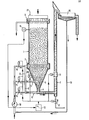
- the invention relates to a device for continuously contacting a liquid phase with a solid phase in countercurrent, which is characterized in that it consists of a column 1, the inflow ring arranged on the column 1 for the liquid phase 2, the conically arranged column base 3, the Discharge opening for the solid phase 4 on the column 1 below the inflow ring for the liquid phase 2, the line 5, which is arranged in the column bottom 3, the line 6, which is connected to the discharge opening for the solid phase 4 and the mammoth pump 7 and the overflow for the liquid phase 9, the lines 5 and 6 being connected via the line 8 to the inflow ring for the liquid phase 2.
- Another object of the invention is a process for the continuous contacting of a liquid phase with a solid phase in countercurrent by means of a column 1, which is characterized in that the discharge of the solid from the lower part of the column 1 by a slurrying device, represented by the - Lines 4,5 and 6, in cooperation with the mammoth pump 7.
- the solids can be discharged intermittently by simultaneously feeding the conveying liquid to the elutriation device and the conveying gas to the mammoth pump 7 in steps.
- the discharge of the solids can be controlled by means of the level controller 13, which gives a signal to the interval switch 12 when the solids level in the column 1 increases.
- one or more unbalance motors 20, which are arranged on the wall of the column 1 ′ and / or the column base 3, can be operated during the discharge period.
- the liquid phase for example industrial waste water, is introduced into the column 1 via the inflow ring 2. It flows in countercurrent to the solid phase to the upper end of the column 1 and is removed from the column 1 at the overflow for the liquid phase 9, in the example of the waste water in a purified form.
- the solid phase is guided at the lower end of the column 1 by means of the conically arranged column base 3 to the discharge opening for the solid phase 4.
- the conically arranged column base 3 or the wall of the column 1 can be shaken by means of one or more unbalance motors 20.
- the discharge opening 4 is connected to the line 6, which in turn is connected to the mammoth pump 7. At intervals, part of the liquid phase is introduced into the column via the line 5, which leads into the conically arranged column base 3.
- the supply of liquid phase to the inflow ring 2 can be interrupted in whole or in part, while at the same time part of the pulse flow of the liquid phase is also conducted via line 8 to line 6 of the mammoth pump.
- the solid phase is conveyed into the mammoth pump 7 after passing through the discharge opening 4 and with it to the separating device 10.
- the solid phase optionally after preparation, e.g. a reactivation of the activated carbon, can be abandoned at the upper end of column 1.
- the separated liquid phase can be fed via line 19 to the liquid phase circuit on the suction side of the pump 18.
- the liquid phase is supplied to the device according to the invention by the feed pump 18.
- the entry of the solid (activated carbon) into the column 1 takes place at the tip 21 of the column via a metering device, such as e.g. a belt scale or a dosing screw.
- the solids discharge from the conical column base 3 is brought about by the continuous operation of the mammoth pump 7 and the slurrying device (represented by lines 4, 5 and 6).
- the valves 11, 15, 10 and 17 are opened at the same time and the valve 14 is completely or partially closed.
- the valves 15 and 16 conveying liquid into the lower part of the column 1 - the column base 3 - and via the valve 17 conveying gas (eg air) into the mammoth pump 7.
- the actuation of the valves - which can be done electrically, pneumatically or hydraulically - is controlled by the interval switch 12.
- the solids flow is regulated by the level controller 13, which gives a signal to the interval switch 12 when the solids level rises.
- the device according to the invention has the advantage that there is no undesirable caking of the solid phase at the discharge opening of the column and thus clogging of the discharge opening.
- the solid phase can slide downwards evenly due to the force of gravity because there are no disturbing internals in the device.
Landscapes
- Chemical & Material Sciences (AREA)
- Chemical Kinetics & Catalysis (AREA)
- Engineering & Computer Science (AREA)
- Organic Chemistry (AREA)
- Life Sciences & Earth Sciences (AREA)
- Hydrology & Water Resources (AREA)
- Environmental & Geological Engineering (AREA)
- Water Supply & Treatment (AREA)
- Automation & Control Theory (AREA)
- Combustion & Propulsion (AREA)
- Devices And Processes Conducted In The Presence Of Fluids And Solid Particles (AREA)
- Extraction Or Liquid Replacement (AREA)
Abstract
Description
- Es ist bekannt, flüssige Phasen mit festen Phasen zu kontaktieren. So werden beispielsweise Abwässer, die mit organischen Inhaltsstoffen belastet sind, mittels körniger Aktivkohle gereinigt.
- Durch dieses bekannte Verfahren wird die Entfernung organischer Stoffe, die biologisch schwer abbaubar sind oder biologische Vorgänge stören, ermöglicht. Derartige Abwässer können beispielsweise bei Kokerei-, Kohlevergasungsanlagen, sowie Anlagen der Erdöl-, Stahl- und chemischen Industrie anfallen.
- Die Reinigung dieser Abwässer geschieht bekannterweise in einem im Gegenstrom durchströmten Wanderschichtadsorber spezieller Konstruktion, wobei das Abwasser von unten nach oben und die Aktivkohle von oben nach unten geführt wird.
- Andere bekannte Anwendungen des Kontaktierens einer flüssigen Phase mit einer festen Phase sind beispielsweise die Reinigung von organischen Lösungen, Reaktionen in Lösungen an festen Katalysatoren, die naBmetallurgische Gewinnung von Metallen, die Gewinnung pflanzlicher öle aus ölsaat o.ä.
- Aus der Zeitschrift Chem.Ind. XXVII/Juni 1975, Seiten 309 bis 311 ist eine Vorrichtung zum Kontaktieren von flüssigen mit festen Phasen bekannt, mittels welcher Abwässer an Aktivkohle aus Steinkohle regeneriert werden.
- Die zu verwendende Aktivkohle wird in dieser säulenartigen Vorrichtung von oben nach unten im Gegenstrom zu dem Abwasserstrom geführt. Am Ort des Eintritts des Abwassers wird dabei die Aktivkohle über eine Engstelle geführt.
- Die verbrauchte Aktivkohle wird anschliessend an dem unteren Ende der Säule aus dem Abwasserstrom geführt und mittels einer axial zu der Säule angeordneten Rohrleitung kontinuierlich im Gemisch mit Wasser der Regenerationsstufe zugeführt.
- Bei der Anwendung dieser Vorrichtung zur Reinigung von Abwässern unter Verwendung von körnigen Aktivkohlen, die eine breite TeilchengröBenverteilung aufweisen, ergeben sich nachteiligerweise unterwünschte Verstopfungen an der Austragsvorrichtung für die gebrauchte Aktivkohle.
- Aufgabe der Erfindung ist eine Vorrichtung, die einen gleichmässigen Strom der festen Phase, z.B. körniger Aktivkohle ermöglicht, sowie in dem Feststoffstrom wenig oder keine Hindernisse aufweist.
- Gegenstand der Erfindung ist eine Vorrichtung zum kontinuierlichen Kontaktieren einer flüssigen Phase mit einer festen Phase im Gegenstrom, welche dadurch gekennzeichnet ist, daß sie aus einer Säule 1, dem an der Säule 1 angeordneten Anströmring für die flüssige Phase 2 dem konisch angeordneten Säulenboden 3, der Austragsöffnung für die feste Phase 4 an der Säule 1 unterhalb des Anströmringes für die flüssige Phase 2, der Leitung 5, die in dem Säulenboden 3 angeordnet ist, der Leitung 6, die mit der Austragsöffnung für die feste Phase 4 und der Mammutpumpe 7 verbunden ist und dem überlauf für die flüssige Phase 9 besteht, wobei die Leitungen 5 und 6 über die Leitung 8 mit dem Anströmring für die flüssige Phase 2 verbunden sind.
- Ein weiterer Gegenstand der Erfindung ist ein Verfahren zum kontinuierlichen Kontaktieren einer flüssigen Phase mit einer festen Phase im Gegenstrom mittels einer Säule 1, welches dadurch gekennzeichnet ist, daß man den Austrag des Feststoffes aus dem unteren Teil der Säule 1 durch eine Ausschlämmvorrichtung, dargestellt durch die-Leitungen 4,5 und 6, im Zusammenwirken mit der Mammutpumpe 7 durchführt.
- Dabei kann man den Austrag des Feststoffes intermittierend durch gleichzeitige, stoßweise Aufgabe der Förderflüssigkeit zur Ausschlämmvorrichtung und des Fördergases zur Mammutpumpe 7 durchführen.
- Den Austrag des Feststoffes kann man mittels des Niveaureglers 13, der beim Anstieg des Feststoffniveaus in der Säule 1 ein Signal an den Intervallschalter 12 gibt, steuern.
- Zusätzlich kann man während der Austragperiode einen oder mehrere Unwuchtmotoren 20, die an der Wand der Säule 1' und/oder dem Säulenboden 3 angeordnet sind, betreiben.
- Die erfindungsgemäße Vorrichtung und das erfindungsgemäße Verfahren werden anhand der Zeichung erläutert:
- Gemäß Figur 1 wird die feste Phase beispielsweise körnige Aktivkohle, an dem oberen Ende der Säule 1 aufgegeben, von wo sie auf Grund der Schwerkraft nach unten sinkt.
- Die flüssige Phase, zum Beispiel industrielles Abwasser, wird über den Anströmring 2 in die Säule 1 eingeführt. Sie fließt im Gegenstrom zu der festen Phase zu dem oberen Ende der Säule 1 und wird an dem Überlauf für die flüssige Phase 9 aus der Säule 1, im Beispiel des Abwassers in gereinigter Form entfernt.
- Die feste Phase wird an dem unteren Ende der Säule 1 mittels dem konisch angeordneten Säulenbodens 3 zu der Austragsöffnung für die feste Phase 4 geführt. Der konisch angeordnete Säulenboden 3 bzw. die Wandung der Säule 1 kann dabei mittels eines oder mehrere Unwuchtmotoren 20 gerüttelt werden.
- Die Austragsöffnung 4 ist mit der Leitung 6, die wiederum mit der Mammutpumpe 7 verbunden ist, verbunden. In Intervallen wird über die Leitung 5, welche in dem konisch angeordneten Säulenboden 3 hineinführt, ein Teil der flüssigen Phase in die Säule eingeführt.
- Gleichzeitig mit diesem Impuls der flüssigen Phase kann die Zufuhr an flüssiger Phase zu dem Anströmring 2 ganz oder teilweise unterbrochen werden, während ebenfalls gleichzeitig über die Leitung 8 ein Teil des Impulsstromes der flüssigen Phase durch die Leitung 6 zu der Mammutpumpe 7 geführt wird. Dadurch wird die feste Phase nach Durchschreiten der Austragsöffnung 4 in die Mammutpumpe 7 und mit dieser zu der Trennvorrichtung 10 gefördert.
- Dort wird die flüssige Phase von der festen Phase getrennt, wobei die feste Phase gegebenenfalls nach einer Aufbereitung, z.B. einer Reaktivierung der Aktivkohle, an dem oberen Ende der Säule 1 aufgegeben werden kann.
- Die abgetrennte flüssige Phase kann über die Leitung 19 dem Kreislauf der flüssigen Phase auf der Saugseite der Pumpe 18 zugeführt werden.
- Die Zufuhr der flüssigen Phase zu der erfindungsgemäßen Vorrichtung erfolgt durch die Förderpumpe 18. Der Eintrag des Feststoffes (Aktivkohle) in die Säule 1 erfolgt an der Spitze 21 der Säule über eine Dosiervorrichtung, wie z.B. eine Bandwaage oder eine Dosierschnecke.
- Der Feststoffaustrag aus dem konischen Säulenboden 3 wird durch den kontinuierlichen Betrieb von Mammutpumpe 7 und der Ausschlämmvorrichtung (dargestellt durch die Leitungen 4,5 und 6) bewirkt. Dabei werden gleichzeitig die Ventile 11, 15, 10 und 17 geöffnet und das Ventil 14 ganz oder teilweise geschlossen. Hierdurch wird über die Ventile 15 und 16 Förderflüssigkeit in den unteren Teil der Säule 1 - dem Säulenboden 3 - und über das Ventil 17 Fördergas (z.B. Luft) in die Mammutpumpe 7 eingelassen. Die Betätigung der Ventile - die elektrisch, pneumatisch oder hydraulisch - erfolgen kann, wird durch den Intervallschalter 12 gesteuert. Dieser ist so eingerichtet, daß sowohl die öffnungszeiten der Ventile (Impulsdauer) als auch - falls mehrere Impulse bei schwierigen Förderbedingungen erforderlich sind - die Zwischenzeiten eingestellte werden können. Der Feststoffstrom wird durch den Niveauregler 13 geregelt, der beim Anstieg des Feststoffniveaus ein Signal an den Intervallschalter 12 gibt.
- Die erfindungsgemäße Vorrichtung weist den Vorteil auf, daß an der Austragsöffnung der Säule kein unerwünschtes Zusammenbacken der festen Phase und somit ein Verstopfen der Austragsöffnung eintritt. Die feste Phase kann, weil keine störenden Einbauten in der Vorrichtung vorhanden sind, gleichmässig auf Grund der Schwerkraft nach unten rutschen.
Claims (5)
Applications Claiming Priority (2)
| Application Number | Priority Date | Filing Date | Title |
|---|---|---|---|
| DE3203181 | 1982-01-30 | ||
| DE3203181A DE3203181A1 (de) | 1982-01-30 | 1982-01-30 | Vorrichtung und verfahren zum kontinuierlichen kontaktieren einer fluessigen phase mit einer festen phase im gegenstrom |
Publications (2)
| Publication Number | Publication Date |
|---|---|
| EP0085779A1 true EP0085779A1 (de) | 1983-08-17 |
| EP0085779B1 EP0085779B1 (de) | 1986-11-05 |
Family
ID=6154418
Family Applications (1)
| Application Number | Title | Priority Date | Filing Date |
|---|---|---|---|
| EP82111886A Expired EP0085779B1 (de) | 1982-01-30 | 1982-12-21 | Vorrichtung und Verfahren zum kontinuierlichen Kontaktieren einer flüssigen Phase mit einer festen Phase im Gegenstrom |
Country Status (2)
| Country | Link |
|---|---|
| EP (1) | EP0085779B1 (de) |
| DE (2) | DE3203181A1 (de) |
Cited By (7)
| Publication number | Priority date | Publication date | Assignee | Title |
|---|---|---|---|---|
| EP0121143A3 (en) * | 1983-03-09 | 1985-09-11 | Bergwerksverband Gmbh | Method and apparatus for the filtration of liquids containing solid particles |
| DE3808725A1 (de) * | 1988-03-16 | 1989-09-28 | Metallgesellschaft Ag | Verfahren zum selektiven entfernen von verunreinigungen aus wasser |
| EP0514771A1 (de) * | 1991-05-22 | 1992-11-25 | Baker Hughes Incorporated | Verfahren und System zur Verminderung von Abwasser in kontinuierlicher Rückspülfiltration |
| CH705920A1 (de) * | 2011-12-20 | 2013-06-28 | Terra Preta Ag | Filtersystem für Flüssigkeiten und Verfahren zur Herstellung von Düngemitteln mittels eines solchen Filtersystems. |
| US10093555B2 (en) | 2013-03-15 | 2018-10-09 | BLüCHER GMBH | Counter current filter apparatus for treatment or purification of water |
| AT522367B1 (de) * | 2019-10-08 | 2020-10-15 | Mühlbauer Martin Dipl Ing | Anlagezur reinigung von abwasser |
| EP4656266A1 (de) * | 2024-05-28 | 2025-12-03 | Valeri Schneider | Sandfilter und verfahren zum betreiben desselben |
Citations (5)
| Publication number | Priority date | Publication date | Assignee | Title |
|---|---|---|---|---|
| FR445352A (fr) * | 1912-06-24 | 1912-11-09 | Georg Bollmann | Filtre à dispositif de lavage par circulation |
| FR2080950A1 (de) * | 1970-02-02 | 1971-11-26 | Sinterlite Ltd | |
| DE2433598A1 (de) * | 1974-07-12 | 1976-01-29 | Otto & Co Gmbh Dr C | Vorrichtung zum kontinuierlichen abzug von in einer fluessigkeit sedimentierten feststoffen |
| FR2281321A1 (fr) * | 1974-08-06 | 1976-03-05 | Bergwerksverband Gmbh | Appareil pour l'epuration des eaux usees par le charbon actif |
| FR2329321A1 (fr) * | 1975-11-03 | 1977-05-27 | Takeda Chemical Industries Ltd | Dispositif de purification de liquide |
-
1982
- 1982-01-30 DE DE3203181A patent/DE3203181A1/de not_active Ceased
- 1982-12-21 DE DE8282111886T patent/DE3274069D1/de not_active Expired
- 1982-12-21 EP EP82111886A patent/EP0085779B1/de not_active Expired
Patent Citations (5)
| Publication number | Priority date | Publication date | Assignee | Title |
|---|---|---|---|---|
| FR445352A (fr) * | 1912-06-24 | 1912-11-09 | Georg Bollmann | Filtre à dispositif de lavage par circulation |
| FR2080950A1 (de) * | 1970-02-02 | 1971-11-26 | Sinterlite Ltd | |
| DE2433598A1 (de) * | 1974-07-12 | 1976-01-29 | Otto & Co Gmbh Dr C | Vorrichtung zum kontinuierlichen abzug von in einer fluessigkeit sedimentierten feststoffen |
| FR2281321A1 (fr) * | 1974-08-06 | 1976-03-05 | Bergwerksverband Gmbh | Appareil pour l'epuration des eaux usees par le charbon actif |
| FR2329321A1 (fr) * | 1975-11-03 | 1977-05-27 | Takeda Chemical Industries Ltd | Dispositif de purification de liquide |
Cited By (10)
| Publication number | Priority date | Publication date | Assignee | Title |
|---|---|---|---|---|
| EP0121143A3 (en) * | 1983-03-09 | 1985-09-11 | Bergwerksverband Gmbh | Method and apparatus for the filtration of liquids containing solid particles |
| DE3808725A1 (de) * | 1988-03-16 | 1989-09-28 | Metallgesellschaft Ag | Verfahren zum selektiven entfernen von verunreinigungen aus wasser |
| EP0333257A3 (en) * | 1988-03-16 | 1990-03-14 | Metallgesellschaft Ag | Method of selectively removing pollutants from water |
| EP0514771A1 (de) * | 1991-05-22 | 1992-11-25 | Baker Hughes Incorporated | Verfahren und System zur Verminderung von Abwasser in kontinuierlicher Rückspülfiltration |
| CH705920A1 (de) * | 2011-12-20 | 2013-06-28 | Terra Preta Ag | Filtersystem für Flüssigkeiten und Verfahren zur Herstellung von Düngemitteln mittels eines solchen Filtersystems. |
| US10093555B2 (en) | 2013-03-15 | 2018-10-09 | BLüCHER GMBH | Counter current filter apparatus for treatment or purification of water |
| US11198624B2 (en) | 2013-03-15 | 2021-12-14 | BLüCHER GMBH | Counterflow adsorption filter column for water treatment |
| AT522367B1 (de) * | 2019-10-08 | 2020-10-15 | Mühlbauer Martin Dipl Ing | Anlagezur reinigung von abwasser |
| AT522367A4 (de) * | 2019-10-08 | 2020-10-15 | Mühlbauer Martin Dipl Ing | Anlage zur reinigung von abwasser |
| EP4656266A1 (de) * | 2024-05-28 | 2025-12-03 | Valeri Schneider | Sandfilter und verfahren zum betreiben desselben |
Also Published As
| Publication number | Publication date |
|---|---|
| DE3203181A1 (de) | 1983-08-04 |
| DE3274069D1 (en) | 1986-12-11 |
| EP0085779B1 (de) | 1986-11-05 |
Similar Documents
| Publication | Publication Date | Title |
|---|---|---|
| DE3883987T2 (de) | nerfahren und Vorrichtung zum Filtrieren von Verunreinigungen. | |
| EP0248429B1 (de) | Verfahren zum Abtrennen von organischen Verbindungen aus Wasser durch Extraktion | |
| EP0291538A1 (de) | Verfahren und Vorrichtung zum kontinuierlichen Filtrieren von Flüssigkeiten | |
| DE4341805C1 (de) | Verfahren und Vorrichtung zum biologischen Reinigen von Wasser | |
| EP0085779B1 (de) | Vorrichtung und Verfahren zum kontinuierlichen Kontaktieren einer flüssigen Phase mit einer festen Phase im Gegenstrom | |
| DE1922196A1 (de) | Pulsierende Verdickungs-Filteranlage | |
| DE2837491A1 (de) | Kompakte vorrichtung zur kontinuierlichen behandlung eines emulgierte kohlenwasserstoffe enthaltenden abwassers | |
| DE2247240A1 (de) | Flotationsanlage | |
| AT392632B (de) | Verfahren zur entfernung und rueckgewinnung von ungeloesten organischen stoffen und gegebenenfalls vorliegenden, geloesten organischen stoffen aus wasser | |
| DE3338170C2 (de) | Verfahren zum Reinigen von Filtermaterial sowie Vorrichtung zur Durchführung des Verfahrens | |
| EP0250394A2 (de) | Verfahren und Vorrichtung zum Reinigen von Abwasser aus Druckerei-, insbesondere Siebdruckbetrieben | |
| DE10100145A1 (de) | Verfahren und Vorrichtung zum Ausfiltern und Trocknen von Feststoffpartikeln aus Flüssigkeiten | |
| DE102006038206A1 (de) | Verfahren zur Entfernung von in gelöster Form vorliegenden Fremdstoffen aus Abwasser | |
| DE2631274A1 (de) | Verfahren zum entfernen von feinteiligen feststoffen aus fluessigen kohlenwasserstoffen | |
| DE3011482A1 (de) | Abscheider fuer schwimm- oder sinkstoffe | |
| DE3713439A1 (de) | Verfahren und verfahrensanordnung zur reinigung von wasser durch geregelte druckentspannungsflotation | |
| DE3311869A1 (de) | Kontinuierliches filtrierverfahren und -anlage | |
| DE3432377C2 (de) | ||
| DE2640101A1 (de) | Verfahren und vorrichtung zum abtrennen feinteiliger feststoffe aus elektrisch nichtleitenden fluessigkeiten | |
| DE2523016A1 (de) | Verfahren und einrichtung zur foerderung der abscheidung von in einer fluessigkeit suspendierten teilchen | |
| DE3714092C1 (en) | Method for operating a flue gas desulphurisation plant | |
| DE2044319A1 (en) | Effluent treatment - by combined flotation/sedimentation and filtration | |
| DE20319295U1 (de) | Vorrichtung zur Filtration von partikelförmigen Schadstoffen enthaltenden Gasen | |
| DE3921924A1 (de) | Verfahren zur entfernung von halogenierten organischen verbindungen aus abwasser | |
| EP0457359A1 (de) | Verfahren zum Abtrennen von organischen Verbindungen aus Wasser durch Extraktion |
Legal Events
| Date | Code | Title | Description |
|---|---|---|---|
| PUAI | Public reference made under article 153(3) epc to a published international application that has entered the european phase |
Free format text: ORIGINAL CODE: 0009012 |
|
| 17P | Request for examination filed |
Effective date: 19821221 |
|
| AK | Designated contracting states |
Designated state(s): BE DE FR GB NL |
|
| GRAA | (expected) grant |
Free format text: ORIGINAL CODE: 0009210 |
|
| AK | Designated contracting states |
Kind code of ref document: B1 Designated state(s): BE DE FR GB NL |
|
| REF | Corresponds to: |
Ref document number: 3274069 Country of ref document: DE Date of ref document: 19861211 |
|
| ET | Fr: translation filed | ||
| PLBE | No opposition filed within time limit |
Free format text: ORIGINAL CODE: 0009261 |
|
| STAA | Information on the status of an ep patent application or granted ep patent |
Free format text: STATUS: NO OPPOSITION FILED WITHIN TIME LIMIT |
|
| 26N | No opposition filed | ||
| PGFP | Annual fee paid to national office [announced via postgrant information from national office to epo] |
Ref country code: DE Payment date: 19931116 Year of fee payment: 12 |
|
| PGFP | Annual fee paid to national office [announced via postgrant information from national office to epo] |
Ref country code: BE Payment date: 19931124 Year of fee payment: 12 |
|
| PGFP | Annual fee paid to national office [announced via postgrant information from national office to epo] |
Ref country code: GB Payment date: 19931213 Year of fee payment: 12 |
|
| PGFP | Annual fee paid to national office [announced via postgrant information from national office to epo] |
Ref country code: FR Payment date: 19931230 Year of fee payment: 12 |
|
| PGFP | Annual fee paid to national office [announced via postgrant information from national office to epo] |
Ref country code: NL Payment date: 19931231 Year of fee payment: 12 |
|
| PG25 | Lapsed in a contracting state [announced via postgrant information from national office to epo] |
Ref country code: GB Effective date: 19941221 |
|
| PG25 | Lapsed in a contracting state [announced via postgrant information from national office to epo] |
Ref country code: BE Effective date: 19941231 |
|
| BERE | Be: lapsed |
Owner name: DEGUSSA A.G. Effective date: 19941231 |
|
| PG25 | Lapsed in a contracting state [announced via postgrant information from national office to epo] |
Ref country code: NL Effective date: 19950701 |
|
| GBPC | Gb: european patent ceased through non-payment of renewal fee |
Effective date: 19941221 |
|
| PG25 | Lapsed in a contracting state [announced via postgrant information from national office to epo] |
Ref country code: FR Effective date: 19950831 |
|
| NLV4 | Nl: lapsed or anulled due to non-payment of the annual fee |
Effective date: 19950701 |
|
| PG25 | Lapsed in a contracting state [announced via postgrant information from national office to epo] |
Ref country code: DE Effective date: 19950901 |
|
| REG | Reference to a national code |
Ref country code: FR Ref legal event code: ST |