EP0085239B1 - Rotierendes Ausgleichsgelenk - Google Patents
Rotierendes Ausgleichsgelenk Download PDFInfo
- Publication number
- EP0085239B1 EP0085239B1 EP82306621A EP82306621A EP0085239B1 EP 0085239 B1 EP0085239 B1 EP 0085239B1 EP 82306621 A EP82306621 A EP 82306621A EP 82306621 A EP82306621 A EP 82306621A EP 0085239 B1 EP0085239 B1 EP 0085239B1
- Authority
- EP
- European Patent Office
- Prior art keywords
- engine
- coupler
- members
- crankshaft
- axes
- Prior art date
- Legal status (The legal status is an assumption and is not a legal conclusion. Google has not performed a legal analysis and makes no representation as to the accuracy of the status listed.)
- Expired
Links
- 230000008878 coupling Effects 0.000 claims description 42
- 238000010168 coupling process Methods 0.000 claims description 42
- 238000005859 coupling reaction Methods 0.000 claims description 42
- 239000000314 lubricant Substances 0.000 claims description 6
- 125000004122 cyclic group Chemical group 0.000 claims description 4
- 238000002485 combustion reaction Methods 0.000 claims description 3
- 230000001050 lubricating effect Effects 0.000 claims description 2
- 230000000694 effects Effects 0.000 claims 2
- 230000005484 gravity Effects 0.000 claims 2
- 239000004610 Internal Lubricant Substances 0.000 claims 1
- 238000006073 displacement reaction Methods 0.000 claims 1
- 230000007246 mechanism Effects 0.000 description 13
- 210000002105 tongue Anatomy 0.000 description 7
- 238000010276 construction Methods 0.000 description 5
- 239000003921 oil Substances 0.000 description 4
- 239000010687 lubricating oil Substances 0.000 description 2
- 239000000654 additive Substances 0.000 description 1
- 230000000996 additive effect Effects 0.000 description 1
- 238000001816 cooling Methods 0.000 description 1
- 239000012530 fluid Substances 0.000 description 1
- 238000010438 heat treatment Methods 0.000 description 1
- 238000005461 lubrication Methods 0.000 description 1
- 230000000717 retained effect Effects 0.000 description 1
Images
Classifications
-
- F—MECHANICAL ENGINEERING; LIGHTING; HEATING; WEAPONS; BLASTING
- F02—COMBUSTION ENGINES; HOT-GAS OR COMBUSTION-PRODUCT ENGINE PLANTS
- F02B—INTERNAL-COMBUSTION PISTON ENGINES; COMBUSTION ENGINES IN GENERAL
- F02B67/00—Engines characterised by the arrangement of auxiliary apparatus not being otherwise provided for, e.g. the apparatus having different functions; Driving auxiliary apparatus from engines, not otherwise provided for
- F02B67/04—Engines characterised by the arrangement of auxiliary apparatus not being otherwise provided for, e.g. the apparatus having different functions; Driving auxiliary apparatus from engines, not otherwise provided for of mechanically-driven auxiliary apparatus
-
- F—MECHANICAL ENGINEERING; LIGHTING; HEATING; WEAPONS; BLASTING
- F16—ENGINEERING ELEMENTS AND UNITS; GENERAL MEASURES FOR PRODUCING AND MAINTAINING EFFECTIVE FUNCTIONING OF MACHINES OR INSTALLATIONS; THERMAL INSULATION IN GENERAL
- F16F—SPRINGS; SHOCK-ABSORBERS; MEANS FOR DAMPING VIBRATION
- F16F15/00—Suppression of vibrations in systems; Means or arrangements for avoiding or reducing out-of-balance forces, e.g. due to motion
- F16F15/22—Compensation of inertia forces
- F16F15/26—Compensation of inertia forces of crankshaft systems using solid masses, other than the ordinary pistons, moving with the system, i.e. masses connected through a kinematic mechanism or gear system
- F16F15/264—Rotating balancer shafts
-
- F—MECHANICAL ENGINEERING; LIGHTING; HEATING; WEAPONS; BLASTING
- F02—COMBUSTION ENGINES; HOT-GAS OR COMBUSTION-PRODUCT ENGINE PLANTS
- F02B—INTERNAL-COMBUSTION PISTON ENGINES; COMBUSTION ENGINES IN GENERAL
- F02B75/00—Other engines
- F02B75/16—Engines characterised by number of cylinders, e.g. single-cylinder engines
- F02B75/18—Multi-cylinder engines
- F02B2075/1804—Number of cylinders
- F02B2075/1816—Number of cylinders four
-
- F—MECHANICAL ENGINEERING; LIGHTING; HEATING; WEAPONS; BLASTING
- F02—COMBUSTION ENGINES; HOT-GAS OR COMBUSTION-PRODUCT ENGINE PLANTS
- F02B—INTERNAL-COMBUSTION PISTON ENGINES; COMBUSTION ENGINES IN GENERAL
- F02B75/00—Other engines
- F02B75/16—Engines characterised by number of cylinders, e.g. single-cylinder engines
- F02B75/18—Multi-cylinder engines
- F02B75/20—Multi-cylinder engines with cylinders all in one line
-
- Y—GENERAL TAGGING OF NEW TECHNOLOGICAL DEVELOPMENTS; GENERAL TAGGING OF CROSS-SECTIONAL TECHNOLOGIES SPANNING OVER SEVERAL SECTIONS OF THE IPC; TECHNICAL SUBJECTS COVERED BY FORMER USPC CROSS-REFERENCE ART COLLECTIONS [XRACs] AND DIGESTS
- Y10—TECHNICAL SUBJECTS COVERED BY FORMER USPC
- Y10T—TECHNICAL SUBJECTS COVERED BY FORMER US CLASSIFICATION
- Y10T74/00—Machine element or mechanism
- Y10T74/21—Elements
- Y10T74/2173—Cranks and wrist pins
- Y10T74/2183—Counterbalanced
- Y10T74/2184—Vibration dampers
Definitions
- This invention relates to a reciprocatory piston engine as specified in the preamble of claim 1, for example as disclosed in US-A-3 667 317.
- an in-line two-cylinder four-stroke cycle engine may have first-order and second-order shaking forces but no shaking moments
- an in-line four-cylinder engine normally exhibits a second-order vertical shaking force
- a 60° V-6 engine conventionally has a second-order shaking couple.
- First-order shaking forces and moments can usually be balanced by the addition or removal of mass at various parts of the mechanism such as the crankshaft of an engine or the components attached thereto. This selective addition or removal of weight may be referred to as “passive” balancing, since it requires no added mechanism. Second-order shaking forces and moments are more difficult to balance because they vary at twice the speed (frequency) of the engine crankshaft rotation. Therefore, an "active" balancing arrangement utilizing additional balance shafts or devices is usually required.
- the present invention is concerned with reducing the friction and noise associated with conventional second-order balancing devices as used for reciprocatory piston engines.
- a reciprocatory piston engine in accordance with the present invention is characterised by the features specified in the characterising portion of claim 1.
- the present invention thereby advantageously applies a little recognized and usually undesirable property of the known Oldham coupling mechanism wherein a coupler member, acting between end members having parallel offset axes, orbits in a circular path at twice the rotational speed of the coupling.
- the balancer in conformity with the present invention, in its simplest form, utilises an Oldham coupling device in which the mass of the coupler and the offset of the shaft axes (both usually minimized) are suitably chosen to provide an eccentric balancing mass capable of balancing cyclic unbalanced forces having twice the rotational speed of the coupling.
- US-A-2 498 887 discloses a counterbalancing structure which, although not so indicated, is actually a form of Oldham coupling balancer having an orbiting mass 19 used to counterbalance centrifugal unbalance forces of a similarly orbiting cylinder supporting structure 14 of a fluid compressor or pump.
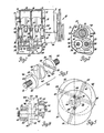
- reference numeral 10 generally indicates a four cylinder, four stroke cycle internal combustion engine having a cylinder block 11 rotatably supporting a crankshaft 12.
- the cylinder block further defines four cylinders 14 having pistons 15 reciprocably disposed therein and connected by connecting rods 16 to throws 18 of the crankshaft.
- the crankshaft is supported at longitudinally spaced bearing journals 19 by bulkheads 20 of the cylinder block having removable main bearing caps, three of which 22, 23, 24 are illustrated.
- An oil pan 26 secured to the bottom of the cylinder block encloses the lower portion of the engine crankcase and provides a sump for lubricating oil.
- the engine 10 further includes a half-speed coupling balancer 28 formed in conformity with the invention for balancing the secondary shaking force of the four cylinder four stroke engine.
- the balancer 28 is secured to the cylinder block at the longitudinal center of the engine, below the crankshaft and within the oil pan.
- the balancer includes a pair of bearing housings 30, 31 which are formed integrally with the engine main bearing caps 22, 24 and extend below and longitudinally inwardly thereof, being connected at their lower ends by a connecting plate 32.
- the rear bearing housing 30 rotatably journals a pair of laterally spaced longitudinally extending parallel shafts 34, 35 which are interconnected by like-sized gears 36, 38, respectively, mounted on the ends of the shafts 34, 35 outward of the bearing housing 30.
- Shaft 35 is also drivingly connected with the engine crankshaft by a pair of like-sized gears 39, 40 mounted on the shaft and the crankshaft respectively.
- Bearing housing 31 in turn journals a pair of laterally spaced longitudinally extending parallel shafts 42, 43. These shafts lie in a common horizontal plane with shafts 34, 35, but are laterally offset therefrom. Shaft 42 lies parallel with but laterally offset outwardly a predetermined amount from its corresponding shaft 34, while shaft 43 lies parallel to but laterally offset outwardly by the same predetermined amount from its corresponding shaft 35.
- the two sets of related, or corresponding, shafts 34, 42 and 35, 43 are interconnected by balance force producing Oldham coupling devices 44 formed in conformity with the invention.
- Coupling devices 44 as shown in Figures 3 and 4 each include a pair of end members 46, 47 rotatably connected by a coupler 48.
- End member 46 includes an input disc 50 connected with an axially extending splined input shaft 51 which is adapted to be connected with the associated balancer shaft 35.
- End member 47 likewise includes an output disc 52 having axially extending therefrom a splined output shaft 54 which is adapted to be connected with the associated balancer shaft 43.
- Coupler 48 is also constructed as a disc which lies between the input and output discs 50, 52.
- Coupler 48 is connected to discs 50, 52 by a pair of laterally extending tongues 55, 56 which project in longitudinally opposite directions from the coupler into matching grooves 58, 59 respectively formed in the input and output discs.
- the associated tongues and grooves respectively include laterally and longitudinally extending parallel surfaces 60, 62 which contact one another to apply torque and maintain the various discs in fixed angular relationship during rotation around their respective axes.
- the coupler 48 and the output disc 52 will also rotate at the same constant angular velocity.
- the geometric center 67 of the coupler 48 describes a circle 68 as it orbits around the central point 66, the circle passing through the axes 63, 64 of the input and output discs and having a diameter equal to the distance therebetween.
- the rotational orbiting speed of the center of the coupler disc 48 around its circular path 68 is a constant angular velocity exactly twice the angular velocity, or. rotational speed at which the input and output discs and the coupler are rotated. Further, while the input and output discs rotate on their geometric axes, the orbiting of the coupler disc 48 creates a rotating centrifugal force which is determined by the mass of the disc 48, the diameter of the circular orbit 68 and the speed of rotation of the coupling. This centrifugal force is thus available to be utilized for balancing opposing forces occurring in the engine or other attached mechanism and it is to this feature that the present invention is directed.
- crankshaft 12 In operation, rotation of the crankshaft 12 operating through the gear train 40, 39, 38, 36 causes opposite rotation of the parallel balancer shafts and their connected coupling devices 44.
- the associated couplers orbit in opposite directions at twice crankshaft speed and, through proper phasing, the eccentric forces of the orbiting couplers combine to provide a vertical second order shaking force having a frequency equal to twice engine speed.
- the resultant shaking force is so timed, by appropriate. physical location of the balancer elements, as to directly oppose the secondary shaking force inherent in the four cylinder four stroke engine to which the balancer is applied.
- a balancing force is developed which exactly counterbalances the secondary shaking force of the engine. This is accomplished with a balancer which is operated at the primary rotational speed of the engine. In this manner bearing friction and gear noise for a secondary vibration engine balancer are minimized.
- the half speed balancer described could be utilized to offset primary unbalance in an unbalanced mechanism by merely operating the balancer at half the cyclic unbalance speed of the mechanism and by properly arranging the eccentric weight or weights to oppose the unbalanced condition to be balanced.
- the benefits of the half speed operation of the balancer can be applied to nearly any sort of unbalanced mechanism condition.
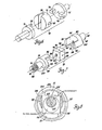
- FIG. 6 illustrates one of many possible alternative embodiments of an Oldham coupling for a half speed balancer in accordance with the invention.
- the coupling 70 has end members 71, 72 having spaced tongues 74 engaging oppositely directed grooves 75 in a connecting coupler 76.
- the operation of the construction is the same as that for the embodiment previously described in that, upon rotation of the coupling, the coupler 76 orbits at a frequency twice that of the rotational speed of the coupling itself.
- Coupling 78 includes end members 79, 80 having forklike opposed longitudinal projections 82 which extend around four sides of a cubic coupler block 83. Laterally and longitudinally extending internal surfaces 84 of the projections 82 engage the corresponding laterally and longitudinally extending outer surfaces 86 of the block 83.
- the longitudinal axes of the end members 79, 80 are offset so that, upon rotation, the coupler block 83 orbits in the manner of the previously described couplers around a circular path at an orbiting speed twice that of its rotational speed and that of the end members.
- the embodiment of Figure 7 also includes a pressure lubrication system that includes cross- drilled oil passages 87 in the bearing supported end member input and output shafts 88, 90 respectively.
- the passages 87 connect with longitudinal passages 91 that communicate through opposing conical recesses 92, 94 in opposing end faces 95,.96 of the end members and block respectively with a longitudinal passage 98 in the block.
- Passage 98 in turn connects with transverse passages 99 leading to the block outer surfaces 86.
- lubricating oil is received from the pressure-lubricated bearings supporting the input and output shafts 88, 90 of the end members 79, 80 and is delivered through the transverse passages 87 and longitudinal passages 91 to the longitudinal passage 98 of the block and thence to the lateral passages 99. From passages 99 the oil is delivered directly between opposing surfaces 84, 86 of the end members and block respectively to provide a friction reducing and cooling supply of pressure lubricant on these load carrying surfaces. Tests have shown that the use of such a pressure lubricating system provides the capability of operation at substantially higher speeds without excessive heating through friction than would otherwise be the case.
- eccentric weights exemplified by projections 100. These weights are phased to provide in combination a rotating unbalanced force, operative at the primary rotational speed of the coupling, which may be used in combination with other primary balance weights in the associated mechanism, or with additional coupling devices, to offset primary unbalance in the associated engine or other mechanism, while the rotating unbalance force of the coupler block orbiting at twice the rotational speed of the coupling is usable to offset secondary unbalance forces in the associated engine or mechanism.
- Such an application of unbalance weights could, of course, be made to shafts associated with the couplings and would be applicable to any of the arrangements previously described as well as to others.
- FIG. 8 of the drawings an unusual alternative embodiment of balancer coupling is illustrated which is suitable for mounting in an engine or mechanism in a bulkhead through which the crankshaft or other drive shaft passes.
- the arrangement includes a crankshaft 102 rotating on an axis 103.
- the crankshaft extends through a bulkhead 104 supporting a bearing 105 within an opening 106 surrounding the crankshaft and centered on an axis 107 parallel with and spaced from the crankshaft axis 103.
- a sliding block 108 is retained between opposed fork-like projections 110 forming part of the crankshaft and opposing bearing pads 111 mounted for rotation within the bearing 105 about the axis of the opening 106.
- a hole 112 through the center of the block allows passage of the crankshaft therethrough.
- crankshaft rotates the sliding block, which drives the pads 111 within bearing 105.
- This causes the block 108 to orbit in a circular path at a speed double the speed of crankshaft rotation to provide a balancing force determined by the mass of the block, the eccentricity of the orbit and the rotating speed in the same manner as in the arrangements previously described.
- Oldham coupling balancers in conformity with the present invention could be used in any suitable manner of application, utilizing one or more couplings, in which the eccentric weights of conventional shaft balancing arrangements might be ordinarily utilized.
- the construction of the coupling devices themselves may be formed in any suitable configuration capable of functioning as an Oldham coupling device in conformity with the invention.
Landscapes
- Engineering & Computer Science (AREA)
- General Engineering & Computer Science (AREA)
- Mechanical Engineering (AREA)
- Physics & Mathematics (AREA)
- Acoustics & Sound (AREA)
- Aviation & Aerospace Engineering (AREA)
- Chemical & Material Sciences (AREA)
- Combustion & Propulsion (AREA)
- Shafts, Cranks, Connecting Bars, And Related Bearings (AREA)
- Automatic Disk Changers (AREA)
- Iron Core Of Rotating Electric Machines (AREA)
- Centrifugal Separators (AREA)
Claims (5)
Applications Claiming Priority (2)
| Application Number | Priority Date | Filing Date | Title |
|---|---|---|---|
| US06/343,450 US4440123A (en) | 1982-01-28 | 1982-01-28 | Half speed balancer |
| US343450 | 1982-01-28 |
Publications (3)
| Publication Number | Publication Date |
|---|---|
| EP0085239A2 EP0085239A2 (de) | 1983-08-10 |
| EP0085239A3 EP0085239A3 (en) | 1984-04-18 |
| EP0085239B1 true EP0085239B1 (de) | 1986-10-15 |
Family
ID=23346173
Family Applications (1)
| Application Number | Title | Priority Date | Filing Date |
|---|---|---|---|
| EP82306621A Expired EP0085239B1 (de) | 1982-01-28 | 1982-12-10 | Rotierendes Ausgleichsgelenk |
Country Status (5)
| Country | Link |
|---|---|
| US (1) | US4440123A (de) |
| EP (1) | EP0085239B1 (de) |
| JP (1) | JPS58134244A (de) |
| CA (1) | CA1192802A (de) |
| DE (1) | DE3273832D1 (de) |
Families Citing this family (27)
| Publication number | Priority date | Publication date | Assignee | Title |
|---|---|---|---|---|
| US4480607A (en) * | 1983-08-01 | 1984-11-06 | General Motors Corporation | Balancer for 90 degree V6 engines and the like |
| JPS6093039U (ja) * | 1983-12-01 | 1985-06-25 | 本田技研工業株式会社 | 2サイクルエンジンにおけるバランサ装置 |
| US4576060A (en) * | 1984-10-01 | 1986-03-18 | Nicholas Gristina | Balances running on gears for a motor vehicle engine |
| GB2166842A (en) * | 1984-11-09 | 1986-05-14 | Ford Motor Co | Drive mechanism for variable valve timing |
| GB2167517A (en) * | 1984-11-27 | 1986-05-29 | Ford Motor Co | Crank mechanism |
| US4703724A (en) * | 1986-05-29 | 1987-11-03 | Chrysler Motors Corporation | Engine balancing device with a lubricant side discharge |
| US4677948A (en) * | 1986-05-29 | 1987-07-07 | Chrysler Motors Corporation | Lubricating system for an engine balancing device |
| US4703725A (en) * | 1986-05-29 | 1987-11-03 | Chrysler Motors Corporation | Mounting of an engine balancing device |
| JPS6334252A (ja) * | 1986-07-30 | 1988-02-13 | Aisin Seiki Co Ltd | 自動車用パワ−シ−ト装置 |
| JPS6477701A (en) * | 1987-09-18 | 1989-03-23 | Nissan Shatai Co | Variable capacity reciprocating piston unit |
| JPH02298601A (ja) * | 1989-05-11 | 1990-12-11 | Mitsubishi Electric Corp | スクロール流体機械 |
| GB9010685D0 (en) * | 1990-05-12 | 1990-07-04 | Concentric Pumps Ltd | I.c.engines |
| US5139461A (en) * | 1990-10-17 | 1992-08-18 | Aircraft Braking Systems Corporation | Coupler for an aircraft wheel speed transducer |
| US5259347A (en) * | 1992-06-17 | 1993-11-09 | Yamaha Hatsudoki Kabushiki Kaisha | Engine output drive arrangement |
| US5421780A (en) * | 1993-06-22 | 1995-06-06 | Vukovic; Ivan | Joint assembly permitting limited transverse component displacement |
| JP2576839B2 (ja) * | 1993-08-07 | 1997-01-29 | プロミネント ドジーアテヒニーク ゲゼルシャフト ミット ベシュレンクター ハフツング | 往復動ポンプ用のストローク調整装置 |
| KR970006985A (ko) * | 1995-07-27 | 1997-02-21 | 자동차의 크랭크 샤프트 토셔널 댐퍼 | |
| US5791309A (en) * | 1996-02-06 | 1998-08-11 | Honda Giken Kogyo Kabushiki Kaisha | Balancer shaft supporting structure in engine |
| US5907981A (en) * | 1997-04-14 | 1999-06-01 | Bell; John | Crank apparatus for a crankshaft of an internal combustion engine |
| JP3712865B2 (ja) * | 1998-08-12 | 2005-11-02 | 本田技研工業株式会社 | 往復ピストンエンジンのつり合い装置 |
| US6382166B1 (en) | 2001-01-30 | 2002-05-07 | Briggs & Stratton Corporation | Balancing system using reciprocating counterbalance weight |
| US6874458B2 (en) * | 2001-12-28 | 2005-04-05 | Kohler Co. | Balance system for single cylinder engine |
| US7004840B1 (en) * | 2002-09-17 | 2006-02-28 | Torque-Traction Technologies, Inc. | Internal balance correction device for vehicular driveshaft assembly |
| JP4313014B2 (ja) * | 2002-09-30 | 2009-08-12 | 株式会社ジェイテクト | シャフト及びその製造方法 |
| DE102004014014B4 (de) * | 2004-03-23 | 2006-06-22 | Daimlerchrysler Ag | Ausgleichswelle für einen Mehrzylinderreihenmotor |
| GB2455752B (en) * | 2007-12-20 | 2009-11-04 | Rolls Royce Plc | Developments in or relating to the balancing of a rotating assembly |
| JP6879221B2 (ja) * | 2018-01-12 | 2021-06-02 | トヨタ自動車株式会社 | 内燃機関 |
Family Cites Families (18)
| Publication number | Priority date | Publication date | Assignee | Title |
|---|---|---|---|---|
| US1807798A (en) * | 1931-06-02 | Coupling | ||
| US1459035A (en) * | 1921-06-08 | 1923-06-19 | Raisig Charles | Flexible coupling |
| US1948708A (en) * | 1933-03-09 | 1934-02-27 | John R Grundy | Flexible coupling |
| US2007513A (en) * | 1933-12-22 | 1935-07-09 | Arthur E Westburgh | Flexible coupling |
| US2214921A (en) * | 1937-04-12 | 1940-09-17 | Gen Motors Corp | Vibration suppressing means |
| US2218580A (en) * | 1937-07-02 | 1940-10-22 | Kennedy Van Saun Mfg & Eng | Tube and the like mill |
| GB572621A (en) * | 1944-01-13 | 1945-10-16 | Cav Ltd | Improvements relating to power-transmission couplings |
| US2513684A (en) * | 1945-04-20 | 1950-07-04 | American Flexible Coupling Com | Shaft coupling |
| US2498877A (en) * | 1948-10-08 | 1950-02-28 | Gen Motors Corp | Counterbalancing device |
| US3511110A (en) * | 1968-07-22 | 1970-05-12 | Deere & Co | Engine balancer |
| US3606768A (en) * | 1969-11-26 | 1971-09-21 | Ernest Wildhaber | Parallel shaft coupling |
| US3667317A (en) * | 1970-08-26 | 1972-06-06 | Int Harvester Co | Balancer |
| US3710774A (en) * | 1970-10-26 | 1973-01-16 | Allis Chalmers Mfg Co | Lube oil pump drive for balancer |
| JPS5175808A (en) * | 1974-12-26 | 1976-06-30 | Mitsubishi Motors Corp | Enjinno baransakudosochi |
| DE2822589C2 (de) * | 1978-05-24 | 1983-12-08 | Audi Nsu Auto Union Ag, 7107 Neckarsulm | Vorrichtung zum Ausgleichen der freien Massenkräfte und -momente zweiter Ordnung an einer Hubkolben-Brennkraftmaschine |
| US4300493A (en) * | 1978-07-18 | 1981-11-17 | Allis-Chalmers Corporation | Engine balancer for a four cylinder in-line internal combustion engine |
| JPS585044Y2 (ja) * | 1979-04-16 | 1983-01-28 | 日産自動車株式会社 | 内燃機関のブロ−バイガス環元装置用オイルセパレ−タ |
| DE2951092A1 (de) * | 1979-12-19 | 1981-07-02 | Fichtel & Sachs Ag, 8720 Schweinfurt | Hubkolbenmaschine mit massenausgleich |
-
1982
- 1982-01-28 US US06/343,450 patent/US4440123A/en not_active Expired - Fee Related
- 1982-11-12 CA CA000415481A patent/CA1192802A/en not_active Expired
- 1982-12-10 EP EP82306621A patent/EP0085239B1/de not_active Expired
- 1982-12-10 DE DE8282306621T patent/DE3273832D1/de not_active Expired
-
1983
- 1983-01-28 JP JP58012581A patent/JPS58134244A/ja active Pending
Also Published As
| Publication number | Publication date |
|---|---|
| DE3273832D1 (en) | 1986-11-20 |
| JPS58134244A (ja) | 1983-08-10 |
| CA1192802A (en) | 1985-09-03 |
| EP0085239A3 (en) | 1984-04-18 |
| EP0085239A2 (de) | 1983-08-10 |
| US4440123A (en) | 1984-04-03 |
Similar Documents
| Publication | Publication Date | Title |
|---|---|---|
| EP0085239B1 (de) | Rotierendes Ausgleichsgelenk | |
| EP0132943B1 (de) | Balancierungsgerät für Brennkraftmaschinen mit 6 Zylindern, die in 90-Grad-V-Form angeordnet sind | |
| US5535643A (en) | Anti-rattle engine balancer which drives associated oil pump | |
| EP0846849B1 (de) | Brennkraftmaschine mit doppeltem, kreisförmigem kulissenkurbelgetriebe | |
| US4966042A (en) | Balanced reciprocating machines | |
| CA1125124A (en) | Engine balancer for a four cylinder in-line internal combustion engine | |
| US5782213A (en) | Internal combustion engine | |
| US5875753A (en) | Balancer apparatus for engine | |
| EP0234846B1 (de) | Vorrichtung zur Ausbalancierung von Motoren mit innerer Verbrennung | |
| US5375571A (en) | Coaxially mounted engine balance shafts | |
| US4489683A (en) | Engine with crank mounted balancer for secondary shaking forces | |
| US5044333A (en) | Balancing arrangement for internal combustion engine | |
| US4936268A (en) | Balancers for multicylinder reciprocating internal combustion engines or compressors | |
| WO2000006870A9 (en) | Engine balance apparatus and accessory drive device | |
| US4132513A (en) | Rotary engine counterweight system | |
| US20030062015A1 (en) | Engine with balancer for second order pitching couple | |
| CN211737874U (zh) | 发动机及其平衡轴总成 | |
| JPS5847585B2 (ja) | 多気筒エンジンの振動防止装置 | |
| EP0640776B1 (de) | Auswuchtmechanismus für eine Brennkraftmaschine | |
| JP2000249191A (ja) | 往復動内燃機関におけるマスバランスおよび/またはモーメントバランスのための装置 | |
| JP2001153185A (ja) | ダイナミックダンパ | |
| RU2018039C1 (ru) | Устройство для уравновешивания поршневой машины | |
| JPH04307145A (ja) | 車両用直列4気筒内燃機関におけるバランサ装置 | |
| US1741570A (en) | Transmission gear for overhead engine cam shafts | |
| Ferreira et al. | Balancer shaft development for an in-line 4-Cylinder high speed diesel engine |
Legal Events
| Date | Code | Title | Description |
|---|---|---|---|
| PUAI | Public reference made under article 153(3) epc to a published international application that has entered the european phase |
Free format text: ORIGINAL CODE: 0009012 |
|
| AK | Designated contracting states |
Designated state(s): DE FR GB IT |
|
| PUAL | Search report despatched |
Free format text: ORIGINAL CODE: 0009013 |
|
| AK | Designated contracting states |
Designated state(s): DE FR GB IT |
|
| 17P | Request for examination filed |
Effective date: 19840816 |
|
| GRAA | (expected) grant |
Free format text: ORIGINAL CODE: 0009210 |
|
| ITF | It: translation for a ep patent filed | ||
| AK | Designated contracting states |
Kind code of ref document: B1 Designated state(s): DE FR GB IT |
|
| REF | Corresponds to: |
Ref document number: 3273832 Country of ref document: DE Date of ref document: 19861120 |
|
| ET | Fr: translation filed | ||
| PLBE | No opposition filed within time limit |
Free format text: ORIGINAL CODE: 0009261 |
|
| STAA | Information on the status of an ep patent application or granted ep patent |
Free format text: STATUS: NO OPPOSITION FILED WITHIN TIME LIMIT |
|
| 26N | No opposition filed | ||
| GBPC | Gb: european patent ceased through non-payment of renewal fee | ||
| PG25 | Lapsed in a contracting state [announced via postgrant information from national office to epo] |
Ref country code: FR Free format text: LAPSE BECAUSE OF NON-PAYMENT OF DUE FEES Effective date: 19880831 |
|
| PG25 | Lapsed in a contracting state [announced via postgrant information from national office to epo] |
Ref country code: DE Effective date: 19880901 |
|
| REG | Reference to a national code |
Ref country code: FR Ref legal event code: ST |
|
| PG25 | Lapsed in a contracting state [announced via postgrant information from national office to epo] |
Ref country code: GB Free format text: LAPSE BECAUSE OF NON-PAYMENT OF DUE FEES Effective date: 19881122 |