EP0085086B1 - Verfahren und anlage zur entfernung von verunreinigungen aus einem lösungsmitteldämpfe enthaltenden gasstrom - Google Patents
Verfahren und anlage zur entfernung von verunreinigungen aus einem lösungsmitteldämpfe enthaltenden gasstrom Download PDFInfo
- Publication number
- EP0085086B1 EP0085086B1 EP82902449A EP82902449A EP0085086B1 EP 0085086 B1 EP0085086 B1 EP 0085086B1 EP 82902449 A EP82902449 A EP 82902449A EP 82902449 A EP82902449 A EP 82902449A EP 0085086 B1 EP0085086 B1 EP 0085086B1
- Authority
- EP
- European Patent Office
- Prior art keywords
- solvent
- gas stream
- impurities
- washing
- process according
- Prior art date
- Legal status (The legal status is an assumption and is not a legal conclusion. Google has not performed a legal analysis and makes no representation as to the accuracy of the status listed.)
- Expired
Links
- 239000012535 impurity Substances 0.000 title claims description 41
- 238000000034 method Methods 0.000 title claims description 34
- 238000009434 installation Methods 0.000 title claims 5
- 239000002904 solvent Substances 0.000 claims description 129
- 239000007789 gas Substances 0.000 claims description 65
- 238000005406 washing Methods 0.000 claims description 55
- 239000011877 solvent mixture Substances 0.000 claims description 40
- 239000000126 substance Substances 0.000 claims description 22
- 238000009833 condensation Methods 0.000 claims description 21
- 230000005494 condensation Effects 0.000 claims description 21
- 239000002245 particle Substances 0.000 claims description 19
- 239000007788 liquid Substances 0.000 claims description 15
- 238000000926 separation method Methods 0.000 claims description 15
- 238000001179 sorption measurement Methods 0.000 claims description 14
- 239000000203 mixture Substances 0.000 claims description 10
- 238000004821 distillation Methods 0.000 claims description 7
- 239000011261 inert gas Substances 0.000 claims description 6
- 239000007787 solid Substances 0.000 claims description 6
- IJGRMHOSHXDMSA-UHFFFAOYSA-N Atomic nitrogen Chemical compound N#N IJGRMHOSHXDMSA-UHFFFAOYSA-N 0.000 claims description 4
- 230000008016 vaporization Effects 0.000 claims description 4
- 238000009834 vaporization Methods 0.000 claims description 3
- 238000010521 absorption reaction Methods 0.000 claims description 2
- 229910052757 nitrogen Inorganic materials 0.000 claims description 2
- 239000002671 adjuvant Substances 0.000 claims 2
- 238000001704 evaporation Methods 0.000 description 20
- 230000008020 evaporation Effects 0.000 description 19
- 239000000356 contaminant Substances 0.000 description 16
- OKKJLVBELUTLKV-UHFFFAOYSA-N Methanol Chemical compound OC OKKJLVBELUTLKV-UHFFFAOYSA-N 0.000 description 15
- CSCPPACGZOOCGX-UHFFFAOYSA-N Acetone Chemical compound CC(C)=O CSCPPACGZOOCGX-UHFFFAOYSA-N 0.000 description 11
- XLYOFNOQVPJJNP-UHFFFAOYSA-N water Substances O XLYOFNOQVPJJNP-UHFFFAOYSA-N 0.000 description 9
- 238000004519 manufacturing process Methods 0.000 description 7
- 229920000642 polymer Polymers 0.000 description 7
- 239000000047 product Substances 0.000 description 7
- 239000006096 absorbing agent Substances 0.000 description 5
- 239000000853 adhesive Substances 0.000 description 5
- 230000001070 adhesive effect Effects 0.000 description 5
- 238000000576 coating method Methods 0.000 description 5
- 238000002156 mixing Methods 0.000 description 5
- 239000012071 phase Substances 0.000 description 5
- 239000011347 resin Substances 0.000 description 5
- 229920005989 resin Polymers 0.000 description 5
- 239000011248 coating agent Substances 0.000 description 4
- 238000005194 fractionation Methods 0.000 description 4
- 230000002209 hydrophobic effect Effects 0.000 description 4
- 239000003921 oil Substances 0.000 description 4
- 239000000049 pigment Substances 0.000 description 4
- ZWEHNKRNPOVVGH-UHFFFAOYSA-N 2-Butanone Chemical compound CCC(C)=O ZWEHNKRNPOVVGH-UHFFFAOYSA-N 0.000 description 3
- KWYUFKZDYYNOTN-UHFFFAOYSA-M Potassium hydroxide Chemical compound [OH-].[K+] KWYUFKZDYYNOTN-UHFFFAOYSA-M 0.000 description 3
- YXFVVABEGXRONW-UHFFFAOYSA-N Toluene Chemical compound CC1=CC=CC=C1 YXFVVABEGXRONW-UHFFFAOYSA-N 0.000 description 3
- 239000002253 acid Substances 0.000 description 3
- 150000007513 acids Chemical class 0.000 description 3
- 238000009835 boiling Methods 0.000 description 3
- 239000000428 dust Substances 0.000 description 3
- 238000010438 heat treatment Methods 0.000 description 3
- 239000004033 plastic Substances 0.000 description 3
- ZGJADVGJIVEEGF-UHFFFAOYSA-M potassium;phenoxide Chemical class [K+].[O-]C1=CC=CC=C1 ZGJADVGJIVEEGF-UHFFFAOYSA-M 0.000 description 3
- 238000005507 spraying Methods 0.000 description 3
- CURLTUGMZLYLDI-UHFFFAOYSA-N Carbon dioxide Chemical compound O=C=O CURLTUGMZLYLDI-UHFFFAOYSA-N 0.000 description 2
- 239000003463 adsorbent Substances 0.000 description 2
- 239000012159 carrier gas Substances 0.000 description 2
- 239000003518 caustics Substances 0.000 description 2
- 238000006243 chemical reaction Methods 0.000 description 2
- 238000004140 cleaning Methods 0.000 description 2
- 239000012141 concentrate Substances 0.000 description 2
- 238000001816 cooling Methods 0.000 description 2
- JHIVVAPYMSGYDF-UHFFFAOYSA-N cyclohexanone Chemical compound O=C1CCCCC1 JHIVVAPYMSGYDF-UHFFFAOYSA-N 0.000 description 2
- 238000000354 decomposition reaction Methods 0.000 description 2
- 238000003795 desorption Methods 0.000 description 2
- 238000001035 drying Methods 0.000 description 2
- 230000000694 effects Effects 0.000 description 2
- 238000001914 filtration Methods 0.000 description 2
- 238000007667 floating Methods 0.000 description 2
- 239000000463 material Substances 0.000 description 2
- 239000000178 monomer Substances 0.000 description 2
- 239000012454 non-polar solvent Substances 0.000 description 2
- 239000003960 organic solvent Substances 0.000 description 2
- 239000003973 paint Substances 0.000 description 2
- ISWSIDIOOBJBQZ-UHFFFAOYSA-N phenol group Chemical group C1(=CC=CC=C1)O ISWSIDIOOBJBQZ-UHFFFAOYSA-N 0.000 description 2
- 238000012545 processing Methods 0.000 description 2
- 238000003860 storage Methods 0.000 description 2
- 238000005979 thermal decomposition reaction Methods 0.000 description 2
- 238000010626 work up procedure Methods 0.000 description 2
- FXTXRXXCMFFRTL-UHFFFAOYSA-N 4-ethyl-2-methylideneoctanoic acid Chemical compound CCCCC(CC)CC(=C)C(O)=O FXTXRXXCMFFRTL-UHFFFAOYSA-N 0.000 description 1
- 238000006887 Ullmann reaction Methods 0.000 description 1
- 239000008346 aqueous phase Substances 0.000 description 1
- 239000007900 aqueous suspension Substances 0.000 description 1
- QVGXLLKOCUKJST-UHFFFAOYSA-N atomic oxygen Chemical compound [O] QVGXLLKOCUKJST-UHFFFAOYSA-N 0.000 description 1
- 239000002585 base Substances 0.000 description 1
- 230000015572 biosynthetic process Effects 0.000 description 1
- 239000001569 carbon dioxide Substances 0.000 description 1
- 229910002092 carbon dioxide Inorganic materials 0.000 description 1
- 239000012876 carrier material Substances 0.000 description 1
- 239000003054 catalyst Substances 0.000 description 1
- 238000005119 centrifugation Methods 0.000 description 1
- 239000007795 chemical reaction product Substances 0.000 description 1
- 239000000567 combustion gas Substances 0.000 description 1
- 238000011109 contamination Methods 0.000 description 1
- 239000002826 coolant Substances 0.000 description 1
- 239000012717 electrostatic precipitator Substances 0.000 description 1
- 238000005516 engineering process Methods 0.000 description 1
- 239000002360 explosive Substances 0.000 description 1
- 206010016256 fatigue Diseases 0.000 description 1
- 239000003517 fume Substances 0.000 description 1
- 238000004817 gas chromatography Methods 0.000 description 1
- 239000001023 inorganic pigment Substances 0.000 description 1
- 230000002452 interceptive effect Effects 0.000 description 1
- 239000007791 liquid phase Substances 0.000 description 1
- 238000011068 loading method Methods 0.000 description 1
- 229910052756 noble gas Inorganic materials 0.000 description 1
- 150000002835 noble gases Chemical class 0.000 description 1
- 229920000620 organic polymer Polymers 0.000 description 1
- 229910052760 oxygen Inorganic materials 0.000 description 1
- 239000001301 oxygen Substances 0.000 description 1
- 238000010422 painting Methods 0.000 description 1
- 238000005191 phase separation Methods 0.000 description 1
- JTJMJGYZQZDUJJ-UHFFFAOYSA-N phencyclidine Chemical class C1CCCCN1C1(C=2C=CC=CC=2)CCCCC1 JTJMJGYZQZDUJJ-UHFFFAOYSA-N 0.000 description 1
- 239000002798 polar solvent Substances 0.000 description 1
- 229920000058 polyacrylate Polymers 0.000 description 1
- 238000006116 polymerization reaction Methods 0.000 description 1
- 238000001556 precipitation Methods 0.000 description 1
- 238000000746 purification Methods 0.000 description 1
- 230000001698 pyrogenic effect Effects 0.000 description 1
- 238000011084 recovery Methods 0.000 description 1
- 238000012958 reprocessing Methods 0.000 description 1
- 239000012262 resinous product Substances 0.000 description 1
- 229910000679 solder Inorganic materials 0.000 description 1
- 239000007921 spray Substances 0.000 description 1
- 238000001694 spray drying Methods 0.000 description 1
- 239000002966 varnish Substances 0.000 description 1
- 238000004018 waxing Methods 0.000 description 1
Images
Classifications
-
- B—PERFORMING OPERATIONS; TRANSPORTING
- B01—PHYSICAL OR CHEMICAL PROCESSES OR APPARATUS IN GENERAL
- B01D—SEPARATION
- B01D53/00—Separation of gases or vapours; Recovering vapours of volatile solvents from gases; Chemical or biological purification of waste gases, e.g. engine exhaust gases, smoke, fumes, flue gases, aerosols
- B01D53/14—Separation of gases or vapours; Recovering vapours of volatile solvents from gases; Chemical or biological purification of waste gases, e.g. engine exhaust gases, smoke, fumes, flue gases, aerosols by absorption
-
- B—PERFORMING OPERATIONS; TRANSPORTING
- B05—SPRAYING OR ATOMISING IN GENERAL; APPLYING FLUENT MATERIALS TO SURFACES, IN GENERAL
- B05B—SPRAYING APPARATUS; ATOMISING APPARATUS; NOZZLES
- B05B14/00—Arrangements for collecting, re-using or eliminating excess spraying material
- B05B14/40—Arrangements for collecting, re-using or eliminating excess spraying material for use in spray booths
- B05B14/49—Arrangements for collecting, re-using or eliminating excess spraying material for use in spray booths specially adapted for solvents
-
- Y—GENERAL TAGGING OF NEW TECHNOLOGICAL DEVELOPMENTS; GENERAL TAGGING OF CROSS-SECTIONAL TECHNOLOGIES SPANNING OVER SEVERAL SECTIONS OF THE IPC; TECHNICAL SUBJECTS COVERED BY FORMER USPC CROSS-REFERENCE ART COLLECTIONS [XRACs] AND DIGESTS
- Y02—TECHNOLOGIES OR APPLICATIONS FOR MITIGATION OR ADAPTATION AGAINST CLIMATE CHANGE
- Y02P—CLIMATE CHANGE MITIGATION TECHNOLOGIES IN THE PRODUCTION OR PROCESSING OF GOODS
- Y02P70/00—Climate change mitigation technologies in the production process for final industrial or consumer products
- Y02P70/10—Greenhouse gas [GHG] capture, material saving, heat recovery or other energy efficient measures, e.g. motor control, characterised by manufacturing processes, e.g. for rolling metal or metal working
Definitions
- solvents that are released in production and work processes must be recovered in addition to water.
- Such production and work processes include chemical reactions, e.g. B. polymerization reactions, precipitation reactions, thermal decomposition reactions and the like.
- the work processes include, for example, coating, impregnating or spraying any objects with solder; sung. If the solvent is removed by evaporation in a warm or hot carrier gas stream, the non-volatile or non-volatile solution components can also enter the gas stream as impurities. This danger occurs in particular when spray-drying solutions or when spraying objects with coating and impregnating solutions, eg. B. in painting technology.
- the impurities can be solid and liquid, in particular high-boiling substances, e.g. B. polymeric paint and varnish particles, residual monomers derived from polymers, catalyst substances, pigments, dust particles, products of thermal decomposition, such as tar-like and resinous products or pyrogenic products, and aggressive or corrosive substances.
- high-boiling substances e.g. B. polymeric paint and varnish particles, residual monomers derived from polymers, catalyst substances, pigments, dust particles, products of thermal decomposition, such as tar-like and resinous products or pyrogenic products, and aggressive or corrosive substances.
- the gas stream containing the solvent vapors and the contaminants must be cleaned beforehand.
- washed-out floating ponds are in many cases reusable substances, e.g. B. paint or resin particles. If these particles are in an aqueous suspension, working up is extremely difficult.
- DE-A-2 511 181 discloses a process for cleaning exhaust gases which are contaminated with organic contaminants.
- the organic impurities are washed out with the help of a high-boiling organic oil used in the liquid phase.
- These oils are usually not part of the process and must also be included in the process. If these oils are components of the process in individual cases, they are identical to the contaminants to be removed, i. H. they are not used to remove other contaminants. The oils are not intended to be recovered.
- the invention has for its object to remedy the disadvantages inherent in the known washing process and to provide a method and a system for removing impurities from a gas stream containing solvent vapors, according to which on the one hand the impurities are effectively removed and on the other hand a solvent or Solvent mixture is obtained which is reusable as far as possible without any particular effort.
- This object is achieved in that the gas stream for removing the contaminants contained therein as liquid or solid suspended particles is washed with the condensate of one or more solvent vapors contained therein, the mixture contaminated with the suspended particles in a fraction containing the contaminants and in a solvent in liquid or in Head fraction containing vapor form separates and the solvent condensate is recovered from the gas stream.
- the gas stream is preferably washed with a solvent condensate fraction which has the greatest affinity for the impurities to be removed. This not only improves the washout effect, but also the impurities are obtained in a form in which they can be returned to the process without special processing, if the substances are usable.
- resin particles have a great affinity for hydrophobic solvents, which results in an immediately reusable resin solution when washed out.
- polar substances are preferably washed out by polar solvents, non-polar substances preferably by non-polar solvents.
- the solvent is used to separate solid and liquid suspended particles and components whose dew point is above the temperature of the solvent or solvent mixture used for washing.
- the washing is preferably carried out at a temperature at which an equilibrium is established between the portions of the solvent mixture which condense and evaporate during washing. As a result, the amount of solvent in the washing process is neither reduced nor increased in this equilibrium.
- the gas stream contains the solvent or solvent mixture to be recovered in high purity or in the desired mixing ratio, so that the recovered product can be used again in the process without special work-up.
- auxiliaries which chemically and / or physically bind the impurities to be removed from the gas stream can also be added to the solvent or solvent mixture used for washing. These are primarily disruptive contaminants, e.g. B. corrosive decomposition products. For example, acids can be removed by adding alkaline substances to the solvent or solvent mixture. The reverse path is also conceivable, i. H. acids can be added to the solvent or solvent mixture to remove alkaline impurities.
- Auxiliaries that physically bind the contaminants to be removed are e.g. B. adsorbent, which can be added to the solvent or solvent mixture to remove interfering odor substances. The auxiliaries can also serve to increase the physical affinity of the solvent or solvent mixture, in order in this way to promote the complete separation of the contaminants.
- auxiliary substances which have a higher affinity for the impurities to be removed than the actual washing solvents.
- auxiliary solvents which have a higher affinity for the impurities to be removed than the actual washing solvents.
- non-polar solvents which can be added to a mixture of polar washing solvents for better removal of tar particles.
- the solvent or solvent mixture used for washing can either be returned to the process together with the separated impurities or after the impurities have been separated off.
- there are reusable contaminants e.g. B. resin or polymer particles
- impurities that are not or only to a limited extent reusable, e.g. B. decomposition products, corrosive substances or other environmentally harmful substances. These substances can, after removal of the solvent, for. B. burned or converted into other usable substances.
- the impurities can be separated off by filtering off or centrifuging if the impurities are insoluble in the solvent or have formed insoluble reaction products or adsorption complexes together with the auxiliaries which may be used.
- the solvent or solvent mixture used is then returned to the process in liquid form or used as a washing solvent.
- the impurities are separated off by distillation or fractionation, the solvent being obtained in vapor form and first being able to be fed to the gas stream, from which it is then, optionally together with the solvent vapors originally contained and the parts which evaporate during washing, by condensation and / or Adsorption can be recovered.
- condensation is sufficient, especially if the gas stream depleted of solvent vapors is returned to the process for re-loading with solvent vapors. Often, however, condensation is followed by adsorption, especially if the gas flow is discharged into the atmosphere or if it is important to return a gas flow largely freed from solvent vapors and possibly also from disturbing impurities (e.g. volatile odor substances) to the process.
- impurities e.g. volatile odor substances
- the return flow of the gas stream is particularly expedient when the gas stream is an inert gas.
- inert gases is recommended for flammable or explosive solvents.
- the preferred inert gas is nitrogen.
- noble gases, carbon dioxide and combustion gases with a reduced oxygen content can also be used.
- the separation device can be, for example, a filter or centrifugation device if the impurities are insoluble in the solvent.
- the washing solvent can be fed back into the process without further processing or used again as washing liquid, so that the condensation and / or adsorption device for condensing or adsorbing the solvent vapors from the washing device can be connected directly after this.
- the separation device is a distillation separation device in which the contaminated solvent or solvent mixture can be separated into a bottom fraction containing the contaminants and into one or more top fractions containing the solvent vapors.
- the gaseous top fraction (s) is then fed into the condensation and / or adsorption device downstream of the separation device.
- the adsorption device is preferably connected downstream of the condensation device.
- One or both of these devices have an outlet connected to an evaporation chamber for reloading the gas stream with solvent vapors for the outlet connected to solvent vapors for the gas stream which is depleted or freed of solvent vapors.
- the evaporation space can be a chamber in which an object is coated, impregnated or sprayed with a treatment solution, whereupon the solvent or solvent mixture is evaporated.
- the object to be treated can also be coated, impregnated or sprayed with the treatment solution outside the evaporation space and then brought into the evaporation space for the evaporation of the solvent or solvent mixture.
- the object to be treated is preferably heated.
- a belt dryer can also be located in the evaporation chamber, on which the objects to be dried are moved and heated, for example by radiant heaters.
- the evaporation space need not be closed on all sides, i. H. the treatment and drying can, for example, also take place under a fume hood if air is used as the carrier gas.
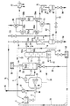
- a substance which subsequently appears as an impurity in the gas stream is mixed with the solvent or solvent mixture coming from line 6 and dissolved therein.
- the substance is, for example, a film-forming plastic or an adhesive that is soluble in organic solvents.
- the solution of the substance flows through line 8 to an atomizing nozzle 10, where it is atomized with the aid of a gas stream compressed by the compressor 12 from line 14 in the evaporation chamber 16 and sprayed onto an object 18.
- the solvent or solvent mixture evaporates in the preferably heated evaporation chamber 16.
- a cloud of floating particles is formed from the plastic or adhesive, which must be removed as contaminants from the gas stream containing solvent vapors.
- the gas flow is conducted into the washing device 24 via the suction fan 20 and the feed line 22.
- This can be a packed washing column, to which a solvent condensate obtained at least partially from the solvent vapors is fed from line 6 via a shower 26 and the feed line 28.
- Part of the solvent is supplied as fresh solvent from the reservoir 30 in order to compensate for solvent losses or to vary the composition of the solvent mixture in the desired sense.
- heating or cooling devices can also be provided in line 28 in order to adjust the temperature of the solvent supplied to the shower 26 such that the desired balance is established between the portions of the solvent mixture which condense and evaporate during washing.
- the temperature control can also be carried out by cooling or heating the washing device or the gas stream.
- Auxiliaries e.g. acids, bases or adsorbents
- These are expediently added to the fresh solvent in the storage container 30, but can also be fed into the washing device 24 at any other point.
- the washing device 24 is provided with a discharge line 32 for which the contaminants have been removed Gas stream and provided with a discharge line 34 for the solvent or solvent mixture loaded with the impurities.
- this solution e.g. a resin or adhesive solution
- this solution can be easily reused, it can be returned via the line shown in dashed lines to the mixing container 2, where it can be concentrated again by adding new plastic or adhesive .
- the solution can be returned through the line 38 shown in dashed lines to the evaporation chamber, where the solvent or solvent mixture is evaporated.
- the contaminants that remain as evaporation residue can be burned if the substances are no longer usable.
- the solution is passed via the feed line 40 into the separating device 42.
- the separating device can be, for example, a filtering or centrifuging separating device if the impurities are not soluble in the solvent or in the solvent mixture.
- the separation device 42 is a distillation separation device, i. H. a fractionation column in which the contaminated solvent or solvent mixture can be separated into a bottom fraction containing the contaminants and one or more top fractions containing the solvent vapors.
- the fractionation column can be heated by a heating coil 44 and has a discharge line 46 which leads to a collecting container 48, from which the bottom fraction can be passed either via line 36 into the mixing container 2 or via line 38 into the evaporation chamber 16, depending on the situation whether the separated impurities are reusable or not.
- the top fraction containing solvent vapors can be fed through line 50a into the line 32 from the washing device. If desired, a portion of the top fraction can be withdrawn via line 52a shown in broken lines, whereby the composition of the solvent vapors in line 32 can be varied. Multiple top fractions (shown by dashed line 50b) may also be withdrawn from separator 42, with lead 52b used in conjunction with lead 52a to determine the ratio of the individual solvent vapor fractions fed into line 32 to vary.
- the gas stream with the solvent vapors originally contained From the line 32 the gas stream with the solvent vapors originally contained, the portions evaporating during washing in the washing device 24 and the head fraction (s) from the lines 50a and 50b into the cooler 54, where the largest depending on the temperature of the coolant Part of the solvent vapors condensed out.
- the solvent condensate is collected in the separator 56 and can either be passed via the line 6 to the mixing tank 2, to the storage tank 30 or directly through the feed line 28 into the washing device 24. By adjusting the temperature in the cooler 54, further regulation of the temperature of the solvent entering the washing device 24 is possible.
- the solvent condensate can be withdrawn via line 58 when the system is to be shut down or when the solvent is to be changed.
- the condensation device consisting of the cooler 54 and the solvent separator 56 can be dispensed with.
- the gas stream laden with the solvent vapors is returned from line 32 via line 59 directly to line 14.
- the gas stream is fed via line 60 into the adsorption device consisting of adsorbers 62a and 62b, via valves 64, 66a, 68a and 70 through absorber 62a, while the content of absorber 62b, which is in a previous operating phase was loaded with solvent, is currently desorbed.
- a gas heated in the heat exchanger 72 is passed through the adsorber 62b via the valve 68b.
- the gas containing the desorbed solvent vapor flows through the valve 66b into the cooler 74, where the solvent vapors condense.
- the solvent condensate collects in the solvent separator 76 and can either be combined (via line 78) with the solvent condensate from the solvent separator 56 or removed (via line 80).
- the desorption gas is removed via line 82, or it can be circulated if it is an inert gas.
- the gas flowing into the line 14 from the absorber 62a is practically free of solvent vapors and can be used as atomizing gas in the atomizing nozzle 10.
- Fresh gas can be fed in through line 84 to compensate for inert gas losses.
- the absorber 62b When the capacity of the adsorber 62a is exhausted, the absorber 62b is switched to absorption, the gas stream laden with solvent vapors flowing from the line 60 through the valves 64 and 66b, being freed of solvent vapors in the absorber 62b and through the valves 68b and 70 in line 14 flows. At the same time, the adsorber 62a is switched to desorption, the heated gas stream flowing via the valves 68a and 66a into the cooler 74, where the solvent vapors desorbed in the adsorber 62a are condensed out.
- tanned animal skins To refine the surface of tanned animal skins, they are sprayed in a vaporization chamber similar to chamber 16 with a solution which contains a film-forming polymer and inorganic pigments in a mixture of organic solvents (cyclohexanone, toluene, methyl ethyl ketone, acetone).
- a solution which contains a film-forming polymer and inorganic pigments in a mixture of organic solvents cyclohexanone, toluene, methyl ethyl ketone, acetone.
- the gas stream sucked out of the evaporation chamber contains solvent vapors, pigment particles and spherical polymer particles.
- the gas stream is washed in the washing device 24 with acetone.
- the solvent mixture recovered from the gas stream by condensation is free of pigments and polymers and contains the solvent mixture originally used in a practically unchanged ratio.
- the concentrate of pigment and polymer obtained in the washing process in the washing device 24 makes up about 15% of the solid substances introduced into the spraying process.
- the temperature in the washing device is increased to such an extent that the viscosity of the washing liquid is in the range of the viscosity of the originally sprayed product by additional evaporation of solvent. product increases.
- the concentrate can be added to the next spray batch without further work-up.
- the impurities were not separated from the solvent mixture by distillation in a separate separating device.
- the gas stream removed from an evaporation chamber contains methanol with 4 to 6% phenolic impurities, which are used as monomers in the underlying coating process.
- Methanol with a content of 0.5 to 5% potassium hydroxide is used as the washing solution in the washing device 24.
- the formation of potassium phenolates in the washing solution reduces the phenol content in the gas stream to less than 0.1%, so that the methanol recovered from it can be returned to the production process without further separation by distillation or any other intermediate treatment.
- a needle-punched nonwoven (felt) is impregnated with the solution withdrawn from the waxing device at the end of the production process and fed to the vaporization chamber. There the methanol serving as solvent evaporates, passes into the gas stream and is recovered by condensation.
- the needle fleece with the potassium phenolates is made environmentally harmless by burning.
- the gas escaping from the evaporation chamber contains about 3% by weight (based on the polymer used) of the gas phase in addition to gasoline (bp 65 to 95 ° C) monomeric 2-ethylhexyl acrylic acid ester. Because of its higher boiling point, this is so largely removed in the gasoline-fed guard that only traces of it can be detected by gas chromatography in the solvent recovered by condensation.
- this exhaust gas stream is washed in the washing device 24 with an aqueous washing phase, acetone and water are removed almost completely from the gas phase, so that the gasoline condensed in the condensation device (54, 56) can be reused without further purification.
- the washing liquid emerging from the washing device 24 is prepared by distillation in the column 42, water being withdrawn and discarded as the bottom fraction, while acetone is recovered as the top fraction and added to the gasoline after the condensation, so that essentially the original solvent mixture can be recovered.
- the method according to the invention leads to considerable cost savings in terms of energy, material costs and disposal costs.
- the purity of the recovered solvent or solvent mixture is ensured or improved to such an extent through the selection of a suitable solvent occurring in the respective work process as washing liquid that the direct return of the solvent to the production process is possible without intermediate treatment in numerous cases.
- the components separated out in the washing process can either be returned to the production process or controlled in terms of their volume or consistency in such a way that inexpensive disposal or reprocessing is possible.
Landscapes
- Chemical & Material Sciences (AREA)
- Engineering & Computer Science (AREA)
- Analytical Chemistry (AREA)
- General Chemical & Material Sciences (AREA)
- Oil, Petroleum & Natural Gas (AREA)
- Chemical Kinetics & Catalysis (AREA)
- Vaporization, Distillation, Condensation, Sublimation, And Cold Traps (AREA)
- Treating Waste Gases (AREA)
- Gas Separation By Absorption (AREA)
- Organic Low-Molecular-Weight Compounds And Preparation Thereof (AREA)
Priority Applications (1)
| Application Number | Priority Date | Filing Date | Title |
|---|---|---|---|
| AT82902449T ATE15155T1 (de) | 1981-08-14 | 1982-08-13 | Verfahren und anlage zur entfernung von verunreinigungen aus einem loesungsmitteldaempfe enthaltenden gasstrom. |
Applications Claiming Priority (2)
| Application Number | Priority Date | Filing Date | Title |
|---|---|---|---|
| DE3132292A DE3132292C2 (de) | 1981-08-14 | 1981-08-14 | Verfahren und Anlage zur Entfernung von Verunreinigungen aus einem Lösungsmitteldämpfe enthaltenden Gasstrom |
| DE3132292 | 1981-08-14 |
Publications (2)
| Publication Number | Publication Date |
|---|---|
| EP0085086A1 EP0085086A1 (de) | 1983-08-10 |
| EP0085086B1 true EP0085086B1 (de) | 1985-08-28 |
Family
ID=6139382
Family Applications (1)
| Application Number | Title | Priority Date | Filing Date |
|---|---|---|---|
| EP82902449A Expired EP0085086B1 (de) | 1981-08-14 | 1982-08-13 | Verfahren und anlage zur entfernung von verunreinigungen aus einem lösungsmitteldämpfe enthaltenden gasstrom |
Country Status (9)
| Country | Link |
|---|---|
| US (1) | US4494967A (da) |
| EP (1) | EP0085086B1 (da) |
| JP (1) | JPS58501269A (da) |
| AU (1) | AU560085B2 (da) |
| DE (2) | DE3132292C2 (da) |
| DK (1) | DK160192C (da) |
| ES (1) | ES8308490A1 (da) |
| FI (1) | FI76500C (da) |
| WO (1) | WO1983000641A1 (da) |
Families Citing this family (30)
| Publication number | Priority date | Publication date | Assignee | Title |
|---|---|---|---|---|
| JPS60241918A (ja) * | 1984-05-16 | 1985-11-30 | Stanley Electric Co Ltd | アモルフアス・シリコン成膜プロセス中に副生成物として発生する粉塵の処理方法および装置 |
| US4708721A (en) * | 1984-12-03 | 1987-11-24 | General Signal Corporation | Solvent absorption and recovery system |
| US4753784A (en) * | 1986-03-03 | 1988-06-28 | Neverman Duane C | Process to remove SOX and NOX from exhaust gases |
| US4715965A (en) * | 1986-05-19 | 1987-12-29 | Sigerson Adam L | Method for separating and recovering volatilizable contaminants from soil |
| US4864942A (en) * | 1988-01-14 | 1989-09-12 | Chemical Waste Management Inc. | Process and apparatus for separating organic contaminants from contaminated inert materials |
| JPH01197839A (ja) * | 1988-02-02 | 1989-08-09 | Nec Corp | データ処理装置 |
| DE3904537A1 (de) * | 1989-02-15 | 1990-08-16 | Schleffler Gerhard | Verfahren zur abscheidung und entsorgung zum zwecke einer wieder- bzw. andersverwendung von spritzmaterialnebeln aus der abluft wie auch von spritzmaterialresten ueberhaupt bei verfahren zur spritzbeschichtung von gegenstaenden mit organisch-chemischen ueberzuegen |
| US5221523A (en) * | 1990-10-29 | 1993-06-22 | National Tank Company | Contaminant control system for natural gas dehydration |
| DE4036922A1 (de) * | 1990-11-20 | 1992-05-21 | Olaf Gille | Verfahren und vorrichtung zum entfernen von schadstoffen |
| US5156173A (en) * | 1991-05-14 | 1992-10-20 | Envirosolv | High-efficiency, low-emissions cleaning method and apparatus |
| US5462583A (en) * | 1994-03-04 | 1995-10-31 | Advanced Extraction Technologies, Inc. | Absorption process without external solvent |
| US6485292B1 (en) | 1999-11-19 | 2002-11-26 | Process Equipment & Service Company, Inc. | Flare stack for natural gas dehydrators |
| US6372021B1 (en) * | 2000-09-12 | 2002-04-16 | General Electric Company | Extractive removal of methanol from cumene-to-phenol process vent gas |
| US6701998B2 (en) | 2002-03-29 | 2004-03-09 | Water Gremlin Company | Multiple casting apparatus and method |
| CN100506289C (zh) * | 2002-05-27 | 2009-07-01 | 地球制药株式会社 | 挥发设备 |
| US6908640B2 (en) * | 2002-10-23 | 2005-06-21 | Water Gremlin Company | System and method for reclaiming and reuse of vehicle |
| US8701743B2 (en) | 2004-01-02 | 2014-04-22 | Water Gremlin Company | Battery parts and associated systems and methods |
| US7338539B2 (en) | 2004-01-02 | 2008-03-04 | Water Gremlin Company | Die cast battery terminal and a method of making |
| US20050203305A1 (en) * | 2004-03-11 | 2005-09-15 | Britt Michael L. | Oil extraction system |
| US8583299B2 (en) * | 2009-03-17 | 2013-11-12 | General Electric Company | System and method for communicating data in a train having one or more locomotive consists |
| PL2425478T3 (pl) | 2009-04-30 | 2019-04-30 | Water Gremlin Co | Części akumulatora mające elementy utrzymujące i uszczelniające oraz powiązane z nimi sposoby wytwarzania i zastosowanie |
| US9748551B2 (en) | 2011-06-29 | 2017-08-29 | Water Gremlin Company | Battery parts having retaining and sealing features and associated methods of manufacture and use |
| RU2505341C1 (ru) * | 2012-06-15 | 2014-01-27 | Общество с ограниченной ответственностью "НПО Пылеочистка" | Способ очистки газов |
| WO2014018752A1 (en) * | 2012-07-26 | 2014-01-30 | Badger Licensing Llc | Aromatics alkylation process |
| JP2014057935A (ja) * | 2012-09-19 | 2014-04-03 | Panasonic Corp | 排気浄化方法 |
| US9954214B2 (en) | 2013-03-15 | 2018-04-24 | Water Gremlin Company | Systems and methods for manufacturing battery parts |
| US11202983B2 (en) * | 2017-11-08 | 2021-12-21 | Btu International, Inc. | Devices, systems and methods for flux removal from furnace process gas |
| US11283141B2 (en) | 2018-12-07 | 2022-03-22 | Water Gremlin Company | Battery parts having solventless acid barriers and associated systems and methods |
| CN113521789B (zh) * | 2021-08-09 | 2022-08-26 | 聊城鲁西聚碳酸酯有限公司 | 聚碳酸酯生产过程处理有机蒸汽的装置及其方法和应用 |
| KR102646589B1 (ko) * | 2021-10-14 | 2024-03-13 | (주)맨지온 | 해수 담수화 설비 |
Family Cites Families (13)
| Publication number | Priority date | Publication date | Assignee | Title |
|---|---|---|---|---|
| GB139488A (en) * | 1916-04-07 | 1921-07-25 | George Perkins Lunt | Method of recovering solvents |
| US3324669A (en) * | 1964-06-08 | 1967-06-13 | Pittsburgh Activated Carbon Co | Lean oil contact with the regenerative medium for adsorbers |
| US3343916A (en) * | 1965-02-19 | 1967-09-26 | Exxon Research Engineering Co | Cyclic gas separation process and system |
| US3618301A (en) * | 1969-03-11 | 1971-11-09 | Clermont Engineering Co Inc | Process and apparatus for removing air pollutants from oven-stack emissions |
| IL44140A0 (en) * | 1973-04-05 | 1974-06-30 | Scm Corp | Process and apparatus for spray painting |
| DE2325421A1 (de) * | 1973-05-18 | 1974-12-05 | Linde Ag | Verfahren zur rueckgewinnung des in einem benzin-luft-gemisch enthaltenen benzins |
| DE2511181C3 (de) * | 1975-03-14 | 1978-09-14 | Daimler-Benz Ag, 7000 Stuttgart | Verfahren zur Reinigung der Abgase von Lackieranlagen |
| JPS5269869A (en) * | 1975-12-08 | 1977-06-10 | Daikin Ind Ltd | Organic solvent recovering apparatus |
| JPS5390157A (en) * | 1977-01-20 | 1978-08-08 | Sumitomo Bakelite Co Ltd | Method and apparatus for treating exhaust gas |
| US4227891A (en) * | 1979-01-29 | 1980-10-14 | Youngstown Sheet And Tube Company | Recovery of hydrocarbon vapors from air |
| US4287138A (en) * | 1979-02-02 | 1981-09-01 | Buckner Lynn A | Direct contact gaseous to liquid heat exchange and recovery system |
| US4265642A (en) * | 1979-03-01 | 1981-05-05 | Abcor, Inc. | Process of removal of solvent vapors |
| US4261707A (en) * | 1979-09-12 | 1981-04-14 | Schweitzer Industrial Corp. | Process and system for elimination of paint solvent vapors |
-
1981
- 1981-08-14 DE DE3132292A patent/DE3132292C2/de not_active Expired
-
1982
- 1982-08-13 ES ES514968A patent/ES8308490A1/es not_active Expired
- 1982-08-13 US US06/502,018 patent/US4494967A/en not_active Expired - Fee Related
- 1982-08-13 WO PCT/EP1982/000171 patent/WO1983000641A1/de not_active Ceased
- 1982-08-13 JP JP57502469A patent/JPS58501269A/ja active Pending
- 1982-08-13 EP EP82902449A patent/EP0085086B1/de not_active Expired
- 1982-08-13 DE DE8282902449T patent/DE3265848D1/de not_active Expired
- 1982-08-13 AU AU88201/82A patent/AU560085B2/en not_active Ceased
-
1983
- 1983-03-25 FI FI831034A patent/FI76500C/fi not_active IP Right Cessation
- 1983-04-13 DK DK161883A patent/DK160192C/da not_active IP Right Cessation
Also Published As
| Publication number | Publication date |
|---|---|
| DK160192C (da) | 1991-07-15 |
| JPS58501269A (ja) | 1983-08-04 |
| FI831034A0 (fi) | 1983-03-25 |
| DE3132292C2 (de) | 1986-05-07 |
| ES514968A0 (es) | 1983-09-16 |
| WO1983000641A1 (fr) | 1983-03-03 |
| DE3132292A1 (de) | 1983-03-03 |
| AU8820182A (en) | 1983-03-08 |
| AU560085B2 (en) | 1987-03-26 |
| DK161883A (da) | 1983-04-13 |
| DK161883D0 (da) | 1983-04-13 |
| DE3265848D1 (en) | 1985-10-03 |
| FI76500B (fi) | 1988-07-29 |
| EP0085086A1 (de) | 1983-08-10 |
| ES8308490A1 (es) | 1983-09-16 |
| DK160192B (da) | 1991-02-11 |
| FI76500C (fi) | 1988-11-10 |
| FI831034L (fi) | 1983-03-25 |
| US4494967A (en) | 1985-01-22 |
Similar Documents
| Publication | Publication Date | Title |
|---|---|---|
| EP0085086B1 (de) | Verfahren und anlage zur entfernung von verunreinigungen aus einem lösungsmitteldämpfe enthaltenden gasstrom | |
| EP0432812B1 (de) | Verfahren zur Reinigung von kontaminierten Böden | |
| DE3047658C2 (de) | Verfahren zur Reinigung von lösungsmittelhaltiger Abluft und Vorrichtung zur Durchführung des Verfahrens | |
| WO1995014520A1 (de) | Verfahren zur vereinfachten trennung von mehrstoffgemischen wenigstens anteilig organischen ursprungs | |
| DE3604761A1 (de) | Verfahren und vorrichtung zur behandlung von koernigen stoffen | |
| DE3612259A1 (de) | Loesemittel-eliminationsverfahren zur reinigung von luft von loesemitteldaempfen | |
| DE2645740A1 (de) | Verfahren zur beseitigung der fluessigen phase von kohlenwasserstoffen oder deren derivaten aus einem aerosol und filter zur durchfuehrung des verfahrens | |
| DE102022000536A1 (de) | Verfahren und Vorrichtung zur Behandlung von Prozessluft | |
| DE3002920A1 (de) | Verfahren zum abtrennen von autopolymerisierbaren kohlenwasserstoffdaempfen aus luft | |
| EP0641589B1 (de) | Verfahren zur selektiven Rückgewinnung von Lösemitteln aus Lösemittelgasgemischen und Vorrichtung zur Durchführung des Verfahrens | |
| DE2248279A1 (de) | Verfahren und vorrichtung zur rueckgewinnung von halogenkohlenstoffverbindungen aus oel-halogenkohlenstoffverbindungsmischungen | |
| DE3423169A1 (de) | Verfahren zur gewinnung von organischen substanzen aus gasen durch adsorption | |
| DE10150325A1 (de) | Verfahren zur Herstellung oder Beschichtung von Granulaten, Vorrichtung zur Durchführung des Verfahrens und hiernach erhältliche Granulate | |
| DE2510241A1 (de) | Verfahren zur absorption von gasfoermigen bestandteilen aus gasen | |
| DE69204420T2 (de) | Verfahren zum Entfernen von Schadstoffen aus Substrattrocknungsgas. | |
| EP0574972B1 (de) | Verfahren und Vorrichtung zur Aufbereitung von Wasserlack-Koagulat bzw. -Filtrat | |
| AT518390B1 (de) | Mehrstufiges Verfahren zur Aufbereitung von verunreinigten Reinigungslösungen und zur Trocknung der Rückstände | |
| WO2023227152A1 (de) | Verfahren und vorrichtung zur behandlung von prozessgas | |
| DE3542537A1 (de) | Verfahren und vorrichtung zur abtrennung von verunreinigungen aus einem fluidstrom | |
| DE10021951C1 (de) | Verfahren und Anlage zur Abtrennung von Heizinhaltsstoffen aus bei der Holzverarbeitung entstehenden Gasen | |
| NO156155B (no) | Fremgangsmaate og anlegg ved fjerning av forurensninger fra en gasstroem som inneholder loesningsmiddeldamper. | |
| DE102008059232A1 (de) | Verfahren und Vorrichtung zur Separation organischer Komponenten aus bei der Herstellung von Photovoltaik-Solarzellen anfallender Abluft | |
| DE3042082A1 (de) | Verfahren und vorrichtung zur wiedergewinnung von loesungsmitteln | |
| DE4116515A1 (de) | Verfahren zur abreinigung von loesungsmitteldaempfen und anderen oelloeslichen schadstoffen aus abluft und anderen gasen, und anlage zur durchfuehrung des verfahrens | |
| DE4202812A1 (de) | Verfahren zur reinigung von mit loesungsmitteln beladener abluft |
Legal Events
| Date | Code | Title | Description |
|---|---|---|---|
| PUAI | Public reference made under article 153(3) epc to a published international application that has entered the european phase |
Free format text: ORIGINAL CODE: 0009012 |
|
| 17P | Request for examination filed |
Effective date: 19830212 |
|
| AK | Designated contracting states |
Designated state(s): AT BE CH DE FR GB LI NL SE |
|
| GRAA | (expected) grant |
Free format text: ORIGINAL CODE: 0009210 |
|
| AK | Designated contracting states |
Designated state(s): AT BE CH DE FR GB LI NL SE |
|
| REF | Corresponds to: |
Ref document number: 15155 Country of ref document: AT Date of ref document: 19850915 Kind code of ref document: T |
|
| REF | Corresponds to: |
Ref document number: 3265848 Country of ref document: DE Date of ref document: 19851003 |
|
| ET | Fr: translation filed | ||
| PLBE | No opposition filed within time limit |
Free format text: ORIGINAL CODE: 0009261 |
|
| STAA | Information on the status of an ep patent application or granted ep patent |
Free format text: STATUS: NO OPPOSITION FILED WITHIN TIME LIMIT |
|
| 26N | No opposition filed | ||
| PGFP | Annual fee paid to national office [announced via postgrant information from national office to epo] |
Ref country code: DE Payment date: 19900625 Year of fee payment: 9 |
|
| PGFP | Annual fee paid to national office [announced via postgrant information from national office to epo] |
Ref country code: GB Payment date: 19900629 Year of fee payment: 9 |
|
| PGFP | Annual fee paid to national office [announced via postgrant information from national office to epo] |
Ref country code: FR Payment date: 19900706 Year of fee payment: 9 |
|
| PGFP | Annual fee paid to national office [announced via postgrant information from national office to epo] |
Ref country code: CH Payment date: 19900712 Year of fee payment: 9 |
|
| PGFP | Annual fee paid to national office [announced via postgrant information from national office to epo] |
Ref country code: SE Payment date: 19900731 Year of fee payment: 9 |
|
| PGFP | Annual fee paid to national office [announced via postgrant information from national office to epo] |
Ref country code: BE Payment date: 19900808 Year of fee payment: 9 |
|
| PGFP | Annual fee paid to national office [announced via postgrant information from national office to epo] |
Ref country code: AT Payment date: 19900813 Year of fee payment: 9 |
|
| PGFP | Annual fee paid to national office [announced via postgrant information from national office to epo] |
Ref country code: NL Payment date: 19900831 Year of fee payment: 9 |
|
| PG25 | Lapsed in a contracting state [announced via postgrant information from national office to epo] |
Ref country code: GB Effective date: 19910813 Ref country code: AT Effective date: 19910813 |
|
| PG25 | Lapsed in a contracting state [announced via postgrant information from national office to epo] |
Ref country code: SE Effective date: 19910814 |
|
| PG25 | Lapsed in a contracting state [announced via postgrant information from national office to epo] |
Ref country code: LI Effective date: 19910831 Ref country code: CH Effective date: 19910831 Ref country code: BE Effective date: 19910831 |
|
| BERE | Be: lapsed |
Owner name: LOHMANN G.M.B.H. & CO K.G. Effective date: 19910831 |
|
| PG25 | Lapsed in a contracting state [announced via postgrant information from national office to epo] |
Ref country code: NL Effective date: 19920301 |
|
| GBPC | Gb: european patent ceased through non-payment of renewal fee | ||
| NLV4 | Nl: lapsed or anulled due to non-payment of the annual fee | ||
| PG25 | Lapsed in a contracting state [announced via postgrant information from national office to epo] |
Ref country code: FR Effective date: 19920430 |
|
| REG | Reference to a national code |
Ref country code: CH Ref legal event code: PL |
|
| PG25 | Lapsed in a contracting state [announced via postgrant information from national office to epo] |
Ref country code: DE Effective date: 19920501 |
|
| REG | Reference to a national code |
Ref country code: FR Ref legal event code: ST |
|
| EUG | Se: european patent has lapsed |
Ref document number: 82902449.6 Effective date: 19920306 |