EP0084450B2 - T-Düse zum Extrudieren thermoplastischer Folien - Google Patents
T-Düse zum Extrudieren thermoplastischer Folien Download PDFInfo
- Publication number
- EP0084450B2 EP0084450B2 EP83300219A EP83300219A EP0084450B2 EP 0084450 B2 EP0084450 B2 EP 0084450B2 EP 83300219 A EP83300219 A EP 83300219A EP 83300219 A EP83300219 A EP 83300219A EP 0084450 B2 EP0084450 B2 EP 0084450B2
- Authority
- EP
- European Patent Office
- Prior art keywords
- die
- manifold
- slit
- deckle
- film
- Prior art date
- Legal status (The legal status is an assumption and is not a legal conclusion. Google has not performed a legal analysis and makes no representation as to the accuracy of the status listed.)
- Expired - Lifetime
Links
Images
Classifications
-
- B—PERFORMING OPERATIONS; TRANSPORTING
- B29—WORKING OF PLASTICS; WORKING OF SUBSTANCES IN A PLASTIC STATE IN GENERAL
- B29C—SHAPING OR JOINING OF PLASTICS; SHAPING OF MATERIAL IN A PLASTIC STATE, NOT OTHERWISE PROVIDED FOR; AFTER-TREATMENT OF THE SHAPED PRODUCTS, e.g. REPAIRING
- B29C48/00—Extrusion moulding, i.e. expressing the moulding material through a die or nozzle which imparts the desired form; Apparatus therefor
- B29C48/25—Component parts, details or accessories; Auxiliary operations
- B29C48/30—Extrusion nozzles or dies
- B29C48/305—Extrusion nozzles or dies having a wide opening, e.g. for forming sheets
- B29C48/31—Extrusion nozzles or dies having a wide opening, e.g. for forming sheets being adjustable, i.e. having adjustable exit sections
-
- B—PERFORMING OPERATIONS; TRANSPORTING
- B29—WORKING OF PLASTICS; WORKING OF SUBSTANCES IN A PLASTIC STATE IN GENERAL
- B29C—SHAPING OR JOINING OF PLASTICS; SHAPING OF MATERIAL IN A PLASTIC STATE, NOT OTHERWISE PROVIDED FOR; AFTER-TREATMENT OF THE SHAPED PRODUCTS, e.g. REPAIRING
- B29C48/00—Extrusion moulding, i.e. expressing the moulding material through a die or nozzle which imparts the desired form; Apparatus therefor
- B29C48/03—Extrusion moulding, i.e. expressing the moulding material through a die or nozzle which imparts the desired form; Apparatus therefor characterised by the shape of the extruded material at extrusion
- B29C48/07—Flat, e.g. panels
- B29C48/08—Flat, e.g. panels flexible, e.g. films
-
- B—PERFORMING OPERATIONS; TRANSPORTING
- B29—WORKING OF PLASTICS; WORKING OF SUBSTANCES IN A PLASTIC STATE IN GENERAL
- B29C—SHAPING OR JOINING OF PLASTICS; SHAPING OF MATERIAL IN A PLASTIC STATE, NOT OTHERWISE PROVIDED FOR; AFTER-TREATMENT OF THE SHAPED PRODUCTS, e.g. REPAIRING
- B29C48/00—Extrusion moulding, i.e. expressing the moulding material through a die or nozzle which imparts the desired form; Apparatus therefor
- B29C48/25—Component parts, details or accessories; Auxiliary operations
- B29C48/30—Extrusion nozzles or dies
- B29C48/305—Extrusion nozzles or dies having a wide opening, e.g. for forming sheets
Definitions
- the present invention relates to T-dies for extruding thermoplastic films for use in thermoplastic film producing equipment or laminating equipment, and more particularly to a so-called T-die of the type having a manifold formed therein and adapted to be supplied with molten resin at its center.
- T-dies for extruding thermoplastic films are conventionally known.
- such conventional T-dies offer such a disadvantage that molten resin extruded from a die slit of the conventional T-die to the atmosphere presents a neck-in phenomenon, whereby the molten resin shrinks inwardly in the widthwise direction thereof, so that edge bead portions larger in thickness than the central portion of a film are formed at opposite side edges of the film.
- edge bead portions being unusable as portions of a product, are cut away by means of a cutter or the like and waste-treated by means of a bead winder.
- the quantity of resin corresponding to the edge bead portions is entirely turned into a loss, whereby the raw material of resin is excessively consumed, thereby increasing the cost for the raw material.
- the film has to be extruded so as to have a width larger by an amount corresponding to the edge bead portions than the width of a substrate such as paper, cellophane or the like. After the extruded film is adhered onto the substrate, the edge bead portions are cut away by means of a cutter or the like.
- the edge bead portions are brought into direct contact with the pressure roll.
- the pressure roll is a rubber covered roll, to which the molten resin is easily adhered.
- a heat-resistant non-adhesiver tape Since this non-adhesive tape cannot secure a satisfactory service life against the operation for a long period of time, it is necessary to frequently replace it with new one, thus extremely deteriorating the operating efficiency. Further, such an adverse effect is rendered that chips generated at the time of cutting the edge bead portions of the film, are adhered to a product.
- the cutter being encountered with a serious wear against the use for a long period of time, is required to be frequently replaced.
- the conventional extruding metal die inevitably produces thick edge bead portions at the opposite ends of the film extruded, whereby considerable disadvantages have been given in the production of the film or the lamination.
- the present invention has been developed to obviate the above-described disadvantages of the prior art and has as its object the provision of a T-die wherein the edge bead portions at the opposite ends of the film extruded are prevented from being formed, thereby to extrude a film having a uniform thickness in the widthwise direction thereof.
- a T-die for extruding a thermoplastic film, said die comprising : a main body; a manifold defined in said body and extending in the widthwise direction of said film to be extruded ; a die slit also extending in the widthwise direction of said film and communicating with said manifold so that molten resin fed to said manifold is discharged through said die slit ; and deckle plugs each fitted in the respective end portions of said manifold and having at the inner end thereof a guide surface for guiding said molten resin so that the latter has a component of flow outwardly in the widthwise direction as it flows in the manifold to said die slit.
- edge bead portions at the opposite ends of the film extruded by the T-die As a result of study for preventing the edge bead portions at the opposite ends of the film extruded by the T-die from being formed, it has been found that the formation of the edge bead portions can be prevented by regulating the following directions of the molten resin at opposite end portions of a manifold and die slit in the T-die. More specifically, it has been found that the formation of the edge bead portions can be prevented and a film which can be fully used across its entire width obtained by guiding the molten resin at opposite ends of the T-die so that the molten resin flows gradually outwardly in the widthwise direction of the T-die throughout both the manifold and the die slit.
- each said deckle plug (6) extends into said die slit (5) with a cross-sectional shape substantially corresponding with that of the manifold (2) and the slit (5) so as to fit into said manifold and die slit for blocking said molten resin from flowing along such end portions of the manifold, each deckle plug being provided on its outer face with a deckle packing (8) to prevent molten resins from flowing between the deckle plug and the manifold wall and having its guide surface straight and and inclined outwardly in the widthwise direction in the die slit as well as in the manifold at an angle of 25° to 37° to the direction of extrusion, the guide surface extending to the point of exit or resin from the slit.
- the deckle plugs having shapes which block end portions of the manifold and die slit and which are each provided at the inner end thereof with a guide surface for guiding molten resin outwardly widthwise of the slit until the resin leaves the slit, a film can be obtained free from blemishes at its edge with consequent saving in material and with no need to remove the film edges before use.
- the provision of the straight die surface right down to the point of exit from the die slit provides for smooth flow of resin material in the manifold and die slit with a widthwise outwardly component of flow in order to achieve the benefits of the invention.
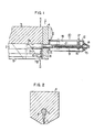
- a T-die which includes a main body 3 formed therein with a manifold 2, and side plates 4 for blocking end portions of the manifold 2.
- the manifold 2 having the substantially uniform vertically cross section extends in the longitudinal direction of the T-die and is communicated to a die slit 5 formed therealong and defined by a pairof lands. The arrangement described above is well-known.
- each deckle plug 6 has a shape of substantially blocking the manifold 2 and the die slit 5 in each end thereof and is provided at its inner end with a guide surface 7 for guiding molten resin.
- the guide surface 7 is inclined so as to guide the molten resin gradually outwardly in the widthwise direction of a film from a point 7A at the inner-most portion of the manifold 2 to a point 7B at an outlet of the die slit 5.
- the guide surface 7 is straight- lined as seen in Fig. 1.
- the deckle plug 6 is made of a soft metal such as brass and a gap of about 0.05 mm is formed between the deckle plug 6 and the inner peripheral surface of the manifold 2, so that the deckle plug 6 can move in the longitudinal direction of the manifold 2.
- a deckle packing 8 is solidly secured to the outer end of the deckle plug 6.
- the deckle packing 8 has a shape of completely blocking the gap between the deckle plug 6 and made of heat-resistant resin such for example as special fluorine plastics.
- a position adjusting device 10 for moving the deckle plug 6 is secured to the outer surface of the side plate 4.
- the adjusting device 10 comprises a slide shaft 11 secured to the deckle plug 6 and supported by the side plate 4 through a bearing 13, a support frame 12 rigidly secured to the side plate 4, an adjusting screw 14 having external threads engaging with internal threads of the slide shaft 11, and a bush 15 for rotatably supporting the adjusting screw 14.
- rotation of the adjusting screw 14 moves the slide shaft to adjust the widthwise position of the deckle plug 6.
- a ring 16 and a guide pin 17 are secured to the slide shaft 11.
- the guide pin 17 projects to outside through a slot 18 formed on the upper surface of the support frame 12, and a graduation, not shown, for indicating the position of the guide pin 17 is provided by the slot 18.
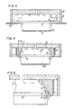
- Fig. 3 shows the typical T-die of the prior art, in which outer deckles 20 for regulating a discharge width are mounted outside the die slit 5.
- the flows of the molten resin as indicated by arrows are considered to be occurred in the T-die of the above-described arrangement.
- the molten resin extruded from the die slit 5 is formed into a film 21, shrinking in the widthwise direction thereof, due to a neck-in phenomenon.
- the film 21 formed has edge bead portions 22 at opposite side edges thereof.
- the edge bead portion is more than three times larger in thickness than the other portion.
- edge bead portions are formed as such that the widthwise shrinkage of the discharged film at the end portions thereof is larger in value than that at the central portion thereof and the discharged volumes of the molten resin at the end portions A of the die slit 5 are larger than the discharged volume of the molten resin at the central portion.
- the edge bead portions are still formed.
- the deckle plugs 6 each having an inclined guide surface 7 are inserted into the manifold 2 and die slit 5, and hence, the molten resin discharged from the opposite ends of the slit is considered to flow as indicated by arrows D and E in the manifold 2.
- the molten resin discharged from the land of this T-die immediately shrinks in the widthwise direction due to the neck-in phenomenon, but the film 23 thus formed has a thickness uniform in the widthwise direction, and has substantially no edge bead portions 22 as seen with the conventional die. The reason for this is not accurately known, but the following may form the reason.
- the manifold 2 above the end portions F of the die slit 2 is blocked by the deckle plugs 6 as shown in Fig. 5, whereby the vertical sectional area of the manifold 2 is decreased gradually outwardly in the widthwise direction of the film.
- the flowing resistances to the resin flowing at the end portions F are larger that in the center portion, whereby the flow rates of the resin in the end portions F are lower than the flow rate to the central portion.
- the flow is divided into two including a flow G flowing along the guide surface 7 and a flow H being returned to the direction of the center due to the neck-in phenomenon of the film, whereby the flow rate of the resin discharged from the end portions F of the die slit 5 becomes very low.
- the thickness of the film finally formed becomes substantially constant.
- the deckle plugs each having a guide surface for guiding the flow of the molten resin obliquely outwardly, into the end portions of the manifold and die slit of the T-die makes it possible to easily form a film having a substantially uniform thickness.
- necessity for cutting and removing the edge bead portions formed at the side edge portions of the film as in the prior art can be eliminated, the whole width of the film is available as a product, and various disadvantages which have been encountered by the formation of the edge bead portions can be obviated.
- the deckle plug has a function of regulating the width of the film extruded, thereby to eliminate necessity for using the outer deckles 20 in the prior art (Refer to Fig. 3).
- the position adjusting device 10 for adjusting the position of the deckle plug 6 from outside of the die in the assembled state of the die.
- the position adjusting device 10 may be dispensed with.
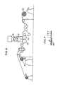
- the laminater system used comprises a winding-off device 30, an extruder 31, a T-die 32, a chill roll 33, a pressure roll 34, a cutter 35 for cutting edge bead portions, a winder 36, a winder 37 for winding edge bead portions and the like.
- the average thickness of the selvedge was 0.073 or 0.085 mm, which was about 2.8 times the required coating thickness (the coating thickness at the central portion) of 0.026 mm.
- the thickness of the film selvedges in average value was 0.028 or 0.033 mm, which was fully within the tolerance scope of the product. As a consequence, necessity for putting the film selvedges outwardly of the width of the base was eliminated.
Landscapes
- Engineering & Computer Science (AREA)
- Mechanical Engineering (AREA)
- Manufacturing & Machinery (AREA)
- Extrusion Moulding Of Plastics Or The Like (AREA)
Claims (2)
Applications Claiming Priority (2)
| Application Number | Priority Date | Filing Date | Title |
|---|---|---|---|
| JP7362/82 | 1982-01-20 | ||
| JP57007362A JPS58124618A (ja) | 1982-01-20 | 1982-01-20 | 熱可塑性フイルム押出成形用tダイ |
Publications (3)
| Publication Number | Publication Date |
|---|---|
| EP0084450A1 EP0084450A1 (de) | 1983-07-27 |
| EP0084450B1 EP0084450B1 (de) | 1986-05-28 |
| EP0084450B2 true EP0084450B2 (de) | 1991-05-02 |
Family
ID=11663847
Family Applications (1)
| Application Number | Title | Priority Date | Filing Date |
|---|---|---|---|
| EP83300219A Expired - Lifetime EP0084450B2 (de) | 1982-01-20 | 1983-01-17 | T-Düse zum Extrudieren thermoplastischer Folien |
Country Status (7)
| Country | Link |
|---|---|
| EP (1) | EP0084450B2 (de) |
| JP (1) | JPS58124618A (de) |
| AU (1) | AU556108B2 (de) |
| BR (1) | BR8300062A (de) |
| DE (1) | DE3363617D1 (de) |
| GB (1) | GB2114050B (de) |
| MX (1) | MX161981A (de) |
Families Citing this family (13)
| Publication number | Priority date | Publication date | Assignee | Title |
|---|---|---|---|---|
| JPS60191419U (ja) * | 1984-05-31 | 1985-12-19 | 大日本印刷株式会社 | Tダイス巾調整装置 |
| JPH0696260B2 (ja) * | 1988-08-11 | 1994-11-30 | ダイアホイルヘキスト株式会社 | 重合体フィルムの製造方法 |
| US5234330A (en) * | 1991-06-14 | 1993-08-10 | Eastman Kodak Company | Dies |
| US5458838A (en) * | 1992-03-11 | 1995-10-17 | Kabushiki Kaisha Kobe Seiko Sho | Heating and extruding method for bulk preform |
| EP0579142B1 (de) * | 1992-07-17 | 1997-11-19 | The Cloeren Company | Interne Randbegrenzungsvorrichtung |
| US5582850A (en) * | 1992-10-27 | 1996-12-10 | The Cloeren Company | Internal deckle position control |
| US5511962A (en) * | 1993-02-01 | 1996-04-30 | Extrusion Dies, Inc. | Extrusion die |
| JPH0747587A (ja) * | 1993-08-06 | 1995-02-21 | Johoku Seikosho:Kk | Tダイ |
| US5451357A (en) * | 1993-08-26 | 1995-09-19 | The Cloeren Company | Apparatus and process for composite extrusion with width adjustment |
| US5843530A (en) * | 1997-01-21 | 1998-12-01 | Minnesota Mining And Manufacturing Company | Method for minimizing waste when coating a fluid with a slide coater |
| FI107321B (fi) * | 1998-04-07 | 2001-07-13 | Nextrom Holding Sa | Menetelmä ja laite muovikalvon valmistamiseksi |
| JP4280486B2 (ja) | 2002-11-25 | 2009-06-17 | 富士フイルム株式会社 | 溶液製膜方法 |
| CN120396212B (zh) * | 2025-07-03 | 2025-08-29 | 潍坊煜达电声科技有限公司 | 一种声学弹性薄膜制造设备 |
Family Cites Families (2)
| Publication number | Priority date | Publication date | Assignee | Title |
|---|---|---|---|---|
| JPS5472267A (en) * | 1977-11-21 | 1979-06-09 | Nishitami Kougiyou Kk | Method of extruding film |
| US4248579A (en) | 1979-10-10 | 1981-02-03 | Jyohoku Seiko Co., Ltd. | Film extrusion die |
-
1982
- 1982-01-20 JP JP57007362A patent/JPS58124618A/ja active Pending
-
1983
- 1983-01-07 BR BR8300062A patent/BR8300062A/pt unknown
- 1983-01-10 MX MX195874A patent/MX161981A/es unknown
- 1983-01-10 AU AU10246/83A patent/AU556108B2/en not_active Ceased
- 1983-01-17 EP EP83300219A patent/EP0084450B2/de not_active Expired - Lifetime
- 1983-01-17 GB GB08301204A patent/GB2114050B/en not_active Expired
- 1983-01-17 DE DE8383300219T patent/DE3363617D1/de not_active Expired
Also Published As
| Publication number | Publication date |
|---|---|
| GB2114050B (en) | 1985-12-18 |
| GB2114050A (en) | 1983-08-17 |
| DE3363617D1 (en) | 1986-07-03 |
| AU1024683A (en) | 1983-07-28 |
| AU556108B2 (en) | 1986-10-23 |
| EP0084450A1 (de) | 1983-07-27 |
| EP0084450B1 (de) | 1986-05-28 |
| JPS58124618A (ja) | 1983-07-25 |
| MX161981A (es) | 1991-03-14 |
| BR8300062A (pt) | 1983-09-20 |
| GB8301204D0 (en) | 1983-02-16 |
Similar Documents
| Publication | Publication Date | Title |
|---|---|---|
| EP0084450B2 (de) | T-Düse zum Extrudieren thermoplastischer Folien | |
| US4424762A (en) | Coating apparatus | |
| JP2598617B2 (ja) | 熱可塑材料用の押出し成型装置 | |
| EP0579142B1 (de) | Interne Randbegrenzungsvorrichtung | |
| US6495081B2 (en) | Method for manufacturing tread bands for vehicle tires | |
| JPH0631789A (ja) | 複数層重合体フィルムの製造方法及び装置 | |
| CA1230718A (en) | Valve plate and feedblock design for co-extrusion apparatus and co-extrusion process using same | |
| US4217322A (en) | Process for extruding synthetic resin and die for use therein | |
| JPS6119344A (ja) | 自動車タイヤのトレツド、他の成形体またはシートの製造装置 | |
| US7090479B2 (en) | Apparatus and method for manufacturing resin molded product | |
| MXPA96005130A (en) | Method and apparatus for cladding in combination, by rolling and troquel, with better trimming | |
| EP0464790B1 (de) | Verfahren und Vorrichtung zur Herstellung einer thermoplastischen Harzschicht | |
| JPS5839419A (ja) | カラ−ウエツジフイルムを製造する方法及びその装置 | |
| EP2979841A1 (de) | Reinigungswalze, vorrichtung zur herstellung einer kunststofffolie damit und herstellungsverfahren | |
| US5830391A (en) | Adjustable, leak-free sealing device for polymer dies | |
| US6461138B2 (en) | Device for forming multilayer sheets and extrusion die therefor | |
| EP0781641A2 (de) | Verfahren zur Herstellung von Mehrschichtbahn oder Folie und Extrusionsdüse | |
| US3694132A (en) | Extrusion die deckle means | |
| US5376178A (en) | Coating apparatus | |
| US3684422A (en) | Fishtail die for producing thermoplastic films and sheets | |
| US4576563A (en) | Rotary roll-type rubber extruder | |
| US20190315035A1 (en) | Dual stage flex lip for an extrusion die | |
| EP1084019B1 (de) | Einstellbarer leckfreier dichtungsvorrichtung für kunststoffdüsen | |
| AU2772592A (en) | Hopper edge guide system | |
| CN215921080U (zh) | 一种宽胶片成型设备 |
Legal Events
| Date | Code | Title | Description |
|---|---|---|---|
| PUAI | Public reference made under article 153(3) epc to a published international application that has entered the european phase |
Free format text: ORIGINAL CODE: 0009012 |
|
| AK | Designated contracting states |
Designated state(s): BE CH DE FR GB IT LI NL SE |
|
| 17P | Request for examination filed |
Effective date: 19831126 |
|
| GRAA | (expected) grant |
Free format text: ORIGINAL CODE: 0009210 |
|
| AK | Designated contracting states |
Kind code of ref document: B1 Designated state(s): BE CH DE FR GB IT LI NL SE |
|
| ITF | It: translation for a ep patent filed | ||
| REF | Corresponds to: |
Ref document number: 3363617 Country of ref document: DE Date of ref document: 19860703 |
|
| ET | Fr: translation filed | ||
| PLBI | Opposition filed |
Free format text: ORIGINAL CODE: 0009260 |
|
| 26 | Opposition filed |
Opponent name: HERMANN BERSTORFF MASCHINENBAU GMBH Effective date: 19861128 |
|
| NLR1 | Nl: opposition has been filed with the epo |
Opponent name: HERMANN BERSTORFF MASCHINENBAU GMBH |
|
| PUAH | Patent maintained in amended form |
Free format text: ORIGINAL CODE: 0009272 |
|
| STAA | Information on the status of an ep patent application or granted ep patent |
Free format text: STATUS: PATENT MAINTAINED AS AMENDED |
|
| 27A | Patent maintained in amended form |
Effective date: 19910502 |
|
| AK | Designated contracting states |
Kind code of ref document: B2 Designated state(s): BE CH DE FR GB IT LI NL SE |
|
| ITF | It: translation for a ep patent filed | ||
| ET3 | Fr: translation filed ** decision concerning opposition | ||
| NLR2 | Nl: decision of opposition | ||
| NLR3 | Nl: receipt of modified translations in the netherlands language after an opposition procedure | ||
| ITTA | It: last paid annual fee | ||
| EAL | Se: european patent in force in sweden |
Ref document number: 83300219.9 |
|
| PGFP | Annual fee paid to national office [announced via postgrant information from national office to epo] |
Ref country code: FR Payment date: 19971218 Year of fee payment: 16 |
|
| PGFP | Annual fee paid to national office [announced via postgrant information from national office to epo] |
Ref country code: SE Payment date: 19971219 Year of fee payment: 16 |
|
| PGFP | Annual fee paid to national office [announced via postgrant information from national office to epo] |
Ref country code: DE Payment date: 19971222 Year of fee payment: 16 Ref country code: NL Payment date: 19971222 Year of fee payment: 16 |
|
| PGFP | Annual fee paid to national office [announced via postgrant information from national office to epo] |
Ref country code: GB Payment date: 19971223 Year of fee payment: 16 |
|
| PGFP | Annual fee paid to national office [announced via postgrant information from national office to epo] |
Ref country code: CH Payment date: 19980108 Year of fee payment: 16 |
|
| PGFP | Annual fee paid to national office [announced via postgrant information from national office to epo] |
Ref country code: BE Payment date: 19980115 Year of fee payment: 16 |
|
| PG25 | Lapsed in a contracting state [announced via postgrant information from national office to epo] |
Ref country code: GB Free format text: LAPSE BECAUSE OF NON-PAYMENT OF DUE FEES Effective date: 19990117 |
|
| PG25 | Lapsed in a contracting state [announced via postgrant information from national office to epo] |
Ref country code: SE Free format text: LAPSE BECAUSE OF NON-PAYMENT OF DUE FEES Effective date: 19990118 |
|
| PG25 | Lapsed in a contracting state [announced via postgrant information from national office to epo] |
Ref country code: CH Free format text: LAPSE BECAUSE OF NON-PAYMENT OF DUE FEES Effective date: 19990131 Ref country code: LI Free format text: LAPSE BECAUSE OF NON-PAYMENT OF DUE FEES Effective date: 19990131 Ref country code: BE Free format text: LAPSE BECAUSE OF NON-PAYMENT OF DUE FEES Effective date: 19990131 |
|
| BERE | Be: lapsed |
Owner name: TETRA PAK INTERNATIONAL A.B. Effective date: 19990131 |
|
| PG25 | Lapsed in a contracting state [announced via postgrant information from national office to epo] |
Ref country code: NL Free format text: LAPSE BECAUSE OF NON-PAYMENT OF DUE FEES Effective date: 19990801 |
|
| GBPC | Gb: european patent ceased through non-payment of renewal fee |
Effective date: 19990117 |
|
| REG | Reference to a national code |
Ref country code: CH Ref legal event code: PL |
|
| PG25 | Lapsed in a contracting state [announced via postgrant information from national office to epo] |
Ref country code: FR Free format text: LAPSE BECAUSE OF NON-PAYMENT OF DUE FEES Effective date: 19990930 |
|
| PG25 | Lapsed in a contracting state [announced via postgrant information from national office to epo] |
Ref country code: DE Free format text: LAPSE BECAUSE OF NON-PAYMENT OF DUE FEES Effective date: 19991103 |
|
| REG | Reference to a national code |
Ref country code: FR Ref legal event code: ST |
|
| APAH | Appeal reference modified |
Free format text: ORIGINAL CODE: EPIDOSCREFNO |