EP0084006B1 - Electric cooking range - Google Patents
Electric cooking range Download PDFInfo
- Publication number
- EP0084006B1 EP0084006B1 EP19830400030 EP83400030A EP0084006B1 EP 0084006 B1 EP0084006 B1 EP 0084006B1 EP 19830400030 EP19830400030 EP 19830400030 EP 83400030 A EP83400030 A EP 83400030A EP 0084006 B1 EP0084006 B1 EP 0084006B1
- Authority
- EP
- European Patent Office
- Prior art keywords
- heating element
- fan
- turbine
- oven
- muffle
- Prior art date
- Legal status (The legal status is an assumption and is not a legal conclusion. Google has not performed a legal analysis and makes no representation as to the accuracy of the status listed.)
- Expired
Links
Images

Classifications
-
- F—MECHANICAL ENGINEERING; LIGHTING; HEATING; WEAPONS; BLASTING
- F24—HEATING; RANGES; VENTILATING
- F24C—DOMESTIC STOVES OR RANGES ; DETAILS OF DOMESTIC STOVES OR RANGES, OF GENERAL APPLICATION
- F24C15/00—Details
- F24C15/32—Arrangements of ducts for hot gases, e.g. in or around baking ovens
- F24C15/322—Arrangements of ducts for hot gases, e.g. in or around baking ovens with forced circulation
- F24C15/325—Arrangements of ducts for hot gases, e.g. in or around baking ovens with forced circulation electrically-heated
Definitions
- the present invention relates to domestic electric cooking ovens of the type comprising a muffle in which are mounted at least one vault heating element, at least one hearth heating element, an air circulation turbine provided in the rear wall. muffle, a heating element placed in the air flow stream of the turbine, an air ducting means arranged to direct the air blown by the turbine in roughly horizontal veins in the cavity of the muffle, and an electrical switching device for the selective energization of said heating elements and said turbine.
- Such ovens have already been described for example in DE-A-2 657 929. Their switching device is arranged. so that the user can place the oven in a first configuration called “conventional”, in which are energized exclusively, the vault and bottom elements and also in a second configuration, in which only the heating element of the turbine and this turbine itself is in action.
- This second configuration is commonly called “fan heat”.
- the object of the invention is to provide a domestic cooking oven of the type defined above, but without the abovementioned drawbacks.
- this oven is characterized in that said switching device comprises a position in which it is able to connect said turbine heating element in series with the roof heating element or elements, while energizing said turbine and said bottom heating element, in parallel with said elements connected in series.
- the oven can be placed in a so-called mixed configuration in which the hearth heating element operates at full power, while the vault and turbine heating elements consume only a relatively low power, the heat which they generate being conveyed in any ia cavity of the furnace.
- the dish receives a high amount of heat from below by radiation and convection (for example for cooking a moist pie shell) while the sum of the heat supplied by the other resistances leads to a shorter cooking time than would be necessary in the other configurations of the oven. This therefore not only results in a better culinary result, but also a saving of up to 8% for a moist pastry in comparison with the fan-assisted configuration.
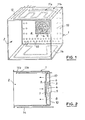
- FIGs. 1 and 2 there is shown schematically an oven muffle 1 delimiting a cooking cavity 2 which, of course, is closed by a door (not shown) during cooking.
- a turbine 4 driven by an electric motor 5, the discharge openings of the turbine being surrounded by a turbine resistor 6 formed for example by two coaxial turns.
- the suction side of the turbine is placed in front of the central opening 7 of an air duct plate 8 in front of which a filter 9 is mounted.
- the duct plate 8 has discharge orifices 10 at its periphery.
- Arch heating elements 11 a and 11 b are mounted at the top of the muffle parallel to its arch wall.
- a temperature sensor 12 controlling a thermostat contact 13 is placed next to the roof resistor 11 b.
- a hearth heating element 14 or hearth resistance is arranged below the bottom wall of the muffle 1.
- Contact A is connected to terminal 15 and is connected in series with the rest of the circuit to control power-up or cut-off.
- the motor 5 of the turbine 4 is connected in series with the contact B between the contact A and the terminal 16.
- the thermostatic contact 13 reacting to the probe 12 is connected between the contact A and a circuit which includes the heating elements of the oven .
- the turbine heating element 6 is connected between the thermostatic contact 13 and a junction point 17 to which the grill and arch elements 11 a and 11b are connected in series with the respective contacts D and F, all being connected in parallel to contact E of the switching means.
- the floor resistor 14 is mounted in series with the contact G between the contact 13 and the terminal 16.
- FIG. 4 shows that the oven according to the invention can be placed, by means of a simple switching with a single button, not only in the conventional configurations such as “fan heat and” conventional “(positions c and i), but also in a so-called configuration "Mixed during which the oven is heated by the hearth resistance 14 providing a significant amount of heat from the bottom of the muffle and by the series connection of the turbine resistance 6 on the one hand and the parallel connection of the resistors of the vault 11a a and 11b on the other hand, the heat generated of which is conveyed and regularly distributed in the muffle thanks to the rotation of the turbine 4. This is here position d of FIG. 4.
- the oven according to the invention therefore combines all the advantages of the two conventional cooking methods mentioned above as well as those resulting from the third "mixed" configuration. These particular advantages are in particular a better horizontal distribution of the heat in the oven, the contribution of calories being better distributed in particular by placing the floor resistance in series and paralleling the vault resistors in series with the turbine resistance.
- Fig. 5 shows by way of comparison two diagrams of the temperature as a function of the time corresponding to the baking of a pastry of the aforementioned kind.
- Diagram (a) shows the energy expenditure for the "circulating heat” configuration (position c), while diagram (b) shows this expenditure in mixed configuration (position d).
Landscapes
- Engineering & Computer Science (AREA)
- Chemical & Material Sciences (AREA)
- Combustion & Propulsion (AREA)
- Mechanical Engineering (AREA)
- General Engineering & Computer Science (AREA)
- Baking, Grill, Roasting (AREA)
Description
La présente invention est relative aux fours électriques de cuisson domestiques du type comportant un moufle dans lequel sont montés au moins un élément de chauffage de voûte, au moins un élément de chauffage de sole, une turbine de circulation d'air prévue dans la paroi arrière du moufle, un élément de chauffage placé dans le courant de circulation d'air de la turbine, un moyen de canalisation d'air agencé pour orienter l'air pulsé par la turbine selon des veines à peu près horizontales dans la cavité du moufle, ainsi qu'un dispositif de commutation électrique pour la mise sous tension sélective desdits éléments de chauffage et de ladite turbine.The present invention relates to domestic electric cooking ovens of the type comprising a muffle in which are mounted at least one vault heating element, at least one hearth heating element, an air circulation turbine provided in the rear wall. muffle, a heating element placed in the air flow stream of the turbine, an air ducting means arranged to direct the air blown by the turbine in roughly horizontal veins in the cavity of the muffle, and an electrical switching device for the selective energization of said heating elements and said turbine.
De tels fours ont déjà été décrits par exemple dans DE-A-2 657 929. Leur dispositif de commutation est agencé. pour que l'utilisateur puisse placer le four dans une première configuration dite « conventionnelle », dans laquelle sont mis sous tension exclusivement, les éléments de voûte et de sole et également dans une seconde configuration, dans laquelle seuls l'élément de chauffage de la turbine et cette turbine elle-même sont en action. Cette seconde configuration est appelée communément « à chaleur tournante •.Such ovens have already been described for example in DE-A-2 657 929. Their switching device is arranged. so that the user can place the oven in a first configuration called "conventional", in which are energized exclusively, the vault and bottom elements and also in a second configuration, in which only the heating element of the turbine and this turbine itself is in action. This second configuration is commonly called "fan heat".
Dans un tel four, on peut donc regrouper les avantages des deux types de cuisson, c'est-à-dire en configuration conventionnelle, on obtient de bons résultats avec des viandes et des résultats plutôt moins bons avec des pâtisseries (avec quasi-impossibilité de cuire à plusieurs niveaux à la fois dans le four), tandis qu'en configuration à chaleur tournante, ce sont plutôt les pâtisseries sèches qui réussissent le mieux avec l'avantage non négligeable que l'on peut faire cuire simultanément à plusieurs niveaux.In such an oven, we can therefore combine the advantages of the two types of cooking, that is to say in a conventional configuration, we obtain good results with meats and rather less good results with pastries (with almost impossible to bake on several levels at the same time in the oven), while in a fan-assisted configuration, it is rather the dry pastries that are most successful with the significant advantage that one can bake simultaneously on several levels.
Néanmoins, ce four présente certains inconvénients qui sont les suivants :
- 1) Certaines pâtisseries, notamment les tartes à fruits dites « humides avec pâte feuilletée ou brisée, ne sont pas suffisamment cuites par en dessous.
Il faut alors avoir recours à certains artifices pour arriver à un bon résultat, ce qui demande un certain savoir-faire.
- 2) Pour la cuisson à un seul niveau, on ne peut avoir recours qu'à l'une ou l'autre des configurations, ce qui amène à choisir un temps de cuisson relativement élevé d'où une consommation en énergie importante.
- 3) La répartition horizontale de l'énergie n'est pas aussi uniforme que l'on pourrait le souhaiter en configuration à chaleur tournante, cette répartition étant passable en configuration conventionnelle.
- 1) Certain pastries, in particular fruit tarts known as "wet with puff pastry or shortcrust pastry," are not sufficiently cooked from below.
It is then necessary to have recourse to certain devices to arrive at a good result, which requires a certain know-how.
- 2) For cooking at a single level, only one or other of the configurations can be used, which leads to choosing a relatively high cooking time, hence a significant energy consumption.
- 3) The horizontal distribution of energy is not as uniform as one might wish in a fan-assisted configuration, this distribution being passable in conventional configuration.
En outre, dans DE-A-2 658 686, on a décrit un four dans lequel un élément de chauffage de turbine est sous tension en même temps qu'un élément de chauffage de voûte et éventuellement un élément de chauffage de sole. Mais ce document ne prévoit pas un chauffage de sole plus important.In addition, in DE-A-2 658 686, an oven has been described in which a turbine heating element is energized at the same time as a roof heating element and possibly a hearth heating element. However, this document does not provide for greater heating of the sole.
L'invention a pour but de fournir un four de cuisson domestique du type défini ci-dessus, mais dépourvu des inconvénients précités.The object of the invention is to provide a domestic cooking oven of the type defined above, but without the abovementioned drawbacks.
Suivant l'invention, ce four est caractérisé en ce que ledit dispositif de commutation comporte une position dans laquelle il est capable de brancher ledit élément de chauffage de turbine en série avec le ou les éléments de chauffage de voûte, tout en mettant sous tension ladite turbine et ledit élément de chauffage de sole, en parallèle desdits éléments branchés en série.According to the invention, this oven is characterized in that said switching device comprises a position in which it is able to connect said turbine heating element in series with the roof heating element or elements, while energizing said turbine and said bottom heating element, in parallel with said elements connected in series.
Grâce à ces caractéristiques, le four peut être placé dans une configuration dite mixte dans laquelle l'élément de chauffage de sole fonctionne à pleine puissance, tandis que les éléments de chauffage de voûte et de turbine ne consomment qu'une puissance relativement faible, la chaleur qu'ils engendrent étant véhiculée dans toute ia cavité du four. Il en résulte que, dans l'hypothèse d'une cuisson à un seul niveau, le mets reçoit une quantité de chaleur élevée par en dessous par rayonnement et convection (par exemple pour la cuisson d'un fond de tarte humide) alors que la somme de la chaleur fournie par les autres résistances conduit à un temps de cuisson plus bref qu'il n'en serait nécessaire dans les autres configurations du four. Il s'ensuit donc non seulement un meilleur résultat culinaire, mais également une économie pouvant aller jusqu'à 8 % pour une pâtisserie humide en comparaison avec la configuration à chaleur tournante.Thanks to these characteristics, the oven can be placed in a so-called mixed configuration in which the hearth heating element operates at full power, while the vault and turbine heating elements consume only a relatively low power, the heat which they generate being conveyed in any ia cavity of the furnace. As a result, in the case of cooking at one level, the dish receives a high amount of heat from below by radiation and convection (for example for cooking a moist pie shell) while the sum of the heat supplied by the other resistances leads to a shorter cooking time than would be necessary in the other configurations of the oven. This therefore not only results in a better culinary result, but also a saving of up to 8% for a moist pastry in comparison with the fan-assisted configuration.
L'invention est exposée ci-après plus en détail à l'aide de dessins représentant seulement un mode d'exécution, sur lesquels :
- la Figure 1 est une vue en perspective très simplifiée d'un four réalisé conformément aux caractéristiques de l'invention ;
- la Figure 2 montre une vue en coupe verticale de ce four ;
- la Figure 3 montre également de façon très simplifiée un schéma électrique du four ;
- la Figure 4 est un diagramme de fonctionnement du dispositif de commutation monté sur le four suivant l'invention ; et
- la Figure 5 montre par des graphiques de la température en fonction du temps, les dépenses en énergie lorsque le four est en configuration à la chaleur tournante d'une part, et en configuration mixte, d'autre part.
- Figure 1 is a very simplified perspective view of an oven produced in accordance with the characteristics of the invention;
- Figure 2 shows a vertical sectional view of this oven;
- Figure 3 also very schematically shows an electrical diagram of the oven;
- Figure 4 is an operating diagram of the switching device mounted on the oven according to the invention; and
- FIG. 5 shows, by graphs of the temperature as a function of time, the energy expenditure when the oven is in the circulating heat configuration on the one hand, and in the mixed configuration, on the other hand.
On se référera tout d'abord aux Fig. 1 et 2 sur lesquelles on a représenté schématiquement un moufle de four 1 délimitant une cavité de cuisson 2 qui, naturellement, est fermée par une porte (non représentée) au cours de la cuisson.We will first refer to Figs. 1 and 2 on which there is shown schematically an
Dans la paroi arrière 3 du moufle 1 est montée une turbine 4 entraînée par un moteur électrique 5, les ouïes de refoulement de la turbine étant entourées par une résistance de turbine 6 formée par exemple par deux spires coaxiales. Le côté aspiration de la turbine est placé devant l'ouverture centrale 7 d'une plaque 8 de canalisation d'air devant laquelle est monté un filtre 9. La plaque de canalisation 8 comporte des orifices de refoulement 10 à sa périphérie.In the
Des éléments de chauffage de voûte 11 a et 11 b (appelés aussi résistance de gril et résistance de voûte) sont montés dans le haut du moufle parallèlement à sa paroi de voûte. Une sonde de température 12 commandant un contact de thermostat 13 (voir Fig. 3) est disposée à côté de la résistance de voûte 11 b.
Un élément de chauffage de sole 14 ou résistance de sole est disposé en dessous de la paroi inférieure du moufle 1.A
Le mode de connexion des éléments électriques qui viennent d'être décrits résulte du schéma simplifié de la Fig. 3, sur laquelle on voit que ces éléments sont associés à des moyens de commutation comportant sept contacts interrupteurs A à G dont l'ouverture ou la fermeture sélective peut être opérée par un seul bouton de commande (non représenté) se trouvant sur le bandeau de commande de l'appareil de cuisson. L'ensemble du montage est destiné à être raccordé par ses bornes 15 et 16 à une source de tension (secteur de 220 V, par exemple).The mode of connection of the electrical elements which have just been described results from the simplified diagram of FIG. 3, on which it can be seen that these elements are associated with switching means comprising seven switch contacts A to G, the selective opening or closing of which can be operated by a single control button (not shown) located on the strip of cooking appliance control. The entire assembly is intended to be connected via its
Le contact A est connecté à la borne 15 et est relié en série avec le reste du montage pour en commander la mise sous tension ou la coupure.Contact A is connected to
Le moteur 5 de la turbine 4 est raccordé en série avec le contact B entre le contact A et la borne 16. Le contact thermostatique 13 réagissant à la sonde 12 est relié entre le contact A et un circuit qui comprend les éléments de chauffage du four. Ainsi, l'élément 6 de chauffage de turbine est relié entre le contact thermostatique 13 et un point de jonction 17 auquel sont connectés les éléments de gril et de voûte 11 a et 11b mis en série avec les contacts respectifs D et F, le tout étant branché en parallèle au contact E des moyens de commutation. La résistance de sole 14 est montée en série avec le contact G entre le contact 13 et la borne 16.The motor 5 of the
La Fig. 4 montre un diagramme de commutation mis en oeuvre à l'aide des contacts A à G des moyens de commutation qui figurent dans la colonne de gauche du tableau. Chacune des autres colonnes indique un état de fonctionnement du four, c'est-à-dire une position donnée du contacteur qui forme les moyens de commutation, un carré noirci représentant la fermeture du contact correspondant. Ces états sont les suivants :
- a) Coupure du circuit (Arrêt)
- b) Décongélation (la turbine tourne sans échauffement du four)
- c) Chaleur tournante (turbine + résistance de turbine)
- d) Cuisson mixte (turbine, résistances de turbine, de sole et les deux éléments placés dans la voûte)
- e) Turbogril (turbine et résistances placées dans la voûte)
- f) Nettoyage catalytique
- g) Gril (grande surface)
- h) Gril (petite surface)
- i) Conventionnel (élément de sole et deux éléments de voûte)
- j) Pyrolyse.
- a) Circuit break (Stop)
- b) Defrosting (the turbine turns without heating the oven)
- c) Fan heat (turbine + turbine resistance)
- d) Mixed cooking (turbine, turbine resistors, hearth and the two elements placed in the vault)
- e) Turbogril (turbine and resistors placed in the roof)
- f) Catalytic cleaning
- g) Grill (large surface)
- h) Grill (small surface)
- i) Conventional (sole element and two arch elements)
- j) Pyrolysis.
Le diagramme de la Fig. 4 montre que le four suivant l'invention peut être placé, moyennant une simple commutation par un seul bouton, non seulement dans les configurations classiques telles que « chaleur tournante et « conventionnel » (positions c et i), mais également dans une configuration dite « mixte au cours de laquelle le four est chauffé par la résistance de sole 14 apportant une importante quantité de chaleur par le bas du moufle et par le montage en série de la résistance de turbine 6 d'une part et le montage en parallèle des résistances de voûte 11a a et 11b d'autre part, dont la chaleur engendrée est véhiculée et régulièrement répartie dans le moufle grâce à la rotation de la turbine 4. Il s'agit ici de la position d de la Fig. 4.The diagram in FIG. 4 shows that the oven according to the invention can be placed, by means of a simple switching with a single button, not only in the conventional configurations such as "fan heat and" conventional "(positions c and i), but also in a so-called configuration "Mixed during which the oven is heated by the
Le four suivant l'invention réunit donc tous les avantages des deux modes de cuisson classiques précités ainsi que ceux résultant de la troisième configuration « mixte". Ces avantages particuliers sont notamment une meilleure répartition horizontale de la chaleur dans le four, l'apport de calories étant mieux réparti notamment par la mise en série de la résistance de sole et la mise en parallèle des résistances de voûte en série avec la résistance de turbine.The oven according to the invention therefore combines all the advantages of the two conventional cooking methods mentioned above as well as those resulting from the third "mixed" configuration. These particular advantages are in particular a better horizontal distribution of the heat in the oven, the contribution of calories being better distributed in particular by placing the floor resistance in series and paralleling the vault resistors in series with the turbine resistance.
Ces avantages se font surtout sentir au cours de la cuisson de pâtisseries à fond humide, telles que la plupart des tartes aux fruits ainsi que les mets genre « quiche lorraine ». En effet, le fond de ces mets est rapidement pris par la chaleur apportée par la résistance de sole qui est sous tension pendant tout le fonctionnement du four en étant régulée par le thermostat.These advantages are especially felt during the cooking of pastries with a moist bottom, such as most fruit tarts as well as "quiche lorraine" dishes. Indeed, the bottom of these dishes is quickly taken up by the heat provided by the hearth resistance which is energized during the entire operation of the oven while being regulated by the thermostat.
La Fig. 5 montre à titre de comparaison deux diagrammes de la température en fonction du temps correspondant à la cuisson d'une pâtisserie du genre précité.Fig. 5 shows by way of comparison two diagrams of the temperature as a function of the time corresponding to the baking of a pastry of the aforementioned kind.
Le diagramme (a) fait ressortir la dépense en énergie pour la configuration « chaleur tournante (position c), tandis que le diagramme (b) montre cette dépense en configuration mixte (position d).Diagram (a) shows the energy expenditure for the "circulating heat" configuration (position c), while diagram (b) shows this expenditure in mixed configuration (position d).
Au cours de l'essai correspondant, il s'est avéré que dans le second cas, on a au total une économie d'énergie de l'ordre de 8 % par rapport au premier cas malgré le fait que la mise sous tension d'une plus grande puissance est nécessaire. Cependant, la durée de cuisson est réduite de 20 minutes sur une durée d'une heure en configuration à chaleur tournante. Cette réduction de durée est un avantage non négligeable pour l'utilisateur.During the corresponding test, it turned out that in the second case, there is a total energy saving of the order of 8% compared to the first case despite the fact that the energization of more power is needed. However, the cooking time is reduced by 20 minutes over a period of one hour in the fan-assisted configuration. This reduction in duration is a significant advantage for the user.
Claims (3)
Applications Claiming Priority (2)
| Application Number | Priority Date | Filing Date | Title |
|---|---|---|---|
| FR8200089 | 1982-01-06 | ||
| FR8200089A FR2519413B1 (en) | 1982-01-06 | 1982-01-06 | ELECTRIC DOMESTIC COOKING OVEN |
Publications (2)
| Publication Number | Publication Date |
|---|---|
| EP0084006A1 EP0084006A1 (en) | 1983-07-20 |
| EP0084006B1 true EP0084006B1 (en) | 1986-04-16 |
Family
ID=9269735
Family Applications (1)
| Application Number | Title | Priority Date | Filing Date |
|---|---|---|---|
| EP19830400030 Expired EP0084006B1 (en) | 1982-01-06 | 1983-01-05 | Electric cooking range |
Country Status (3)
| Country | Link |
|---|---|
| EP (1) | EP0084006B1 (en) |
| DE (1) | DE3362968D1 (en) |
| FR (1) | FR2519413B1 (en) |
Families Citing this family (11)
| Publication number | Priority date | Publication date | Assignee | Title |
|---|---|---|---|---|
| FR2552531B1 (en) * | 1983-09-23 | 1986-11-21 | Europ Equip Menager | ELECTRIC ENERGY COOKING CABINET |
| FR2562991B1 (en) * | 1984-04-11 | 1986-06-06 | Europ Equip Menager | ELECTRIC ENERGY COOKING CABINET |
| DE3447481A1 (en) * | 1984-12-27 | 1986-07-03 | Küppersbusch AG, 4650 Gelsenkirchen | Roasting oven with automatic removal of odorous and dirtying particles in the roasting oven air |
| FR2592467B1 (en) * | 1985-04-09 | 1988-04-29 | Europ Equip Menager | ELECTRIC ENERGY COOKING CABINET |
| FR2697321B1 (en) * | 1992-10-26 | 1997-04-25 | Moulinex Sa | Electric domestic cooking oven by grill or by forced convection. |
| DE4319613C1 (en) * | 1993-06-14 | 1994-06-30 | Bauknecht Hausgeraete | Operating fan-assisted domestic electric oven with automatic dual mode heating |
| DE59302937D1 (en) * | 1993-08-23 | 1996-07-18 | Bauknecht Hausgeraete | oven |
| DE10151937A1 (en) * | 2001-10-22 | 2003-04-30 | Bsh Bosch Siemens Hausgeraete | Cooking appliance with a rapid heating unit |
| EP1992879A1 (en) | 2007-05-16 | 2008-11-19 | Electrolux Home Products Corporation N.V. | Cooking oven, especially domestic cooking oven |
| KR20090021037A (en) * | 2007-08-24 | 2009-02-27 | 엘지전자 주식회사 | Electric oven with multiple broil heaters and method for pre-heating the electric oven |
| EP2848866B1 (en) * | 2013-09-17 | 2020-02-05 | Electrolux Appliances Aktiebolag | Baking and/or cooking oven and method for operating a baking and/or cooking oven |
Family Cites Families (3)
| Publication number | Priority date | Publication date | Assignee | Title |
|---|---|---|---|---|
| DE2657929C3 (en) * | 1976-12-21 | 1980-03-20 | Bosch-Siemens Hausgeraete Gmbh, 7000 Stuttgart | Oven, in particular with means for pyrolytic self-cleaning |
| DE2658686C3 (en) * | 1976-12-23 | 1980-02-07 | Bosch-Siemens Hausgeraete Gmbh, 7000 Stuttgart | Oven with a fan for hot air circulation |
| DE2757059C2 (en) * | 1977-12-21 | 1985-05-02 | Bosch-Siemens Hausgeräte GmbH, 7000 Stuttgart | Oven with fan and steel radiators |
-
1982
- 1982-01-06 FR FR8200089A patent/FR2519413B1/en not_active Expired
-
1983
- 1983-01-05 DE DE8383400030T patent/DE3362968D1/en not_active Expired
- 1983-01-05 EP EP19830400030 patent/EP0084006B1/en not_active Expired
Also Published As
| Publication number | Publication date |
|---|---|
| DE3362968D1 (en) | 1986-05-22 |
| FR2519413B1 (en) | 1987-05-22 |
| EP0084006A1 (en) | 1983-07-20 |
| FR2519413A1 (en) | 1983-07-08 |
Similar Documents
| Publication | Publication Date | Title |
|---|---|---|
| EP1215444B2 (en) | Oven and control method therefor | |
| EP0084006B1 (en) | Electric cooking range | |
| JP2010538613A (en) | Auto-baking machine for batch cooking that can be changed | |
| US4535226A (en) | Domestic electric cooking oven | |
| FR2638627A1 (en) | ||
| EP0151894B1 (en) | Portable cooking device with baking chamber and heating plate | |
| EP0606440A1 (en) | Method of grilling and/or heating a food product, and device therefor | |
| EP0402257B1 (en) | Multi-function bread toaster | |
| EP0161161A1 (en) | Enclosure for electrical cooking | |
| US7339137B1 (en) | Electric grilling appliance | |
| FR2463363A1 (en) | MULTIFUNCTIONAL FOOD COOKING OVEN | |
| CH631537A5 (en) | DOMESTIC GAS OVEN WITH TWO COOKING CABINETS. | |
| FR2491595A1 (en) | Cooking oven combining dry, and pressurised steam cooking - uses top and bottom heating elements with switchable fan and steam generation enclosure to provide pressurised or steam injection cooking | |
| EP0595083B1 (en) | Domestic cooking oven | |
| KR20070066429A (en) | Electric oven | |
| EP0950861B1 (en) | Method of cooking food in an oven | |
| FR2548764A1 (en) | Electric oven for household use | |
| FR2696630A1 (en) | Compact traditional solid fuel domestic oven - has perforated terracotta hearth sepn. arched terracotta cooking chamber from fireplace | |
| FR2552531A1 (en) | Electrically-powered cooking enclosure | |
| JP2009041818A (en) | Vapor cooker | |
| FR2943486A1 (en) | Electric cooking apparatus i.e. traditional domestic cooking oven, has heating units for heating food stored in cooking chamber, where one heating unit is mounted in series with other two heating units that are mounted in parallel | |
| JP2000070150A (en) | Automatic fish roaster | |
| FR2552530A1 (en) | Electrically-powered cooking enclosure | |
| FR2597582A1 (en) | Cooking vessel using electrical energy | |
| EP4303494A1 (en) | Defrosting/heating/cooking apparatus for food, particularly based on dough such as a pizza or a pie |
Legal Events
| Date | Code | Title | Description |
|---|---|---|---|
| PUAI | Public reference made under article 153(3) epc to a published international application that has entered the european phase |
Free format text: ORIGINAL CODE: 0009012 |
|
| AK | Designated contracting states |
Designated state(s): BE DE GB IT NL |
|
| 17P | Request for examination filed |
Effective date: 19830708 |
|
| ITF | It: translation for a ep patent filed |
Owner name: BARZANO' E ZANARDO MILANO S.P.A. |
|
| GRAA | (expected) grant |
Free format text: ORIGINAL CODE: 0009210 |
|
| AK | Designated contracting states |
Kind code of ref document: B1 Designated state(s): BE DE GB IT NL |
|
| REF | Corresponds to: |
Ref document number: 3362968 Country of ref document: DE Date of ref document: 19860522 |
|
| PLBE | No opposition filed within time limit |
Free format text: ORIGINAL CODE: 0009261 |
|
| STAA | Information on the status of an ep patent application or granted ep patent |
Free format text: STATUS: NO OPPOSITION FILED WITHIN TIME LIMIT |
|
| 26N | No opposition filed | ||
| ITTA | It: last paid annual fee | ||
| PGFP | Annual fee paid to national office [announced via postgrant information from national office to epo] |
Ref country code: GB Payment date: 19941219 Year of fee payment: 13 |
|
| PGFP | Annual fee paid to national office [announced via postgrant information from national office to epo] |
Ref country code: BE Payment date: 19950104 Year of fee payment: 13 |
|
| PGFP | Annual fee paid to national office [announced via postgrant information from national office to epo] |
Ref country code: NL Payment date: 19950131 Year of fee payment: 13 |
|
| PG25 | Lapsed in a contracting state [announced via postgrant information from national office to epo] |
Ref country code: GB Effective date: 19960105 |
|
| PG25 | Lapsed in a contracting state [announced via postgrant information from national office to epo] |
Ref country code: BE Effective date: 19960131 |
|
| BERE | Be: lapsed |
Owner name: DE DIETRICH & CIE Effective date: 19960131 |
|
| PG25 | Lapsed in a contracting state [announced via postgrant information from national office to epo] |
Ref country code: NL Effective date: 19960801 |
|
| GBPC | Gb: european patent ceased through non-payment of renewal fee |
Effective date: 19960105 |
|
| NLV4 | Nl: lapsed or anulled due to non-payment of the annual fee |
Effective date: 19960801 |
|
| PGFP | Annual fee paid to national office [announced via postgrant information from national office to epo] |
Ref country code: DE Payment date: 20020213 Year of fee payment: 20 |