EP0082946B1 - Dispositif de chauffage d'une cabine de conduite - Google Patents
Dispositif de chauffage d'une cabine de conduite Download PDFInfo
- Publication number
- EP0082946B1 EP0082946B1 EP82110513A EP82110513A EP0082946B1 EP 0082946 B1 EP0082946 B1 EP 0082946B1 EP 82110513 A EP82110513 A EP 82110513A EP 82110513 A EP82110513 A EP 82110513A EP 0082946 B1 EP0082946 B1 EP 0082946B1
- Authority
- EP
- European Patent Office
- Prior art keywords
- oil
- lubricating
- junction
- heat exchanger
- engine
- Prior art date
- Legal status (The legal status is an assumption and is not a legal conclusion. Google has not performed a legal analysis and makes no representation as to the accuracy of the status listed.)
- Expired
Links
Images


Classifications
-
- F—MECHANICAL ENGINEERING; LIGHTING; HEATING; WEAPONS; BLASTING
- F24—HEATING; RANGES; VENTILATING
- F24D—DOMESTIC- OR SPACE-HEATING SYSTEMS, e.g. CENTRAL HEATING SYSTEMS; DOMESTIC HOT-WATER SUPPLY SYSTEMS; ELEMENTS OR COMPONENTS THEREFOR
- F24D7/00—Central heating systems employing heat-transfer fluids not covered by groups F24D1/00 - F24D5/00, e.g. oil, salt or gas
-
- B—PERFORMING OPERATIONS; TRANSPORTING
- B60—VEHICLES IN GENERAL
- B60H—ARRANGEMENTS OF HEATING, COOLING, VENTILATING OR OTHER AIR-TREATING DEVICES SPECIALLY ADAPTED FOR PASSENGER OR GOODS SPACES OF VEHICLES
- B60H1/00—Heating, cooling or ventilating devices
- B60H1/02—Heating, cooling or ventilating devices the heat being derived from the propulsion plant
- B60H1/14—Heating, cooling or ventilating devices the heat being derived from the propulsion plant other than from cooling liquid of the plant
-
- B—PERFORMING OPERATIONS; TRANSPORTING
- B60—VEHICLES IN GENERAL
- B60H—ARRANGEMENTS OF HEATING, COOLING, VENTILATING OR OTHER AIR-TREATING DEVICES SPECIALLY ADAPTED FOR PASSENGER OR GOODS SPACES OF VEHICLES
- B60H1/00—Heating, cooling or ventilating devices
- B60H1/22—Heating, cooling or ventilating devices the heat source being other than the propulsion plant
-
- F—MECHANICAL ENGINEERING; LIGHTING; HEATING; WEAPONS; BLASTING
- F24—HEATING; RANGES; VENTILATING
- F24V—COLLECTION, PRODUCTION OR USE OF HEAT NOT OTHERWISE PROVIDED FOR
- F24V40/00—Production or use of heat resulting from internal friction of moving fluids or from friction between fluids and moving bodies
- F24V40/10—Production or use of heat resulting from internal friction of moving fluids or from friction between fluids and moving bodies the fluid passing through restriction means
Definitions
- the invention relates to a device for heating the control cabin of a machine according to the preamble of the first claim.
- Such heating devices are particularly advantageous in air-cooled internal combustion engines.
- DE-A-29 32 448 discloses a heating device in which a lubricating oil or cooling oil circuit and a heating circuit are completely separated at least from the suction side of the hydraulic pump.
- DE-A-29 32 448 also describes a heating device in which only a partial amount of the lubricating oil supply is intended to bring about an accelerated temperature rise in the heating heat exchanger by multiple throttling, but the total amount of oil also heats up gradually here, which in turn is disadvantageous for the bearing points .
- a special flow divider is required to regulate this repeatedly throttled subset.
- a heating device which is used in particular for heating an operating cabin, a cab or the like, and in which the conveying or heating of the heating medium by a high-pressure feed pump and a pressure reduction element he follows.
- the heating medium is lubricant or working fluid and the lubrication points or working fluid withdrawal points are connected to the high-pressure feed pump.
- a separate pump for delivering the working fluid is dispensed with, but the high-pressure delivery pump must also take on the pumping work for the normal supply of lubricating oil.
- the invention has for its object to be able to carry out the heating of the lubricating or cooling oil, if necessary, independently of the required oil flow to the oil supply points of the internal combustion engine and to provide the heated oil simultaneously or optionally to the heat exchanger and the oil supply points.
- the oil With its own line loop, in which the hydraulic pump and a throttle element lie one behind the other, irrespective of the required oil flow to the oil supply points, the oil can be heated to the desired temperature by branching off a partial flow of any size and circulating it.
- a return flow also takes place in the piece of the main line located between the connection points, provided that the amount of swallowing of the internal combustion engine is less than the delivery rate of the hydraulic pump.
- a short-circuit flow that regulates itself in quantity and contributes to the accelerated temperature rise both on the heating heat exchanger and on the oil supply points of the internal combustion engine.
- connection can be made according to the different diagrams shown. Arrangements are particularly advantageous in which the lubricating oil directed to the heating heat exchanger is also filtered before it enters it and in particular is filtered several times even in the case of multiple circulation in the line loop.
- the flow divider according to the invention can optionally be arranged on the flow division as shown or also in the confluence in the bypass to the heating heat exchanger.
- the flow divider can be adjusted thermostatically according to the heating requirement, whereby the lubricating oil temperature or a room temperature can be used as a controlled variable. It is also possible to add additional control options such.
- the heating heat exchanger below a minimum lubricating oil pressure can also be prevented by overriding the temperature control on the volume controller.
- the heating heat exchanger can also serve as a replacement for a lubricating oil cooler if the air flow acting on it can also be discharged outside the driver's cabin.
- the hydraulic pump is generally constantly coupled to the internal combustion engine and is arranged, for example, on an auxiliary drive.
- a variable drive is also conceivable, but usually too expensive for practical reasons. Arrangements for this have already been described.
- the throttling When the maximum permissible lubricating oil temperature is reached, the throttling must be interrupted with a continuous hydraulic pump drive, especially at high ambient temperatures. This is possible through control options (not shown) on the throttle element.
- control options (not shown) on the throttle element. The illustrations shown are to be understood such that either the throttle cross section can be controlled or the throttle element has an internal bypass.
- the throttle cross-section or the bypass can be controlled in the manner of the previously described, pre-controlled temperature or viscosity-sensitive pressure control valves. If control is to take place according to other operating parameters, e.g. B. after component temperature or load of the internal combustion engine, this control can be carried out by means of a solenoid valve, which then preferably also influences a pilot control device.
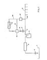
- FIGS. 1 to 4 Different versions of the device according to the invention can be found in the four representations according to FIGS. 1 to 4, in which the differently arranged elements are each identified identically. Differences only arise with regard to the branching and confluence points.
- a lubricating oil and cooling oil system is shown, in which lubricating oil is drawn in from an oil pan 1 by a lubricating oil feed pump 2, which is conveyed via a lubricating oil cooler 3 and a lubricating oil filter 4 to the supply points 5 of the internal combustion engine.
- a branch point 6 is provided in the lubricating oil and cooling oil system, to which a hydraulic pump 7 with a downstream throttle element 8 connects.
- a bypass 13 Parallel to a heating heat exchanger 12 is a bypass 13, which is controlled by a flow divider 14. It is possible to arrange the hydraulic pump 7 and the throttle element 8 in a first line loop 10 and the heating heat exchanger 12 and the flow divider 14 in a second line loop 15 (FIGS. 2, 4) or to connect them all in series in a common line loop 20 (FIG. 1, 3).
- the lubricating oil flowing out of the heating heat exchanger 12 or the bypass 13 can be filtered exclusively or additionally in an additional filter 17 (FIG. 1) within this line loop 15, 20.
- a check valve 18 can be provided in the line to the heating heat exchanger 12 to avoid leakage currents when the bypass 13 is open.
- the heating heat exchanger 12 can also be protected from excess pressure by a short-circuit valve 19 (FIG.
- the backflow from the heating heat exchanger 12 into the lubricating oil and cooling oil system takes place at a junction 16. Between the junction 16 and the junction 6 there is generally a backflow. 2 and 4, the heating system is represented by two line loops 10 and 15, the line loop 10, which contains the hydraulic pump 7 and the throttle element 8, ends at a hot oil return 9, the line loop 15, which contains the heat exchanger 12, takes in this case it begins at a hot oil branch 11, which is usually arranged behind the hot oil return 9 in the lubricating oil and cooling oil system.
- the line cross sections are to be designed such that, in particular when the heating device is divided into two line loops 10, 15, a sufficient flow over the heating heat exchanger 12 is ensured.
Landscapes
- Engineering & Computer Science (AREA)
- Physics & Mathematics (AREA)
- Thermal Sciences (AREA)
- Mechanical Engineering (AREA)
- Chemical & Material Sciences (AREA)
- Combustion & Propulsion (AREA)
- General Engineering & Computer Science (AREA)
- Lubrication Of Internal Combustion Engines (AREA)
- Harvester Elements (AREA)
- Yarns And Mechanical Finishing Of Yarns Or Ropes (AREA)
- Arc-Extinguishing Devices That Are Switches (AREA)
Claims (17)
le retour de l'échangeur de chaleur huile-air (12) étant relié au circuit d'huile de graissge ou de refroidissement en un point d'entrée (16) situé en amont des points d'alimentation en huile (5) du moteur thermique,
caractérisée par le fait qu'en aval de la pompe d'alimentation en huile de graissge (2) du circuit d'huile de graisage ou de refroidissement, vu dans le sens d'écoulement principal, le point de dérivation (6) d'une boucle de conduite (10 ou 20) soit situé en amont des points d'alimentation en huile (5) du moteur thermique, et que par son côté aspiration une pompe hydraulique (7) soit raccordée au point de dérivation (6) dans la boucle de conduite (10 ou 20) avec un élément d'étranglement (8) placé en aval, et que laboucle de conduite (10 ou 20) soit reliée au circuit d'huile de graissage ou de refroidissement par un point d'entrée (9 ou 16) en amont des points d'alimentation en huile (5) du moteur thermique.
caractérisé par le fait que le point de dérivation (6) vers la pompe hydraulique (7) vu dans le sens d'écoulement principal soit situé en amont du point d'entrée (16) de l'échangeur de chaleur huile-air (12) dans le circuit d'huile de graissage ou de refroidissement.
caractérisé par le fait que le point de dérivation (6) vers la pompe hydraulique (7) vu dans le sens d'écoulement principal, soit situé en aval du point d'entrée (16) de l'échangeur de chaleur air-huile (12) dans le circuit d'huile de graissage ou de refroidissement.
caractérisé par le fait que pompe hydraulique (7), élément d'étranglement (8) et échangeur de chaleur huile-air (12) soient placés l'un derrière l'autre entre le point de dérivation (6) et le point d'entrée (16) dans une seule boucle de conduite (20).
caractérisé par le fait que pompe hydraulique (7) et élément d'étranglement (8) soient disposés dans une première boucle de conduite (10) ramenée en amont du point d'entrée (16) sur un retour d'huile chaud (9) dans le circuit d'huile de graissage ou de refroidissement, et que le diviseur de débit (14) et l'échangeur de chaleur huile-air (12) soient disposés dans une seconde boucle de conduite (15), avec dérivation en amont du point d'entrée (16) dans une dérivation d'huile chaude (11) du circuit d'huile de graissge ou de refroidissement.
caractérisé par le fait qu'un filtre à huile de graissge (4) soit disposé dans le circuit d'huile de graissage ou de refroidissement immédiatement en amont du point de dérivation (6) et/ou immédiatement en aval du point d'entréee (16) et que le point de dérivation (6) et/ou le point d'entrée (16) soient situés dans des éléments de jonction entre le moteur thermique et le filtre à huile de graissage (4).
caractérisé par le fait qu'un refroidisseur d'huile de graissage (3) soit disposé en amont de la ou des boucles de conduites (10, 15, 20) pour pompe hydralique (7), élément d'étranglement (8), diviseur de débit (14) et échangeur de chaleur huile-air (12) dans le circuit d'huile de graissge ou de refroidissement et que le point de dérivation (6) et/ou le point d'entrée (16) et/ou le retour d'huile chaude (9) et/ou la dérivation d'huile chaude (11) soient situés dans des éléments de jonction entre le moteur et le refroidisseur d'huile de graissage (3).
caractérisé par le fait que le diviseur de débit (14) soit une vanne thermostatique.
caractérisé par le fait que le diviseur de débit (14) puisse être bloqué de sorte que le by-pass (13) soit en position ouverte.
caractérisé par le fait que le diviseur de débit (14) soit réglable dans le sens d'ouverture du by-pass (13) lorsque la pression amont descend au-dessous d'une valeur minimum fixée.
caractérisé par le fait que l'élément d'étranglement (8) soit un clapet réglable.
caractérisé par le fait que l'élément d'étranglement (8) présente un by-pass interne réglable.
caractérisé par le fait que l'élément d'étranglement (8) soit un limiteur de pression précontrôlé et que l'élément de précontrôle soit réglable en fonction de la température ou de la viscosité de l'huile moteur et/ou de la charge du moteur thermique ou de l'état de fonctionnement du véhicule.
caractérisé par le fait qu'il soit prévu un clapet de non-retour (18) en amont de l'échangeur huile-air (12) pour éviter des courants de fuite lorsque le by-pass (13) est ouvert.
caractérisé par le fait qu'il soit prévu une soupape de court-circuitage (19) en amont de l'échangeur de chaleur huile-air (12) à titre de sécurité de surpression lorsque le by-pass (13) est fermé.
caractérisé par le fait qu'il soit prévu un corps commun pour la pompe hydraulique (7), l'élément d'étranglement (8) et le diviseur de débit (14).
carctérisé par le fait que l'élément d'étranglement (8), le diviseur de débit (14) et le cas échéant le clapet de non-retour (18) et/ou la soupape de court-circuitage (19) soient disposés dans un même boîtier.
Priority Applications (1)
| Application Number | Priority Date | Filing Date | Title |
|---|---|---|---|
| AT82110513T ATE30543T1 (de) | 1981-12-24 | 1982-11-15 | Einrichtung zum beheizen einer bedienungskabine. |
Applications Claiming Priority (2)
| Application Number | Priority Date | Filing Date | Title |
|---|---|---|---|
| DE19813151472 DE3151472A1 (de) | 1981-12-24 | 1981-12-24 | Einrichtung zum beheizen einer bedienungskabine |
| DE3151472 | 1981-12-24 |
Publications (3)
| Publication Number | Publication Date |
|---|---|
| EP0082946A2 EP0082946A2 (fr) | 1983-07-06 |
| EP0082946A3 EP0082946A3 (en) | 1986-02-19 |
| EP0082946B1 true EP0082946B1 (fr) | 1987-11-04 |
Family
ID=6149785
Family Applications (1)
| Application Number | Title | Priority Date | Filing Date |
|---|---|---|---|
| EP82110513A Expired EP0082946B1 (fr) | 1981-12-24 | 1982-11-15 | Dispositif de chauffage d'une cabine de conduite |
Country Status (4)
| Country | Link |
|---|---|
| EP (1) | EP0082946B1 (fr) |
| AT (1) | ATE30543T1 (fr) |
| CA (1) | CA1185943A (fr) |
| DE (2) | DE3151472A1 (fr) |
Families Citing this family (2)
| Publication number | Priority date | Publication date | Assignee | Title |
|---|---|---|---|---|
| US4708095A (en) * | 1986-06-16 | 1987-11-24 | Deere & Company | Combined engine cooling and lube system |
| DE4344602A1 (de) * | 1993-12-24 | 1995-06-29 | Motoren Werke Mannheim Ag | Brennkraftmaschine mit einem Kühlmittelkreislauf |
Family Cites Families (13)
| Publication number | Priority date | Publication date | Assignee | Title |
|---|---|---|---|---|
| US2764147A (en) * | 1951-02-23 | 1956-09-25 | Northrop Aircraft Inc | Frictional heater for hydraulic system |
| US3259317A (en) * | 1961-12-26 | 1966-07-05 | Worthington Corp | Loading and drive systems for heat pumps |
| DE2351472C2 (de) * | 1973-10-13 | 1991-05-08 | Fa. J. Eberspächer, 7300 Esslingen | Heizeinrichtung für Fahrzeuge mit einem Motorkühlmittelkreislauf und einem der Innenraumbeheizung dienenden Kreislauf |
| FR2315666A1 (fr) * | 1975-06-27 | 1977-01-21 | Ppm Sa | Dispositif de chauffage utilisant la chaleur resultant du laminage d'un fluide sous pression |
| DE2623621C2 (de) * | 1976-05-26 | 1978-04-20 | Kloeckner-Humboldt-Deutz Ag, 5000 Koeln | Einrichtung zum Beheizen der Bedienungskabine einer Maschine |
| US4192456A (en) * | 1978-08-21 | 1980-03-11 | Harnischfeger Corporation | Heating system for machine operator's cab |
| DE2928999A1 (de) * | 1979-07-18 | 1981-02-12 | Kloeckner Humboldt Deutz Ag | Vorrichtung zur nutzung der erwaermten druckfluessigkeit der arbeitshydraulik eines kraftfahrzeugs |
| DE2932448A1 (de) * | 1979-08-10 | 1981-02-26 | Kloeckner Humboldt Deutz Ag | Einrichtung zum beheizen der bedienungskabine einer von einer brennkraftmaschine angetriebenen maschine |
| US4245593A (en) * | 1979-09-04 | 1981-01-20 | Kim Hotstart Manufacturing Co., Inc. | Liquid heating and circulating system |
| DE3001564A1 (de) * | 1980-01-17 | 1981-07-23 | Klöckner-Humboldt-Deutz AG, 5000 Köln | Einrichtung zum beheizen einer bedienungskabine |
| DE3005966A1 (de) * | 1980-02-16 | 1981-09-03 | Klöckner-Humboldt-Deutz AG, 5000 Köln | Einrichtung zum aufheizen von raumluft |
| FR2492327A1 (fr) * | 1980-10-18 | 1982-04-23 | Kloeckner Humboldt Deutz Ag | Installation de chauffage notamment pour une cabine de service, une cabine de vehicule ou analogue |
| DE3126534A1 (de) * | 1980-10-18 | 1982-05-27 | Klöckner-Humboldt-Deutz AG, 5000 Köln | Heizeinrichtung |
-
1981
- 1981-12-24 DE DE19813151472 patent/DE3151472A1/de not_active Withdrawn
-
1982
- 1982-11-15 EP EP82110513A patent/EP0082946B1/fr not_active Expired
- 1982-11-15 AT AT82110513T patent/ATE30543T1/de not_active IP Right Cessation
- 1982-11-15 DE DE8282110513T patent/DE3277574D1/de not_active Expired
- 1982-12-23 CA CA000418486A patent/CA1185943A/fr not_active Expired
Also Published As
| Publication number | Publication date |
|---|---|
| DE3151472A1 (de) | 1983-07-21 |
| EP0082946A2 (fr) | 1983-07-06 |
| EP0082946A3 (en) | 1986-02-19 |
| DE3277574D1 (en) | 1987-12-10 |
| CA1185943A (fr) | 1985-04-23 |
| ATE30543T1 (de) | 1987-11-15 |
Similar Documents
| Publication | Publication Date | Title |
|---|---|---|
| DE69600246T2 (de) | Temperaturregelungssystem für Schmieröl und Brennstoff in einem Turbostrahltriebwerk | |
| EP0067928B1 (fr) | Système de chauffage pour véhicules moteurs résultant du laminage de l'huile de graissage | |
| DE2631748A1 (de) | Oelkuehlungssystem fuer ein gasturbinentriebwerk | |
| EP0177025A2 (fr) | Système de refroidissement | |
| EP3516273B1 (fr) | Traitement de fluide hydraulique à alimentation en huile par système de pompe double | |
| EP0337124B1 (fr) | Transmission hydrostatique | |
| DE3047672A1 (de) | Kuehleinrichtung zur kuehlung einer brennkraftmaschine und der ladeluft | |
| DE112011105266T5 (de) | Fluidsteuersystem | |
| EP0376150B1 (fr) | Moteur à combustion interne avec deux circuits à liquide hydraulique | |
| CH654257A5 (de) | Heizeinrichtung an einer arbeitsmaschine zur heizung einer bedienungskabine oder eines fahrerhauses. | |
| DE2623621B1 (de) | Einrichtung zum beheizen der bedienungskabine einer maschine | |
| EP0032676A2 (fr) | Installation de chauffage pour cabine de conduite | |
| EP0717175B1 (fr) | Agencement pour le refoulement et le refroidissement du lubrifiant des moteurs à combustion interne | |
| DE4342784A1 (de) | Hydraulikkreis | |
| DE2249818A1 (de) | Kuehlsystem fuer das in verbrennungskraftmaschinen umlaufende schmieroel | |
| DE4121379A1 (de) | Verfahren zum betreiben einer kuehleinrichtung fuer eine brennkraftmaschine und kuehleinrichtung zur durchfuehrung des verfahrens | |
| EP0082946B1 (fr) | Dispositif de chauffage d'une cabine de conduite | |
| DE3622378A1 (de) | Kuehlfluessigkeitssystem fuer eine brennkraftmaschine | |
| DE19823603A1 (de) | Vorrichtung zum Steuern der Kühlmitteltemperatur eines Verbrennungsmotors eines Fahrzeuges | |
| EP0262598B1 (fr) | Moteur à combustion interne | |
| DE102022131628B3 (de) | Vorrichtung für ein hydraulisches System, hydraulisches System, Antriebsmodul eines Kraftfahrzeugs | |
| DE4015374C2 (de) | Hydrostatisch-mechanischer Antrieb von Nebenaggregaten | |
| DE102006013867A1 (de) | Verfahren und Vorrichtung zur Öltemperierung bei Kraftfahrzeugen mit Verbrennungskraftmaschinen | |
| DE1216014B (de) | Umlaufsystem zur Schmierung und Kolbenkuehlung von Brennkraftmaschinen | |
| DE102010009290B4 (de) | Kühlmittelkreislauf für eine Brennkraftmaschine mit Abgasrückführung |
Legal Events
| Date | Code | Title | Description |
|---|---|---|---|
| PUAI | Public reference made under article 153(3) epc to a published international application that has entered the european phase |
Free format text: ORIGINAL CODE: 0009012 |
|
| AK | Designated contracting states |
Designated state(s): AT CH DE FR GB IT LI NL SE |
|
| PUAL | Search report despatched |
Free format text: ORIGINAL CODE: 0009013 |
|
| AK | Designated contracting states |
Designated state(s): AT CH DE FR GB IT LI NL SE |
|
| 17P | Request for examination filed |
Effective date: 19860124 |
|
| 17Q | First examination report despatched |
Effective date: 19860807 |
|
| GRAA | (expected) grant |
Free format text: ORIGINAL CODE: 0009210 |
|
| AK | Designated contracting states |
Kind code of ref document: B1 Designated state(s): AT CH DE FR GB IT LI NL SE |
|
| PG25 | Lapsed in a contracting state [announced via postgrant information from national office to epo] |
Ref country code: NL Effective date: 19871104 Ref country code: IT Free format text: LAPSE BECAUSE OF FAILURE TO SUBMIT A TRANSLATION OF THE DESCRIPTION OR TO PAY THE FEE WITHIN THE PRESCRIBED TIME-LIMIT;WARNING: LAPSES OF ITALIAN PATENTS WITH EFFECTIVE DATE BEFORE 2007 MAY HAVE OCCURRED AT ANY TIME BEFORE 2007. THE CORRECT EFFECTIVE DATE MAY BE DIFFERENT FROM THE ONE RECORDED. Effective date: 19871104 Ref country code: FR Free format text: THE PATENT HAS BEEN ANNULLED BY A DECISION OF A NATIONAL AUTHORITY Effective date: 19871104 |
|
| REF | Corresponds to: |
Ref document number: 30543 Country of ref document: AT Date of ref document: 19871115 Kind code of ref document: T |
|
| PG25 | Lapsed in a contracting state [announced via postgrant information from national office to epo] |
Ref country code: SE Effective date: 19871130 |
|
| REF | Corresponds to: |
Ref document number: 3277574 Country of ref document: DE Date of ref document: 19871210 |
|
| GBT | Gb: translation of ep patent filed (gb section 77(6)(a)/1977) | ||
| EN | Fr: translation not filed | ||
| NLV1 | Nl: lapsed or annulled due to failure to fulfill the requirements of art. 29p and 29m of the patents act | ||
| PLBE | No opposition filed within time limit |
Free format text: ORIGINAL CODE: 0009261 |
|
| STAA | Information on the status of an ep patent application or granted ep patent |
Free format text: STATUS: NO OPPOSITION FILED WITHIN TIME LIMIT |
|
| 26N | No opposition filed | ||
| PGFP | Annual fee paid to national office [announced via postgrant information from national office to epo] |
Ref country code: AT Payment date: 19891009 Year of fee payment: 8 |
|
| PGFP | Annual fee paid to national office [announced via postgrant information from national office to epo] |
Ref country code: CH Payment date: 19891016 Year of fee payment: 8 |
|
| PGFP | Annual fee paid to national office [announced via postgrant information from national office to epo] |
Ref country code: GB Payment date: 19891031 Year of fee payment: 8 |
|
| PG25 | Lapsed in a contracting state [announced via postgrant information from national office to epo] |
Ref country code: DE Effective date: 19900801 |
|
| PG25 | Lapsed in a contracting state [announced via postgrant information from national office to epo] |
Ref country code: GB Effective date: 19901115 Ref country code: AT Effective date: 19901115 |
|
| PG25 | Lapsed in a contracting state [announced via postgrant information from national office to epo] |
Ref country code: LI Effective date: 19901130 Ref country code: CH Effective date: 19901130 |
|
| GBPC | Gb: european patent ceased through non-payment of renewal fee | ||
| REG | Reference to a national code |
Ref country code: CH Ref legal event code: PL |