EP0337124B1 - Transmission hydrostatique - Google Patents
Transmission hydrostatique Download PDFInfo
- Publication number
- EP0337124B1 EP0337124B1 EP89104312A EP89104312A EP0337124B1 EP 0337124 B1 EP0337124 B1 EP 0337124B1 EP 89104312 A EP89104312 A EP 89104312A EP 89104312 A EP89104312 A EP 89104312A EP 0337124 B1 EP0337124 B1 EP 0337124B1
- Authority
- EP
- European Patent Office
- Prior art keywords
- line
- pressure
- valve
- hydrostatic transmission
- hydraulic motor
- Prior art date
- Legal status (The legal status is an assumption and is not a legal conclusion. Google has not performed a legal analysis and makes no representation as to the accuracy of the status listed.)
- Expired - Lifetime
Links
- 230000005540 biological transmission Effects 0.000 title claims description 38
- 230000002706 hydrostatic effect Effects 0.000 title claims description 27
- 239000012530 fluid Substances 0.000 description 12
- 238000011144 upstream manufacturing Methods 0.000 description 6
- XLYOFNOQVPJJNP-UHFFFAOYSA-N water Substances O XLYOFNOQVPJJNP-UHFFFAOYSA-N 0.000 description 6
- 230000000694 effects Effects 0.000 description 4
- 230000006835 compression Effects 0.000 description 3
- 238000007906 compression Methods 0.000 description 3
- 238000010438 heat treatment Methods 0.000 description 2
- 238000000034 method Methods 0.000 description 2
- 230000003247 decreasing effect Effects 0.000 description 1
- 238000006073 displacement reaction Methods 0.000 description 1
- 230000008014 freezing Effects 0.000 description 1
- 238000007710 freezing Methods 0.000 description 1
- 230000001771 impaired effect Effects 0.000 description 1
- 238000004519 manufacturing process Methods 0.000 description 1
- 239000002184 metal Substances 0.000 description 1
- 238000012986 modification Methods 0.000 description 1
- 230000004048 modification Effects 0.000 description 1
- 230000007704 transition Effects 0.000 description 1
Images

Classifications
-
- F—MECHANICAL ENGINEERING; LIGHTING; HEATING; WEAPONS; BLASTING
- F16—ENGINEERING ELEMENTS AND UNITS; GENERAL MEASURES FOR PRODUCING AND MAINTAINING EFFECTIVE FUNCTIONING OF MACHINES OR INSTALLATIONS; THERMAL INSULATION IN GENERAL
- F16H—GEARING
- F16H61/00—Control functions within control units of change-speed- or reversing-gearings for conveying rotary motion ; Control of exclusively fluid gearing, friction gearing, gearings with endless flexible members or other particular types of gearing
- F16H61/38—Control of exclusively fluid gearing
- F16H61/40—Control of exclusively fluid gearing hydrostatic
- F16H61/4165—Control of cooling or lubricating
-
- F—MECHANICAL ENGINEERING; LIGHTING; HEATING; WEAPONS; BLASTING
- F15—FLUID-PRESSURE ACTUATORS; HYDRAULICS OR PNEUMATICS IN GENERAL
- F15B—SYSTEMS ACTING BY MEANS OF FLUIDS IN GENERAL; FLUID-PRESSURE ACTUATORS, e.g. SERVOMOTORS; DETAILS OF FLUID-PRESSURE SYSTEMS, NOT OTHERWISE PROVIDED FOR
- F15B11/00—Servomotor systems without provision for follow-up action; Circuits therefor
- F15B11/02—Systems essentially incorporating special features for controlling the speed or actuating force of an output member
- F15B11/04—Systems essentially incorporating special features for controlling the speed or actuating force of an output member for controlling the speed
- F15B11/044—Systems essentially incorporating special features for controlling the speed or actuating force of an output member for controlling the speed by means in the return line, i.e. "meter out"
- F15B11/0445—Systems essentially incorporating special features for controlling the speed or actuating force of an output member for controlling the speed by means in the return line, i.e. "meter out" with counterbalance valves, e.g. to prevent overrunning or for braking
-
- F—MECHANICAL ENGINEERING; LIGHTING; HEATING; WEAPONS; BLASTING
- F16—ENGINEERING ELEMENTS AND UNITS; GENERAL MEASURES FOR PRODUCING AND MAINTAINING EFFECTIVE FUNCTIONING OF MACHINES OR INSTALLATIONS; THERMAL INSULATION IN GENERAL
- F16H—GEARING
- F16H61/00—Control functions within control units of change-speed- or reversing-gearings for conveying rotary motion ; Control of exclusively fluid gearing, friction gearing, gearings with endless flexible members or other particular types of gearing
- F16H61/38—Control of exclusively fluid gearing
- F16H61/40—Control of exclusively fluid gearing hydrostatic
- F16H61/4035—Control of circuit flow
-
- F—MECHANICAL ENGINEERING; LIGHTING; HEATING; WEAPONS; BLASTING
- F16—ENGINEERING ELEMENTS AND UNITS; GENERAL MEASURES FOR PRODUCING AND MAINTAINING EFFECTIVE FUNCTIONING OF MACHINES OR INSTALLATIONS; THERMAL INSULATION IN GENERAL
- F16H—GEARING
- F16H61/00—Control functions within control units of change-speed- or reversing-gearings for conveying rotary motion ; Control of exclusively fluid gearing, friction gearing, gearings with endless flexible members or other particular types of gearing
- F16H61/38—Control of exclusively fluid gearing
- F16H61/40—Control of exclusively fluid gearing hydrostatic
- F16H61/4078—Fluid exchange between hydrostatic circuits and external sources or consumers
- F16H61/4096—Fluid exchange between hydrostatic circuits and external sources or consumers with pressure accumulators
-
- F—MECHANICAL ENGINEERING; LIGHTING; HEATING; WEAPONS; BLASTING
- F16—ENGINEERING ELEMENTS AND UNITS; GENERAL MEASURES FOR PRODUCING AND MAINTAINING EFFECTIVE FUNCTIONING OF MACHINES OR INSTALLATIONS; THERMAL INSULATION IN GENERAL
- F16H—GEARING
- F16H61/00—Control functions within control units of change-speed- or reversing-gearings for conveying rotary motion ; Control of exclusively fluid gearing, friction gearing, gearings with endless flexible members or other particular types of gearing
- F16H61/38—Control of exclusively fluid gearing
- F16H61/40—Control of exclusively fluid gearing hydrostatic
- F16H61/4174—Control of venting, e.g. removing trapped air
-
- F—MECHANICAL ENGINEERING; LIGHTING; HEATING; WEAPONS; BLASTING
- F16—ENGINEERING ELEMENTS AND UNITS; GENERAL MEASURES FOR PRODUCING AND MAINTAINING EFFECTIVE FUNCTIONING OF MACHINES OR INSTALLATIONS; THERMAL INSULATION IN GENERAL
- F16H—GEARING
- F16H61/00—Control functions within control units of change-speed- or reversing-gearings for conveying rotary motion ; Control of exclusively fluid gearing, friction gearing, gearings with endless flexible members or other particular types of gearing
- F16H61/38—Control of exclusively fluid gearing
- F16H61/40—Control of exclusively fluid gearing hydrostatic
- F16H61/46—Automatic regulation in accordance with output requirements
- F16H61/461—Automatic regulation in accordance with output requirements not involving a variation of the output capacity of the main pumps or motors
-
- F—MECHANICAL ENGINEERING; LIGHTING; HEATING; WEAPONS; BLASTING
- F15—FLUID-PRESSURE ACTUATORS; HYDRAULICS OR PNEUMATICS IN GENERAL
- F15B—SYSTEMS ACTING BY MEANS OF FLUIDS IN GENERAL; FLUID-PRESSURE ACTUATORS, e.g. SERVOMOTORS; DETAILS OF FLUID-PRESSURE SYSTEMS, NOT OTHERWISE PROVIDED FOR
- F15B2211/00—Circuits for servomotor systems
- F15B2211/40—Flow control
- F15B2211/405—Flow control characterised by the type of flow control means or valve
- F15B2211/40507—Flow control characterised by the type of flow control means or valve with constant throttles or orifices
-
- F—MECHANICAL ENGINEERING; LIGHTING; HEATING; WEAPONS; BLASTING
- F15—FLUID-PRESSURE ACTUATORS; HYDRAULICS OR PNEUMATICS IN GENERAL
- F15B—SYSTEMS ACTING BY MEANS OF FLUIDS IN GENERAL; FLUID-PRESSURE ACTUATORS, e.g. SERVOMOTORS; DETAILS OF FLUID-PRESSURE SYSTEMS, NOT OTHERWISE PROVIDED FOR
- F15B2211/00—Circuits for servomotor systems
- F15B2211/40—Flow control
- F15B2211/405—Flow control characterised by the type of flow control means or valve
- F15B2211/40553—Flow control characterised by the type of flow control means or valve with pressure compensating valves
- F15B2211/40561—Flow control characterised by the type of flow control means or valve with pressure compensating valves the pressure compensating valve arranged upstream of the flow control means
-
- F—MECHANICAL ENGINEERING; LIGHTING; HEATING; WEAPONS; BLASTING
- F15—FLUID-PRESSURE ACTUATORS; HYDRAULICS OR PNEUMATICS IN GENERAL
- F15B—SYSTEMS ACTING BY MEANS OF FLUIDS IN GENERAL; FLUID-PRESSURE ACTUATORS, e.g. SERVOMOTORS; DETAILS OF FLUID-PRESSURE SYSTEMS, NOT OTHERWISE PROVIDED FOR
- F15B2211/00—Circuits for servomotor systems
- F15B2211/40—Flow control
- F15B2211/405—Flow control characterised by the type of flow control means or valve
- F15B2211/40553—Flow control characterised by the type of flow control means or valve with pressure compensating valves
- F15B2211/40569—Flow control characterised by the type of flow control means or valve with pressure compensating valves the pressure compensating valve arranged downstream of the flow control means
-
- F—MECHANICAL ENGINEERING; LIGHTING; HEATING; WEAPONS; BLASTING
- F15—FLUID-PRESSURE ACTUATORS; HYDRAULICS OR PNEUMATICS IN GENERAL
- F15B—SYSTEMS ACTING BY MEANS OF FLUIDS IN GENERAL; FLUID-PRESSURE ACTUATORS, e.g. SERVOMOTORS; DETAILS OF FLUID-PRESSURE SYSTEMS, NOT OTHERWISE PROVIDED FOR
- F15B2211/00—Circuits for servomotor systems
- F15B2211/40—Flow control
- F15B2211/455—Control of flow in the feed line, i.e. meter-in control
-
- F—MECHANICAL ENGINEERING; LIGHTING; HEATING; WEAPONS; BLASTING
- F15—FLUID-PRESSURE ACTUATORS; HYDRAULICS OR PNEUMATICS IN GENERAL
- F15B—SYSTEMS ACTING BY MEANS OF FLUIDS IN GENERAL; FLUID-PRESSURE ACTUATORS, e.g. SERVOMOTORS; DETAILS OF FLUID-PRESSURE SYSTEMS, NOT OTHERWISE PROVIDED FOR
- F15B2211/00—Circuits for servomotor systems
- F15B2211/40—Flow control
- F15B2211/46—Control of flow in the return line, i.e. meter-out control
-
- F—MECHANICAL ENGINEERING; LIGHTING; HEATING; WEAPONS; BLASTING
- F15—FLUID-PRESSURE ACTUATORS; HYDRAULICS OR PNEUMATICS IN GENERAL
- F15B—SYSTEMS ACTING BY MEANS OF FLUIDS IN GENERAL; FLUID-PRESSURE ACTUATORS, e.g. SERVOMOTORS; DETAILS OF FLUID-PRESSURE SYSTEMS, NOT OTHERWISE PROVIDED FOR
- F15B2211/00—Circuits for servomotor systems
- F15B2211/60—Circuit components or control therefor
- F15B2211/61—Secondary circuits
- F15B2211/613—Feeding circuits
-
- F—MECHANICAL ENGINEERING; LIGHTING; HEATING; WEAPONS; BLASTING
- F15—FLUID-PRESSURE ACTUATORS; HYDRAULICS OR PNEUMATICS IN GENERAL
- F15B—SYSTEMS ACTING BY MEANS OF FLUIDS IN GENERAL; FLUID-PRESSURE ACTUATORS, e.g. SERVOMOTORS; DETAILS OF FLUID-PRESSURE SYSTEMS, NOT OTHERWISE PROVIDED FOR
- F15B2211/00—Circuits for servomotor systems
- F15B2211/70—Output members, e.g. hydraulic motors or cylinders or control therefor
- F15B2211/705—Output members, e.g. hydraulic motors or cylinders or control therefor characterised by the type of output members or actuators
- F15B2211/7058—Rotary output members
-
- F—MECHANICAL ENGINEERING; LIGHTING; HEATING; WEAPONS; BLASTING
- F16—ENGINEERING ELEMENTS AND UNITS; GENERAL MEASURES FOR PRODUCING AND MAINTAINING EFFECTIVE FUNCTIONING OF MACHINES OR INSTALLATIONS; THERMAL INSULATION IN GENERAL
- F16H—GEARING
- F16H61/00—Control functions within control units of change-speed- or reversing-gearings for conveying rotary motion ; Control of exclusively fluid gearing, friction gearing, gearings with endless flexible members or other particular types of gearing
- F16H61/38—Control of exclusively fluid gearing
- F16H61/40—Control of exclusively fluid gearing hydrostatic
- F16H61/4043—Control of a bypass valve
- F16H61/4052—Control of a bypass valve by using a variable restriction, e.g. an orifice valve
Definitions
- the invention relates to a hydrostatic transmission according to the preamble of claim 1. Such a transmission is generally known.
- the Max. permissible head is very limited.
- the viscosity values of the operating fluid must be selected accordingly in relation to the operating and ambient temperatures that occur. At extremely low temperatures and with high line resistances, this is not sufficient in most cases, and the operating fluid must be preheated accordingly, especially during start-up operations, before operation at nominal power is possible. For example, it would be possible to heat the operating fluid by means of external heating before starting.
- a bypass circuit has also already been proposed, consisting of a valve chain arranged in a bypass connecting the high-pressure line and the low-pressure line with a pressure relief valve, which is set such that, taking into account the max. permissible return pressure circulates only a fraction of the normal flow in the main line.
- the circuit can be heated up with the heat loss at the pressure relief valve.
- the invention has for its object to design a hydrostatic transmission of the type mentioned in such a way that the housing of the hydraulic motor is released from impermissibly high pressures of the main line.
- the circuit is throttled at a point in the flow direction upstream of the line connection for the leak oil line of the hydraulic motor when the pressure in the main line, which can affect the leak oil line and the motor housing through the low pressure line, exceeds a predetermined value. It is possible within the scope of the invention to adjust the flow cross section of the valve depending on either the pressure or the temperature in the main line. The latter requirement also leads to an advantageous solution because the viscosity of the hydraulic fluid increases at low temperatures, which likewise leads to the problems described at the outset and is often the cause of these problems.
- the valve can be controlled electrically, hydraulically or mechanically. As soon as the pressure drops or the temperature of the hydraulic medium rises, the valve is preferably opened continuously or its flow cross section is continuously increased. In normal operation, i.e. under normal pressure conditions or at normal outside temperature or after the gearbox has warmed up, the throttling can be completely removed.
- valve according to the invention there can be no harmful high pressure in the area of the line connection of the leak oil line, since the valve according to the invention throttles or stops the supply of the hydraulic fluid to the line connection and a harmful high pressure cannot have any effect.
- the valve can be arranged according to claims 2 to 4 upstream of the line connection for the leak oil line and both in the high pressure line and in the low pressure line. an arrangement of the valve in the vicinity of the hydraulic motor is recommended for reasons of a simple and functionally reliable design.
- the embodiment according to claim 5 contributes to further simplification of the configuration according to the invention, which results in an automatic adjustment of the valve, in particular without additional control signals from the area of the pump, so that there are also no long control lines between the area in which the pump is arranged and the valve are required.
- valve body of the valve is acted upon as a function of the pressure drop of a preferably constant throttle, which can be arranged both in the high-pressure line and in the low-pressure line and both upstream and downstream of the valve. It is essential that the throttle is arranged in the flow direction upstream of the line connection of the leak oil line, so that a damagingly high pressure in the low pressure line cannot affect the leak oil channel and thus not the housing of the hydraulic motor.
- the design according to claim 11 is advantageous for design reasons and handling reasons.
- a circulation of the hydraulic fluid in the main line is ensured while maintaining a certain working pressure if the main line behind the bypass is blocked or the flow is impaired.
- heating occurs which can advantageously be used to warm up the hydraulic fluid in the event of cold start difficulties.
- the configuration according to the invention is suitable both for an open circuit and preferably for a closed circuit.
- the configuration according to the invention is particularly suitable for those applications in which the aforementioned transmission parts are connected to one another only by the high-pressure line and the low-pressure line, in the form of flexible lines such as hoses .
- the transmission part containing the hydraulic motor can be displaced independently of the transmission part containing the pump.
- a preferred application for a hydrostatic transmission designed according to the invention is shipbuilding, since even with a large distance between the pump and the hydraulic motor, a practical arrangement and handling of the transmission part containing the hydraulic motor is possible.
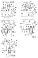
- the hydrostatic transmission generally designated 1 in FIG. 1, consists in the usual manner of a pump 2 and a hydraulic motor 3 in the form of axial piston machines which are inserted into a main circuit, generally designated 4, whose flow direction (arrow) depends on the pump 2 line section leading to the hydraulic motor 3 is the high-pressure line 5 and line section leading from the hydraulic motor 3 to the hydraulic pump 2 is the low-pressure line 6.
- the part of the transmission containing the pump 2 is designated by 7 and the part of the transmission containing the hydraulic motor 3 is designated by 8.
- the gear parts 7, 8 preferably form two parts that are independent of one another in terms of position and are connected only by the high-pressure line 5 and the low-pressure line 6 in the form of flexible hydraulic lines made of plastic or metal.
- the pump 2 and the hydraulic motor 3 are formed by constant displacement axial piston machines which are set up for operation in only one direction of rotation.
- the pump 2 is driven by a drive motor, not shown, by means of an input shaft 9.
- An output shaft 11 is assigned to the hydraulic motor 3, with which a consumer, such as a working machine or a running gear, can be driven.
- the closed circuit of the hydrostatic transmission 1 is connected in the area of the low pressure line 6 near the pump 2 to a hydraulic accumulator 14, by means of which the system is preloaded.
- the accumulator 14 is charged via a filling device with a pump 16 sucking from an oil tank 15 and a check valve 17 closing towards the pump 16, which are arranged in a hydraulic line section 18 and are also connected to the low pressure line 6 at 13.
- a heat exchanger 19 is arranged in the high-pressure line 5, by means of which the heat loss generated during operation is dissipated in a manner not shown.
- a bypass line 21, in which a pressure relief valve 22 is arranged extends between the high pressure line 5 and the low pressure line 6.
- the hydraulic motor 3 and the pump 2 are connected to the low-pressure line 6 by leak oil lines 23, 24, which ensures that the leak oil is discharged into the low-pressure line 6.
- valve spool 26 In order to prevent a high and therefore harmful, build-up in the low pressure line 6 due to the leakage oil line 23 pressure from the inside on the housing of the hydraulic motor 3 at low temperatures, is in the high pressure line 5 in the vicinity of the hydraulic motor 3 Throttle valve 25 is arranged, the valve spool 26 can be acted upon on both ends by a hydraulic cylinder 27, 28, which are assigned to the housing of the throttle valve 25. The valve spool 26 is acted upon as a function of the differential pressure upstream and downstream of a constant throttle 29 which is arranged in the low-pressure line 6 in the flow direction (arrow 30) in front of the line connection 31, through which the leak oil line 23 is connected to the low-pressure line 6.
- Constant throttle 29 emanate from the low pressure line 6 lines 32, 33, of which the line 32, which carries the higher pressure of the differential pressure, is connected to the hydraulic cylinder 27 and the line 33, which carries the lower pressure of the differential pressure, is connected to the hydraulic cylinder 28 .
- the line 33 is connected to the leak oil line 23 at 34, but the pressure existing behind the constant throttle 29 acts in both the leak oil line 23 and the line 33.
- a compression spring 35 is assigned to the hydraulic cylinder 28, the spring force of which is adjustable. The higher pressure of the differential pressure thus acts against the compression spring 35.
- the valve slide 26 can be adjusted inversely proportional to the pressure present in the area of the constant throttle 29, ie it can be continuously adjusted between a maximum and minimum position.
- the above-described hydrostatic transmission 1 is preferably intended for driving a fire water pump (not shown) for a ship, which is driven by the hydraulic motor 3 and preferably with the hydraulic motor 3, the throttle valve 25 and the constant throttle 29, a structural unit, in particular in the form of a block, forms. Due to the design of the high-pressure line 5 and the low-pressure line 6 as flexible lines, preferably plastic lines, the unit identified by 38 can be thrown overboard in a simple manner in order to bring the fire water pump into contact with the water in which the ship is located.
- the driven pump 2 conveys the hydraulic fluid present in the main line 4 in the direction of the arrow 30, as a result of which the hydraulic motor 3 is driven. If, for example, due to the cold and the resulting high viscosity in the low-pressure line 6, a pressure increase to a predeterminable value occurs, the valve slide 26 is automatically hydraulically shifted into a throttle position, so that in the present exemplary embodiment the delivery quantity reaching the hydraulic motor 3 is throttled so that the predeterminable pressure in the low-pressure line 6 is not exceeded.
- the transition between the functional positions of the valve spool 26 takes place approximately steadily with regard to the throttle effect, ie the throttle valve 25 is closed with increasing pressure in the low-pressure line 6 and opened with decreasing pressure.
- the pressure difference between the control lines 32, 33 corresponds to the pressure drop across the constant throttle 29, which occurs as a function of the flow rate and the viscosity of the operating fluid.
- the pressure drop at the constant throttle 29 thus behaves in proportion to the pressure drop in the entire low pressure line 6 and serves as a control variable for the position of the valve spool 26.
- the max. Throttling effect of valve spool 26 is defined by the max. permissible operating viscosity and that flow rate that, under the given system pressure - determined by the pressure relief valve 22 - in the low pressure line 6 the max. permissible pressure. As long as the valve slide 26 has not switched to free passage, the transmission is in the cold start area. The energy not absorbed by the hydraulic motor 3 is completely converted into heat at the throttle point of the pressure relief valve 22 and the useful energy flowing to the hydraulic motor 3 is partially converted into heat at the throttle point of the throttle valve 25 and thus serves to rapidly heat up the circuit.
- the full input power is always automatically taken up by the hydraulic pump 2, because the throttle valve 25 does not allow the entire flow to pass, and so a partial flow has to flow through the pressure relief valve 22 under the highest system pressure.
- This system pressure determines the size of the power consumption.
- the torque simultaneously output on the hydraulic motor 3 does not determine the operating pressure of the hydraulic pump 2 in this phase.
- the constant throttle 29 and the line connections 34, 36 for the control lines 32, 33 are located in the high-pressure line 5, specifically in front of the throttle valve 25.
- the constant throttle 29 is located and the line connections 31, 34 in the exemplary embodiment according to FIG. 3 likewise in the high-pressure line 5, but in the flow direction behind the throttle valve 25, ie between the latter and the hydraulic motor 3.
- the throttled delivery rate is supplied to the hydraulic motor 3.
- the throttle valve 25 is located in the low-pressure line 6, in the flow direction upstream of the line connection 31 for the leak oil line 23, the constant throttle 29 and the line connections 34, 36 for the control lines 32, 33 in the flow direction before the throttle valve 25, ie between the latter and the hydraulic motor 3 (Fig. 4) in the flow direction behind the throttle valve 25, i.e. can be arranged between the latter and the line connection 31 for the leak oil line 23 (FIG. 5) or in the high pressure line 5 (FIG. 6).
- valve slide 26 only between two functional positions (open, closed or throttled).
- the amount of flow is thus throttled before the line connection 31 for the leak oil line 23, so that the low pressure line 6, i.e. at least in the area of the line connection 31 for the leak oil line 23, no harmful pressure can build up.
Landscapes
- Engineering & Computer Science (AREA)
- General Engineering & Computer Science (AREA)
- Mechanical Engineering (AREA)
- Physics & Mathematics (AREA)
- Fluid Mechanics (AREA)
- Fluid-Pressure Circuits (AREA)
- Control Of Fluid Gearings (AREA)
- Motor Power Transmission Devices (AREA)
Claims (14)
- Transmission hydrostatique (1), avec une pompe (2) et un moteur hydraulique (3), disposés dans une conduite principale (4) présentant une conduite haute pression et une conduite basse pression, une conduite d'huile de fuite (23) du moteur hydraulique (3) étant raccordée à la conduite basse pression (6) de la conduite principale (4), caractérisée en ce qu'une soupape (25) à section transversale d'écoulement réglable, présentant un corps de soupape (26), est disposée en amont du raccordement de conduite (31) de la conduite d'huile de fuite (23), dans la direction de l'écoulement (flèche 30), et diminue la section transversale d'écoulement lorsque la pression augmente ou qu'une basse température règne dans la conduite principale (4).
- Transmission hydrostatique selon la revendication 1, caractérisée en ce que la soupape (25) est disposée à proximité du moteur hydraulique (3).
- Transmission hydrostatique selon l'une des revendications 1 à 2, caractérisée en ce que la soupape (25) est disposée dans la conduite haute pression (5).
- Transmission hydrostatique selon l'une des revendications 1 à 2, caractérisée en ce que la soupape (25) est disposée dans la conduite basse pression (6).
- Transmission hydrostatique selon l'une des revendications 1 à 4, caractérisée en ce que le corps de soupape (26) de la soupape (25) peut être sollicité par la pression dans la direction d'écoulement, en amont d'un étranglement (29) placé dans la conduite principale (4) et disposé de préférence à proximité du moteur hydraulique (3).
- Transmission hydrostatique selon la revendication 5, caractérisée en ce que le corps de soupape (26) peut être sollicité sur son autre côté par la pression dans la direction d'écoulement (30), en aval de l'étranglement (29).
- Transmission hydrostatique selon la revendication 5 ou 6, caractérisée en ce que le corps de soupape (26) peut être sollicité par la pression régnant en amont de l'étranglement (29) et à l'encontre de la force d'un ressort.
- Transmission hydrostatique selon l'une des revendications 5 à 7, caractérisée en ce que l'étranglement (29) est disposé dans la conduite basse pression (6), entre le moteur hydraulique (3) et le raccordement de conduite (31) destiné à la conduite d'huile de fuite (23) (figure 1).
- Transmission hydrostatique selon l'une des revendications 5 à 7, caractérisée en ce que l'étranglement (29) est disposé dans la conduite haute pression (5) (figure 6).
- Transmission hydrostatique selon l'une des revendications 5 à 9, caractérisée en ce que l'étranglement (29) est disposé en amont ou en aval de la soupape (26), dans la direction d'écoulement (30) (figures 2, 4 et 6 ou figure 1, 3 et figure 5).
- Transmission hydrostatique selon l'une des revendications 1 à 10, caractérisée en ce que la soupape (25), l'étranglement (29) et/ou les raccordements de conduite (34, 36) sont disposés dans un ensemble de construction (38) ou un élément de construction contenant le moteur hydraulique (3).
- Transmission hydrostatique selon l'une des revendications 1 à 11, caractérisée en ce qu'une conduite de dérivation (21) est prévue, de préférence à proximité de la pompe (2), entra la conduite haute pression (5) et la conduite basse pression (6), dans laquelle est disposée une soupape de surpression (22).
- Transmission hydrostatique salon l'une des revendications 1 à 12, caractérisée en ce que la pompe (2) est raccordée à la conduite basse pression (6) par l'intermédiaire d'une conduite d'huile de fuite (24).
- Transmission hydrostatique selon l'une des revendications 1 à 13, caractérisée en ce que la transmission hydrostatique est an circuit fermé.
Applications Claiming Priority (2)
| Application Number | Priority Date | Filing Date | Title |
|---|---|---|---|
| DE3812300A DE3812300C1 (fr) | 1988-04-13 | 1988-04-13 | |
| DE3812300 | 1988-04-13 |
Publications (3)
| Publication Number | Publication Date |
|---|---|
| EP0337124A2 EP0337124A2 (fr) | 1989-10-18 |
| EP0337124A3 EP0337124A3 (fr) | 1991-06-26 |
| EP0337124B1 true EP0337124B1 (fr) | 1994-05-18 |
Family
ID=6351897
Family Applications (1)
| Application Number | Title | Priority Date | Filing Date |
|---|---|---|---|
| EP89104312A Expired - Lifetime EP0337124B1 (fr) | 1988-04-13 | 1989-03-10 | Transmission hydrostatique |
Country Status (3)
| Country | Link |
|---|---|
| US (1) | US5048295A (fr) |
| EP (1) | EP0337124B1 (fr) |
| DE (2) | DE3812300C1 (fr) |
Cited By (1)
| Publication number | Priority date | Publication date | Assignee | Title |
|---|---|---|---|---|
| DE102014011073B3 (de) * | 2014-07-30 | 2015-11-12 | Danfoss Power Solutions Gmbh & Co. Ohg | 1Motordrehzahlbegrenzungsvorrichtung |
Families Citing this family (19)
| Publication number | Priority date | Publication date | Assignee | Title |
|---|---|---|---|---|
| US5203172A (en) * | 1990-05-17 | 1993-04-20 | Simpson Alvin B | Electromagnetically powered hydraulic engine |
| US5170692A (en) * | 1991-11-04 | 1992-12-15 | Vickers, Incorporated | Hydraulic control system |
| US5235810A (en) * | 1992-09-28 | 1993-08-17 | Tecumseh Products Company | Conduit valve providing wide neutral in a hydrostatic transmission |
| US5355675A (en) * | 1993-08-31 | 1994-10-18 | Western Atlas International, Inc. | Stabilized speed-control system for a hydrostatic transmission |
| US5533333A (en) * | 1994-04-29 | 1996-07-09 | Atlantic Richfield Company | Method and regulator for regulating the air pressure of a pressurized vessel |
| US5467596A (en) * | 1994-11-09 | 1995-11-21 | Applied Power Inc. | Unitary electro-hydraulic rotary actuator for automotive convertible top |
| US6338247B1 (en) * | 1998-11-20 | 2002-01-15 | Sauer-Danfoss Inc. | System for controlling a hydraulic vehicle drive |
| US6336325B1 (en) | 1999-12-07 | 2002-01-08 | Sauer-Danfoss Inc. | Hydrostatic loop dump valve for reducing input torque required by hydrostatic unit |
| US6382595B1 (en) * | 2000-07-26 | 2002-05-07 | Schlumberger Technology Corporation | Differential hydrostatic transmission system |
| US6666655B2 (en) * | 2001-05-11 | 2003-12-23 | Delphi Technologies, Inc. | Hydraulic pump nozzle and method of use |
| US20040177610A1 (en) * | 2003-03-11 | 2004-09-16 | Hendrickson Barry M. | Broad range speed control for hydraulic motors |
| DE10342893A1 (de) * | 2003-09-17 | 2005-05-25 | Zf Friedrichshafen Ag | Verfahren zur Erwärmung von Öl in einem Getriebeölkreislauf |
| DE102008061350A1 (de) * | 2008-12-10 | 2010-06-17 | Robert Bosch Gmbh | Hydrostatisches System mit einem hydropneumatischen Speicher |
| US20110179781A1 (en) * | 2010-01-27 | 2011-07-28 | Charles Leon Fant | Hydraulic drive system for use in driven systems |
| EP2561147A4 (fr) * | 2010-04-19 | 2014-04-30 | Parker Hannifin Ab | Système d'actionnement d'un dispositif hydraulique |
| WO2015034499A1 (fr) * | 2013-09-05 | 2015-03-12 | Volvo Construction Equipment Ab | Transmission hydrostatique pour véhicule de construction |
| DE102014209387B3 (de) * | 2014-05-16 | 2015-09-24 | Rausch & Pausch Gmbh | Hydrauliksystem |
| ITUB20150172A1 (it) * | 2015-03-04 | 2016-09-04 | Mecc Breganzese S P A | Attrezzatura idraulica per escavatori e macchine operatrici in generale |
| FR3033528B1 (fr) * | 2015-03-13 | 2017-03-31 | Poclain Hydraulics Ind | Circuit hydraulique d'assistance avec echangeur basse pression |
Family Cites Families (10)
| Publication number | Priority date | Publication date | Assignee | Title |
|---|---|---|---|---|
| US2655000A (en) * | 1942-03-23 | 1953-10-13 | Hydraulik As | Pump and motor hydraulic system and control valve means therefor |
| US2415603A (en) * | 1943-08-26 | 1947-02-11 | Hydraulic Dev Corp Inc | Hydraulic constant speed control system for parallel-connected hydraulic motors |
| US2632301A (en) * | 1950-08-31 | 1953-03-24 | James H Brodie | Hydraulic braking apparatus |
| US3218797A (en) * | 1964-07-23 | 1965-11-23 | New York Air Brake Co | Starting system |
| BE757640A (fr) * | 1969-10-16 | 1971-04-16 | Borg Warner | Systemes hydrauliques, notamment pour la regulation d'une pompea debit variable |
| FR2104897B1 (fr) * | 1971-03-17 | 1974-03-22 | Poclain Sa | |
| GB1372809A (en) * | 1973-04-04 | 1974-11-06 | Priestman Bros Ltd | Hydraulic ram circuit |
| US3999386A (en) * | 1975-09-11 | 1976-12-28 | Sundstrand Corporation | Overspeed protection control for an engine |
| US4255091A (en) * | 1979-02-05 | 1981-03-10 | Dike Equipment Corporation | Structural unit for hydraulic systems |
| US4713936A (en) * | 1985-11-18 | 1987-12-22 | Deere & Company | Motor seal protector valve |
-
1988
- 1988-04-13 DE DE3812300A patent/DE3812300C1/de not_active Expired
-
1989
- 1989-03-10 EP EP89104312A patent/EP0337124B1/fr not_active Expired - Lifetime
- 1989-03-10 DE DE58907669T patent/DE58907669D1/de not_active Expired - Fee Related
- 1989-03-15 US US07/324,240 patent/US5048295A/en not_active Expired - Lifetime
Cited By (1)
| Publication number | Priority date | Publication date | Assignee | Title |
|---|---|---|---|---|
| DE102014011073B3 (de) * | 2014-07-30 | 2015-11-12 | Danfoss Power Solutions Gmbh & Co. Ohg | 1Motordrehzahlbegrenzungsvorrichtung |
Also Published As
| Publication number | Publication date |
|---|---|
| DE58907669D1 (de) | 1994-06-23 |
| EP0337124A3 (fr) | 1991-06-26 |
| US5048295A (en) | 1991-09-17 |
| DE3812300C1 (fr) | 1989-03-02 |
| EP0337124A2 (fr) | 1989-10-18 |
Similar Documents
| Publication | Publication Date | Title |
|---|---|---|
| EP0337124B1 (fr) | Transmission hydrostatique | |
| DE3022918A1 (de) | Druck-uebersteuer-steuervorrichtung | |
| DE4224973C2 (de) | Fluidversorgungssystem mit Druckbegrenzung | |
| DE2943526C2 (de) | Vorrichtung zum Anwärmen der Druckflüssigkeit für die Arbeitshydraulik eines Kraftfahrzeugs | |
| DE19542228B4 (de) | Vorrichtung zur Betätigung eines Hydraulik-Motors | |
| DE2024287B2 (de) | Hydraulische Steueranlage mit hydraulischen Niederdruckaggregaten und einer Hauptpumpe | |
| DE102004062388A1 (de) | Hydrostatischer Antrieb mit Drehzahlbegrenzung | |
| DE602004012570T2 (de) | Hst-antriebseinheit | |
| EP1220975B1 (fr) | Ensemble de refroidissement de fluide | |
| EP2642165A1 (fr) | Entraînement hydrostatique | |
| DE3931699C2 (fr) | ||
| DE102010007247A1 (de) | Hydraulischer Lüfterantrieb | |
| DE102019123982A1 (de) | Elektrofahrzeug mit einem 2-Gang-Getriebe | |
| DE2130178A1 (de) | Druckmittelversorgungsanlage fuer Fahrzeuge,insbesondere Kraftfahrzeuge | |
| DE2112382A1 (de) | Hydraulische Maschine mit veraenderlicher Verdraengung | |
| DE3008869C2 (de) | Arbeitsfahrzeug mit einer Betriebsölkühlleitung zwischen einem Wandlergehäuse und einem Übertragungsgehäuse | |
| AT391003B (de) | Fluessigkeitskreislauf fuer eine hydrodynamische kupplung | |
| DE19709958A1 (de) | Hydrostatisches Antriebssystem | |
| DE10356464B4 (de) | Hydraulik-Lenksystem | |
| DE4009641C2 (fr) | ||
| DE102020210394B3 (de) | Spülsystem für Hydraulikmaschinen | |
| DE102017214604A1 (de) | Hydrostatisches Getriebe, hydrostatischer Fahrantrieb mit dem Getriebe und mobile Arbeitsmaschine mit dem Fahrantrieb | |
| DE102019123983B4 (de) | Hydrauliksystem mit Hochdruckpumpe, Niederdruckpumpe und Kühler | |
| DE1650742C2 (de) | Hydrostatisches Getriebe | |
| EP1809507B1 (fr) | Mecanisme d'entrainement hydrostatique |
Legal Events
| Date | Code | Title | Description |
|---|---|---|---|
| PUAI | Public reference made under article 153(3) epc to a published international application that has entered the european phase |
Free format text: ORIGINAL CODE: 0009012 |
|
| AK | Designated contracting states |
Kind code of ref document: A2 Designated state(s): DE FR GB IT |
|
| PUAL | Search report despatched |
Free format text: ORIGINAL CODE: 0009013 |
|
| AK | Designated contracting states |
Kind code of ref document: A3 Designated state(s): DE FR GB IT |
|
| 17P | Request for examination filed |
Effective date: 19910626 |
|
| 17Q | First examination report despatched |
Effective date: 19930706 |
|
| GRAA | (expected) grant |
Free format text: ORIGINAL CODE: 0009210 |
|
| AK | Designated contracting states |
Kind code of ref document: B1 Designated state(s): DE FR GB IT |
|
| ITF | It: translation for a ep patent filed | ||
| REF | Corresponds to: |
Ref document number: 58907669 Country of ref document: DE Date of ref document: 19940623 |
|
| ET | Fr: translation filed | ||
| GBT | Gb: translation of ep patent filed (gb section 77(6)(a)/1977) |
Effective date: 19940817 |
|
| PLBE | No opposition filed within time limit |
Free format text: ORIGINAL CODE: 0009261 |
|
| STAA | Information on the status of an ep patent application or granted ep patent |
Free format text: STATUS: NO OPPOSITION FILED WITHIN TIME LIMIT |
|
| 26N | No opposition filed | ||
| REG | Reference to a national code |
Ref country code: GB Ref legal event code: IF02 |
|
| PGFP | Annual fee paid to national office [announced via postgrant information from national office to epo] |
Ref country code: IT Payment date: 20060331 Year of fee payment: 18 |
|
| PGFP | Annual fee paid to national office [announced via postgrant information from national office to epo] |
Ref country code: DE Payment date: 20070316 Year of fee payment: 19 |
|
| PGFP | Annual fee paid to national office [announced via postgrant information from national office to epo] |
Ref country code: GB Payment date: 20070322 Year of fee payment: 19 |
|
| PGFP | Annual fee paid to national office [announced via postgrant information from national office to epo] |
Ref country code: FR Payment date: 20070319 Year of fee payment: 19 |
|
| GBPC | Gb: european patent ceased through non-payment of renewal fee |
Effective date: 20080310 |
|
| REG | Reference to a national code |
Ref country code: FR Ref legal event code: ST Effective date: 20081125 |
|
| PG25 | Lapsed in a contracting state [announced via postgrant information from national office to epo] |
Ref country code: DE Free format text: LAPSE BECAUSE OF NON-PAYMENT OF DUE FEES Effective date: 20081001 |
|
| PG25 | Lapsed in a contracting state [announced via postgrant information from national office to epo] |
Ref country code: FR Free format text: LAPSE BECAUSE OF NON-PAYMENT OF DUE FEES Effective date: 20080331 |
|
| PG25 | Lapsed in a contracting state [announced via postgrant information from national office to epo] |
Ref country code: GB Free format text: LAPSE BECAUSE OF NON-PAYMENT OF DUE FEES Effective date: 20080310 |
|
| PG25 | Lapsed in a contracting state [announced via postgrant information from national office to epo] |
Ref country code: IT Free format text: LAPSE BECAUSE OF NON-PAYMENT OF DUE FEES Effective date: 20070310 |