EP0337124B1 - Hydrostatic transmission - Google Patents
Hydrostatic transmission Download PDFInfo
- Publication number
- EP0337124B1 EP0337124B1 EP89104312A EP89104312A EP0337124B1 EP 0337124 B1 EP0337124 B1 EP 0337124B1 EP 89104312 A EP89104312 A EP 89104312A EP 89104312 A EP89104312 A EP 89104312A EP 0337124 B1 EP0337124 B1 EP 0337124B1
- Authority
- EP
- European Patent Office
- Prior art keywords
- line
- pressure
- valve
- hydrostatic transmission
- hydraulic motor
- Prior art date
- Legal status (The legal status is an assumption and is not a legal conclusion. Google has not performed a legal analysis and makes no representation as to the accuracy of the status listed.)
- Expired - Lifetime
Links
Images

Classifications
-
- F—MECHANICAL ENGINEERING; LIGHTING; HEATING; WEAPONS; BLASTING
- F16—ENGINEERING ELEMENTS AND UNITS; GENERAL MEASURES FOR PRODUCING AND MAINTAINING EFFECTIVE FUNCTIONING OF MACHINES OR INSTALLATIONS; THERMAL INSULATION IN GENERAL
- F16H—GEARING
- F16H61/00—Control functions within control units of change-speed- or reversing-gearings for conveying rotary motion ; Control of exclusively fluid gearing, friction gearing, gearings with endless flexible members or other particular types of gearing
- F16H61/38—Control of exclusively fluid gearing
- F16H61/40—Control of exclusively fluid gearing hydrostatic
- F16H61/4165—Control of cooling or lubricating
-
- F—MECHANICAL ENGINEERING; LIGHTING; HEATING; WEAPONS; BLASTING
- F15—FLUID-PRESSURE ACTUATORS; HYDRAULICS OR PNEUMATICS IN GENERAL
- F15B—SYSTEMS ACTING BY MEANS OF FLUIDS IN GENERAL; FLUID-PRESSURE ACTUATORS, e.g. SERVOMOTORS; DETAILS OF FLUID-PRESSURE SYSTEMS, NOT OTHERWISE PROVIDED FOR
- F15B11/00—Servomotor systems without provision for follow-up action; Circuits therefor
- F15B11/02—Systems essentially incorporating special features for controlling the speed or actuating force of an output member
- F15B11/04—Systems essentially incorporating special features for controlling the speed or actuating force of an output member for controlling the speed
- F15B11/044—Systems essentially incorporating special features for controlling the speed or actuating force of an output member for controlling the speed by means in the return line, i.e. "meter out"
- F15B11/0445—Systems essentially incorporating special features for controlling the speed or actuating force of an output member for controlling the speed by means in the return line, i.e. "meter out" with counterbalance valves, e.g. to prevent overrunning or for braking
-
- F—MECHANICAL ENGINEERING; LIGHTING; HEATING; WEAPONS; BLASTING
- F16—ENGINEERING ELEMENTS AND UNITS; GENERAL MEASURES FOR PRODUCING AND MAINTAINING EFFECTIVE FUNCTIONING OF MACHINES OR INSTALLATIONS; THERMAL INSULATION IN GENERAL
- F16H—GEARING
- F16H61/00—Control functions within control units of change-speed- or reversing-gearings for conveying rotary motion ; Control of exclusively fluid gearing, friction gearing, gearings with endless flexible members or other particular types of gearing
- F16H61/38—Control of exclusively fluid gearing
- F16H61/40—Control of exclusively fluid gearing hydrostatic
- F16H61/4035—Control of circuit flow
-
- F—MECHANICAL ENGINEERING; LIGHTING; HEATING; WEAPONS; BLASTING
- F16—ENGINEERING ELEMENTS AND UNITS; GENERAL MEASURES FOR PRODUCING AND MAINTAINING EFFECTIVE FUNCTIONING OF MACHINES OR INSTALLATIONS; THERMAL INSULATION IN GENERAL
- F16H—GEARING
- F16H61/00—Control functions within control units of change-speed- or reversing-gearings for conveying rotary motion ; Control of exclusively fluid gearing, friction gearing, gearings with endless flexible members or other particular types of gearing
- F16H61/38—Control of exclusively fluid gearing
- F16H61/40—Control of exclusively fluid gearing hydrostatic
- F16H61/4078—Fluid exchange between hydrostatic circuits and external sources or consumers
- F16H61/4096—Fluid exchange between hydrostatic circuits and external sources or consumers with pressure accumulators
-
- F—MECHANICAL ENGINEERING; LIGHTING; HEATING; WEAPONS; BLASTING
- F16—ENGINEERING ELEMENTS AND UNITS; GENERAL MEASURES FOR PRODUCING AND MAINTAINING EFFECTIVE FUNCTIONING OF MACHINES OR INSTALLATIONS; THERMAL INSULATION IN GENERAL
- F16H—GEARING
- F16H61/00—Control functions within control units of change-speed- or reversing-gearings for conveying rotary motion ; Control of exclusively fluid gearing, friction gearing, gearings with endless flexible members or other particular types of gearing
- F16H61/38—Control of exclusively fluid gearing
- F16H61/40—Control of exclusively fluid gearing hydrostatic
- F16H61/4174—Control of venting, e.g. removing trapped air
-
- F—MECHANICAL ENGINEERING; LIGHTING; HEATING; WEAPONS; BLASTING
- F16—ENGINEERING ELEMENTS AND UNITS; GENERAL MEASURES FOR PRODUCING AND MAINTAINING EFFECTIVE FUNCTIONING OF MACHINES OR INSTALLATIONS; THERMAL INSULATION IN GENERAL
- F16H—GEARING
- F16H61/00—Control functions within control units of change-speed- or reversing-gearings for conveying rotary motion ; Control of exclusively fluid gearing, friction gearing, gearings with endless flexible members or other particular types of gearing
- F16H61/38—Control of exclusively fluid gearing
- F16H61/40—Control of exclusively fluid gearing hydrostatic
- F16H61/46—Automatic regulation in accordance with output requirements
- F16H61/461—Automatic regulation in accordance with output requirements not involving a variation of the output capacity of the main pumps or motors
-
- F—MECHANICAL ENGINEERING; LIGHTING; HEATING; WEAPONS; BLASTING
- F15—FLUID-PRESSURE ACTUATORS; HYDRAULICS OR PNEUMATICS IN GENERAL
- F15B—SYSTEMS ACTING BY MEANS OF FLUIDS IN GENERAL; FLUID-PRESSURE ACTUATORS, e.g. SERVOMOTORS; DETAILS OF FLUID-PRESSURE SYSTEMS, NOT OTHERWISE PROVIDED FOR
- F15B2211/00—Circuits for servomotor systems
- F15B2211/40—Flow control
- F15B2211/405—Flow control characterised by the type of flow control means or valve
- F15B2211/40507—Flow control characterised by the type of flow control means or valve with constant throttles or orifices
-
- F—MECHANICAL ENGINEERING; LIGHTING; HEATING; WEAPONS; BLASTING
- F15—FLUID-PRESSURE ACTUATORS; HYDRAULICS OR PNEUMATICS IN GENERAL
- F15B—SYSTEMS ACTING BY MEANS OF FLUIDS IN GENERAL; FLUID-PRESSURE ACTUATORS, e.g. SERVOMOTORS; DETAILS OF FLUID-PRESSURE SYSTEMS, NOT OTHERWISE PROVIDED FOR
- F15B2211/00—Circuits for servomotor systems
- F15B2211/40—Flow control
- F15B2211/405—Flow control characterised by the type of flow control means or valve
- F15B2211/40553—Flow control characterised by the type of flow control means or valve with pressure compensating valves
- F15B2211/40561—Flow control characterised by the type of flow control means or valve with pressure compensating valves the pressure compensating valve arranged upstream of the flow control means
-
- F—MECHANICAL ENGINEERING; LIGHTING; HEATING; WEAPONS; BLASTING
- F15—FLUID-PRESSURE ACTUATORS; HYDRAULICS OR PNEUMATICS IN GENERAL
- F15B—SYSTEMS ACTING BY MEANS OF FLUIDS IN GENERAL; FLUID-PRESSURE ACTUATORS, e.g. SERVOMOTORS; DETAILS OF FLUID-PRESSURE SYSTEMS, NOT OTHERWISE PROVIDED FOR
- F15B2211/00—Circuits for servomotor systems
- F15B2211/40—Flow control
- F15B2211/405—Flow control characterised by the type of flow control means or valve
- F15B2211/40553—Flow control characterised by the type of flow control means or valve with pressure compensating valves
- F15B2211/40569—Flow control characterised by the type of flow control means or valve with pressure compensating valves the pressure compensating valve arranged downstream of the flow control means
-
- F—MECHANICAL ENGINEERING; LIGHTING; HEATING; WEAPONS; BLASTING
- F15—FLUID-PRESSURE ACTUATORS; HYDRAULICS OR PNEUMATICS IN GENERAL
- F15B—SYSTEMS ACTING BY MEANS OF FLUIDS IN GENERAL; FLUID-PRESSURE ACTUATORS, e.g. SERVOMOTORS; DETAILS OF FLUID-PRESSURE SYSTEMS, NOT OTHERWISE PROVIDED FOR
- F15B2211/00—Circuits for servomotor systems
- F15B2211/40—Flow control
- F15B2211/455—Control of flow in the feed line, i.e. meter-in control
-
- F—MECHANICAL ENGINEERING; LIGHTING; HEATING; WEAPONS; BLASTING
- F15—FLUID-PRESSURE ACTUATORS; HYDRAULICS OR PNEUMATICS IN GENERAL
- F15B—SYSTEMS ACTING BY MEANS OF FLUIDS IN GENERAL; FLUID-PRESSURE ACTUATORS, e.g. SERVOMOTORS; DETAILS OF FLUID-PRESSURE SYSTEMS, NOT OTHERWISE PROVIDED FOR
- F15B2211/00—Circuits for servomotor systems
- F15B2211/40—Flow control
- F15B2211/46—Control of flow in the return line, i.e. meter-out control
-
- F—MECHANICAL ENGINEERING; LIGHTING; HEATING; WEAPONS; BLASTING
- F15—FLUID-PRESSURE ACTUATORS; HYDRAULICS OR PNEUMATICS IN GENERAL
- F15B—SYSTEMS ACTING BY MEANS OF FLUIDS IN GENERAL; FLUID-PRESSURE ACTUATORS, e.g. SERVOMOTORS; DETAILS OF FLUID-PRESSURE SYSTEMS, NOT OTHERWISE PROVIDED FOR
- F15B2211/00—Circuits for servomotor systems
- F15B2211/60—Circuit components or control therefor
- F15B2211/61—Secondary circuits
- F15B2211/613—Feeding circuits
-
- F—MECHANICAL ENGINEERING; LIGHTING; HEATING; WEAPONS; BLASTING
- F15—FLUID-PRESSURE ACTUATORS; HYDRAULICS OR PNEUMATICS IN GENERAL
- F15B—SYSTEMS ACTING BY MEANS OF FLUIDS IN GENERAL; FLUID-PRESSURE ACTUATORS, e.g. SERVOMOTORS; DETAILS OF FLUID-PRESSURE SYSTEMS, NOT OTHERWISE PROVIDED FOR
- F15B2211/00—Circuits for servomotor systems
- F15B2211/70—Output members, e.g. hydraulic motors or cylinders or control therefor
- F15B2211/705—Output members, e.g. hydraulic motors or cylinders or control therefor characterised by the type of output members or actuators
- F15B2211/7058—Rotary output members
-
- F—MECHANICAL ENGINEERING; LIGHTING; HEATING; WEAPONS; BLASTING
- F16—ENGINEERING ELEMENTS AND UNITS; GENERAL MEASURES FOR PRODUCING AND MAINTAINING EFFECTIVE FUNCTIONING OF MACHINES OR INSTALLATIONS; THERMAL INSULATION IN GENERAL
- F16H—GEARING
- F16H61/00—Control functions within control units of change-speed- or reversing-gearings for conveying rotary motion ; Control of exclusively fluid gearing, friction gearing, gearings with endless flexible members or other particular types of gearing
- F16H61/38—Control of exclusively fluid gearing
- F16H61/40—Control of exclusively fluid gearing hydrostatic
- F16H61/4043—Control of a bypass valve
- F16H61/4052—Control of a bypass valve by using a variable restriction, e.g. an orifice valve
Definitions
- the invention relates to a hydrostatic transmission according to the preamble of claim 1. Such a transmission is generally known.
- the Max. permissible head is very limited.
- the viscosity values of the operating fluid must be selected accordingly in relation to the operating and ambient temperatures that occur. At extremely low temperatures and with high line resistances, this is not sufficient in most cases, and the operating fluid must be preheated accordingly, especially during start-up operations, before operation at nominal power is possible. For example, it would be possible to heat the operating fluid by means of external heating before starting.
- a bypass circuit has also already been proposed, consisting of a valve chain arranged in a bypass connecting the high-pressure line and the low-pressure line with a pressure relief valve, which is set such that, taking into account the max. permissible return pressure circulates only a fraction of the normal flow in the main line.
- the circuit can be heated up with the heat loss at the pressure relief valve.
- the invention has for its object to design a hydrostatic transmission of the type mentioned in such a way that the housing of the hydraulic motor is released from impermissibly high pressures of the main line.
- the circuit is throttled at a point in the flow direction upstream of the line connection for the leak oil line of the hydraulic motor when the pressure in the main line, which can affect the leak oil line and the motor housing through the low pressure line, exceeds a predetermined value. It is possible within the scope of the invention to adjust the flow cross section of the valve depending on either the pressure or the temperature in the main line. The latter requirement also leads to an advantageous solution because the viscosity of the hydraulic fluid increases at low temperatures, which likewise leads to the problems described at the outset and is often the cause of these problems.
- the valve can be controlled electrically, hydraulically or mechanically. As soon as the pressure drops or the temperature of the hydraulic medium rises, the valve is preferably opened continuously or its flow cross section is continuously increased. In normal operation, i.e. under normal pressure conditions or at normal outside temperature or after the gearbox has warmed up, the throttling can be completely removed.
- valve according to the invention there can be no harmful high pressure in the area of the line connection of the leak oil line, since the valve according to the invention throttles or stops the supply of the hydraulic fluid to the line connection and a harmful high pressure cannot have any effect.
- the valve can be arranged according to claims 2 to 4 upstream of the line connection for the leak oil line and both in the high pressure line and in the low pressure line. an arrangement of the valve in the vicinity of the hydraulic motor is recommended for reasons of a simple and functionally reliable design.
- the embodiment according to claim 5 contributes to further simplification of the configuration according to the invention, which results in an automatic adjustment of the valve, in particular without additional control signals from the area of the pump, so that there are also no long control lines between the area in which the pump is arranged and the valve are required.
- valve body of the valve is acted upon as a function of the pressure drop of a preferably constant throttle, which can be arranged both in the high-pressure line and in the low-pressure line and both upstream and downstream of the valve. It is essential that the throttle is arranged in the flow direction upstream of the line connection of the leak oil line, so that a damagingly high pressure in the low pressure line cannot affect the leak oil channel and thus not the housing of the hydraulic motor.
- the design according to claim 11 is advantageous for design reasons and handling reasons.
- a circulation of the hydraulic fluid in the main line is ensured while maintaining a certain working pressure if the main line behind the bypass is blocked or the flow is impaired.
- heating occurs which can advantageously be used to warm up the hydraulic fluid in the event of cold start difficulties.
- the configuration according to the invention is suitable both for an open circuit and preferably for a closed circuit.
- the configuration according to the invention is particularly suitable for those applications in which the aforementioned transmission parts are connected to one another only by the high-pressure line and the low-pressure line, in the form of flexible lines such as hoses .
- the transmission part containing the hydraulic motor can be displaced independently of the transmission part containing the pump.
- a preferred application for a hydrostatic transmission designed according to the invention is shipbuilding, since even with a large distance between the pump and the hydraulic motor, a practical arrangement and handling of the transmission part containing the hydraulic motor is possible.
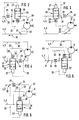
- the hydrostatic transmission generally designated 1 in FIG. 1, consists in the usual manner of a pump 2 and a hydraulic motor 3 in the form of axial piston machines which are inserted into a main circuit, generally designated 4, whose flow direction (arrow) depends on the pump 2 line section leading to the hydraulic motor 3 is the high-pressure line 5 and line section leading from the hydraulic motor 3 to the hydraulic pump 2 is the low-pressure line 6.
- the part of the transmission containing the pump 2 is designated by 7 and the part of the transmission containing the hydraulic motor 3 is designated by 8.
- the gear parts 7, 8 preferably form two parts that are independent of one another in terms of position and are connected only by the high-pressure line 5 and the low-pressure line 6 in the form of flexible hydraulic lines made of plastic or metal.
- the pump 2 and the hydraulic motor 3 are formed by constant displacement axial piston machines which are set up for operation in only one direction of rotation.
- the pump 2 is driven by a drive motor, not shown, by means of an input shaft 9.
- An output shaft 11 is assigned to the hydraulic motor 3, with which a consumer, such as a working machine or a running gear, can be driven.
- the closed circuit of the hydrostatic transmission 1 is connected in the area of the low pressure line 6 near the pump 2 to a hydraulic accumulator 14, by means of which the system is preloaded.
- the accumulator 14 is charged via a filling device with a pump 16 sucking from an oil tank 15 and a check valve 17 closing towards the pump 16, which are arranged in a hydraulic line section 18 and are also connected to the low pressure line 6 at 13.
- a heat exchanger 19 is arranged in the high-pressure line 5, by means of which the heat loss generated during operation is dissipated in a manner not shown.
- a bypass line 21, in which a pressure relief valve 22 is arranged extends between the high pressure line 5 and the low pressure line 6.
- the hydraulic motor 3 and the pump 2 are connected to the low-pressure line 6 by leak oil lines 23, 24, which ensures that the leak oil is discharged into the low-pressure line 6.
- valve spool 26 In order to prevent a high and therefore harmful, build-up in the low pressure line 6 due to the leakage oil line 23 pressure from the inside on the housing of the hydraulic motor 3 at low temperatures, is in the high pressure line 5 in the vicinity of the hydraulic motor 3 Throttle valve 25 is arranged, the valve spool 26 can be acted upon on both ends by a hydraulic cylinder 27, 28, which are assigned to the housing of the throttle valve 25. The valve spool 26 is acted upon as a function of the differential pressure upstream and downstream of a constant throttle 29 which is arranged in the low-pressure line 6 in the flow direction (arrow 30) in front of the line connection 31, through which the leak oil line 23 is connected to the low-pressure line 6.
- Constant throttle 29 emanate from the low pressure line 6 lines 32, 33, of which the line 32, which carries the higher pressure of the differential pressure, is connected to the hydraulic cylinder 27 and the line 33, which carries the lower pressure of the differential pressure, is connected to the hydraulic cylinder 28 .
- the line 33 is connected to the leak oil line 23 at 34, but the pressure existing behind the constant throttle 29 acts in both the leak oil line 23 and the line 33.
- a compression spring 35 is assigned to the hydraulic cylinder 28, the spring force of which is adjustable. The higher pressure of the differential pressure thus acts against the compression spring 35.
- the valve slide 26 can be adjusted inversely proportional to the pressure present in the area of the constant throttle 29, ie it can be continuously adjusted between a maximum and minimum position.
- the above-described hydrostatic transmission 1 is preferably intended for driving a fire water pump (not shown) for a ship, which is driven by the hydraulic motor 3 and preferably with the hydraulic motor 3, the throttle valve 25 and the constant throttle 29, a structural unit, in particular in the form of a block, forms. Due to the design of the high-pressure line 5 and the low-pressure line 6 as flexible lines, preferably plastic lines, the unit identified by 38 can be thrown overboard in a simple manner in order to bring the fire water pump into contact with the water in which the ship is located.
- the driven pump 2 conveys the hydraulic fluid present in the main line 4 in the direction of the arrow 30, as a result of which the hydraulic motor 3 is driven. If, for example, due to the cold and the resulting high viscosity in the low-pressure line 6, a pressure increase to a predeterminable value occurs, the valve slide 26 is automatically hydraulically shifted into a throttle position, so that in the present exemplary embodiment the delivery quantity reaching the hydraulic motor 3 is throttled so that the predeterminable pressure in the low-pressure line 6 is not exceeded.
- the transition between the functional positions of the valve spool 26 takes place approximately steadily with regard to the throttle effect, ie the throttle valve 25 is closed with increasing pressure in the low-pressure line 6 and opened with decreasing pressure.
- the pressure difference between the control lines 32, 33 corresponds to the pressure drop across the constant throttle 29, which occurs as a function of the flow rate and the viscosity of the operating fluid.
- the pressure drop at the constant throttle 29 thus behaves in proportion to the pressure drop in the entire low pressure line 6 and serves as a control variable for the position of the valve spool 26.
- the max. Throttling effect of valve spool 26 is defined by the max. permissible operating viscosity and that flow rate that, under the given system pressure - determined by the pressure relief valve 22 - in the low pressure line 6 the max. permissible pressure. As long as the valve slide 26 has not switched to free passage, the transmission is in the cold start area. The energy not absorbed by the hydraulic motor 3 is completely converted into heat at the throttle point of the pressure relief valve 22 and the useful energy flowing to the hydraulic motor 3 is partially converted into heat at the throttle point of the throttle valve 25 and thus serves to rapidly heat up the circuit.
- the full input power is always automatically taken up by the hydraulic pump 2, because the throttle valve 25 does not allow the entire flow to pass, and so a partial flow has to flow through the pressure relief valve 22 under the highest system pressure.
- This system pressure determines the size of the power consumption.
- the torque simultaneously output on the hydraulic motor 3 does not determine the operating pressure of the hydraulic pump 2 in this phase.
- the constant throttle 29 and the line connections 34, 36 for the control lines 32, 33 are located in the high-pressure line 5, specifically in front of the throttle valve 25.
- the constant throttle 29 is located and the line connections 31, 34 in the exemplary embodiment according to FIG. 3 likewise in the high-pressure line 5, but in the flow direction behind the throttle valve 25, ie between the latter and the hydraulic motor 3.
- the throttled delivery rate is supplied to the hydraulic motor 3.
- the throttle valve 25 is located in the low-pressure line 6, in the flow direction upstream of the line connection 31 for the leak oil line 23, the constant throttle 29 and the line connections 34, 36 for the control lines 32, 33 in the flow direction before the throttle valve 25, ie between the latter and the hydraulic motor 3 (Fig. 4) in the flow direction behind the throttle valve 25, i.e. can be arranged between the latter and the line connection 31 for the leak oil line 23 (FIG. 5) or in the high pressure line 5 (FIG. 6).
- valve slide 26 only between two functional positions (open, closed or throttled).
- the amount of flow is thus throttled before the line connection 31 for the leak oil line 23, so that the low pressure line 6, i.e. at least in the area of the line connection 31 for the leak oil line 23, no harmful pressure can build up.
Description
Die Erfindung bezieht sich auf ein hydrostatisches Getriebe nach dem Oberbegriff des Anspruchs 1. Ein derartiges Getriebe ist allgemein bekannt.The invention relates to a hydrostatic transmission according to the preamble of
Bei einem hydrostatischen Getriebe können sich dann Kaltstartschwierigkeiten einstellen, wenn das im hydraulischen Kreislauf des hydrostatischen Getriebes strömende hydraulische Medium unterkühlt und deshalb zähflüssig wird. Diese Schwierigkeit vergrößert sich mit zunehmendem Abstand zwischen Pumpe und Hydromotor, d.h. mit zunehmender Länge der Hauptleitung, in der die Pumpe und der Hydromotor angeordnet sind.In the case of a hydrostatic transmission, cold start difficulties can arise if the hydraulic medium flowing in the hydraulic circuit of the hydrostatic transmission becomes supercooled and therefore becomes viscous. This difficulty increases with the distance between the pump and the hydraulic motor, i.e. with increasing length of the main line in which the pump and the hydraulic motor are arranged.
Mit zunehmender Länge der Hauptleitung stellt sich ein weiteres Problem in der Rückführung der Leckage des Hydromotors in den Tank. Um hier eine lange, sich vom Hydromotor bis in die Nähe der Pumpe erstreckende Leckageleitung zu vermeiden, ist schon vorgeschlagen worden, die Leckageleitung des Hydromotors mit der Niederdruckleitung der Hauptleitung zu verbinden. Bei einer solchen Ausgestaltung ist dann mit Überlastungen und Funktionsschwierigkeiten des Hydromotors zu rechnen, wenn ein Druckanstieg in der Niederdruckleitung stattfindet, was ebenfalls durch Kälte, z.B. durch ein zumindest stellenweise "Einfrieren" der Niederdruckleitung hervorgerufen werden kann, da die Viskosität der Betriebsflüssigkeit, die Höhe des Förderstromes sowie der Leitungswiderstand den Druck in der Rücklaufleitung und somit auch den Druck im Gehäuse des Hydromotors bestimmen. Aus konstruktiven Gründen und mit Rücksicht auf die Dichtungen des Hydromotors, Z.B. eine Wellendichtung, ist dabei die max. zulässige Druckhöhe sehr begrenzt. Zur Vermeidung unzulässiger Drücke müssen die Viskositätswerte der Betriebsflüssigkeit in Bezug auf die auftretenden Betriebs- und Umgebungstemperaturen entsprechend ausgewählt werden. Bei extremen tiefen Temperaturen und bei hohen Leitungswiderständen genügt dies in den meisten Fällen nicht, und es muß insbesondere bei Startvorgängen die Betriebsflüssigkeit entsprechend vorgewärmt werden, bevor ein Betrieb unter Nennleistung möglich ist. Es wäre z.B. möglich, die Betriebsflüssigkeit vor dem Starten durch eine Fremdbeheizung zu erwärmen.As the length of the main line increases, another problem arises in returning the leakage of the hydraulic motor to the tank. In order to avoid a long leakage line extending from the hydraulic motor to the vicinity of the pump, it has already been proposed to connect the leakage line of the hydraulic motor to the low-pressure line of the main line. With such a configuration, overloads and functional difficulties of the hydraulic motor are to be expected if there is an increase in pressure in the low-pressure line, which can also be caused by cold, for example by at least in places "freezing" of the low-pressure line, since the viscosity of the operating fluid, the height of the flow rate and the line resistance determine the pressure in the return line and thus also the pressure in the housing of the hydraulic motor. For design reasons and considering the seals of the hydraulic motor, eg a shaft seal, this is the Max. permissible head is very limited. To avoid inadmissible pressures, the viscosity values of the operating fluid must be selected accordingly in relation to the operating and ambient temperatures that occur. At extremely low temperatures and with high line resistances, this is not sufficient in most cases, and the operating fluid must be preheated accordingly, especially during start-up operations, before operation at nominal power is possible. For example, it would be possible to heat the operating fluid by means of external heating before starting.
Es ist auch schon eine Bypaßschaltung vorgeschlagen worden, bestehend aus einer in einem, die Hochdruckleitung und die Niederdruckleitung miteinander verbindenden Bypaß angeordneten Ventilkette mit einem Überdruckventil, das so eingestellt ist, daß unter Berücksichtigung des max. zulässigen Rücklaufdruckes nur ein Bruchteil des normalen Förderströmes in der Hauptleitung zirkuliert. Mit der am Überdruckventil anfallenden Verlustwärme kann der Kreislauf aufgeheizt werden.A bypass circuit has also already been proposed, consisting of a valve chain arranged in a bypass connecting the high-pressure line and the low-pressure line with a pressure relief valve, which is set such that, taking into account the max. permissible return pressure circulates only a fraction of the normal flow in the main line. The circuit can be heated up with the heat loss at the pressure relief valve.
Diese Maßnahmen sind aus folgenden Gründen nachteilig. Für die Vorwärmung eignet sich im allgemeinen nur der vorhandene Getriebebehälter für die Hydraulikflüssigkeit. Dabei wird die Hydraulikflüssigkeit in der Hauptleitung nicht erfaßt, und deshalb besteht die Gefahr, daß beim Anfahren der Druck in der Niederdruckleitung und somit auch der Druck im Gehäuse des Hydromotors auf einen unzulässigen Wert ansteigt, bei dem mit einer Beschädigung des Hydromotors zu rechnen ist.These measures are disadvantageous for the following reasons. In general, only the existing transmission container for the hydraulic fluid is suitable for preheating. The hydraulic fluid in the main line is not detected, and therefore there is a risk that when starting up the pressure in the low pressure line and thus also the pressure in the housing of the hydraulic motor will rise to an impermissible value at which damage to the hydraulic motor is to be expected.
Der Erfindung liegt die Aufgabe zugrunde, ein hydrostatisches Getriebe der eingangs bezeichneten Art so auszugestalten, daß das Gehäuse des Hydromotors von unzulässig hohen Drücken der Hauptleitung freigestellt ist.The invention has for its object to design a hydrostatic transmission of the type mentioned in such a way that the housing of the hydraulic motor is released from impermissibly high pressures of the main line.
Diese Aufgabe wird durch die kennzeichnenden Merkmale des Anspruchs 1 gelöst.This object is achieved by the characterizing features of
Bei der erfindungsgemäßen Ausgestaltung wird der Kreislauf an einer Stelle in Strömungsrichtung vor dem Leitungsanschluß für die Leckölleitung des Hydromotors gedrosselt, wenn der Druck in der Hauptleitung, der sich durch die Niederdruckleitung auf die Leckölleitung und das Motorgehäuse auswirken kann, einen vorbestimmten Wert übersteigt. Es ist dabei im Rahmen der Erfindung möglich, den Durchflußquerschnitt des Ventils in Abhängigkeit entweder vom Druck oder von der Temperatur in der Hauptleitung zu verstellen. Die letztere Maßgabe führt ebenfalls zu einer vorteilhaften Lösung, weil bei niedrigen Temperaturen die Viskosität der Hydraulikflüssigkeit zunimmt, was ebenfalls zu den eingangs beschriebenen Problemen führt und oft Ursache dieser Probleme ist. Dabei kann das Ventil elektrisch, hydraulisch oder auch mechanisch gesteuert sein. Sobald der Druck sinkt oder die Temperatur des hydraulischen Mediums steigt, wird das Ventil vorzugsweise kontinuierlich geöffnet bzw. sein Durchflußquerschnitt kontinuierlich vergrößert. Im Normal betrieb, d.h. bei normalen Druckverhältnissen oder bei normaler Außentemperatur bzw. nach dem Warmlaufen des Getriebes kann die Drosselung ganz aufgehoben werden.In the embodiment according to the invention, the circuit is throttled at a point in the flow direction upstream of the line connection for the leak oil line of the hydraulic motor when the pressure in the main line, which can affect the leak oil line and the motor housing through the low pressure line, exceeds a predetermined value. It is possible within the scope of the invention to adjust the flow cross section of the valve depending on either the pressure or the temperature in the main line. The latter requirement also leads to an advantageous solution because the viscosity of the hydraulic fluid increases at low temperatures, which likewise leads to the problems described at the outset and is often the cause of these problems. The valve can be controlled electrically, hydraulically or mechanically. As soon as the pressure drops or the temperature of the hydraulic medium rises, the valve is preferably opened continuously or its flow cross section is continuously increased. In normal operation, i.e. under normal pressure conditions or at normal outside temperature or after the gearbox has warmed up, the throttling can be completely removed.
Bei der erfindungsgemäßen Ausgestaltung kann es zu einem schädlichen hohen Druck im Bereich des Leitungsanschlusses der Leckölleitung gar nicht kommen, da das erfindungsgemäße Ventil die Zufuhr der Hydraulikflüssigkeit zum Leitungsanschluß drosselt bzw. stoppt und ein schädlich hoher Druck sich gar nicht auswirken kann. Dabei kann das Ventil gemäß den Ansprüchen 2 bis 4 vor dem Leitungsanschluß für die Leckölleitung und sowohl in der Hochdruckleitung als auch in der Niederdruckleitung angeordnet sein, wobei sich gemäß Anspruch 2 eine Anordnung des Ventils in der Nähe des Hydromotors aus Gründen einer einfachen und funktionssicheren Bauweise empfiehlt.In the embodiment according to the invention, there can be no harmful high pressure in the area of the line connection of the leak oil line, since the valve according to the invention throttles or stops the supply of the hydraulic fluid to the line connection and a harmful high pressure cannot have any effect. The valve can be arranged according to claims 2 to 4 upstream of the line connection for the leak oil line and both in the high pressure line and in the low pressure line. an arrangement of the valve in the vicinity of the hydraulic motor is recommended for reasons of a simple and functionally reliable design.
Die Ausbildung nach Anspruch 5 trägt zu weiteren Vereinfachung der erfindungsgemäßen Ausgestaltung bei, wobei sich eine automatische Verstellung des Ventils ergibt, und zwar insbesondere ohne zusätzlicher Steuersignale aus dem Bereich der Pumpe, so daß auch keine langen Steuerleitungen zwischen dem Bereich, in dem die Pumpe angeordnet ist, und dem Ventil erforderlich sind.The embodiment according to
Bei der Ausgestaltung nach Anspruch 6 wird der Ventilkörper des Ventils in Abhängigkeit vom Druckabfall einer vorzugsweise konstanten Drossel beaufschlagt, die sowohl in der Hochdruckleitung als auch in der Niederdruckleitung und sowohl vor als auch hinter dem Ventil angeordnet sein kann. Wesentlich ist, daß die Drossel in Strömungsrichtung vor dem Leitungsanschluß der Leckölleitung angeordnet ist, so daß sich ein schädlich hoher Druck in der Niederdruckleitung nicht in den Leckölkanal und somit auch nicht in das Gehäuse des Hydromotors auswirken kann.In the embodiment according to claim 6, the valve body of the valve is acted upon as a function of the pressure drop of a preferably constant throttle, which can be arranged both in the high-pressure line and in the low-pressure line and both upstream and downstream of the valve. It is essential that the throttle is arranged in the flow direction upstream of the line connection of the leak oil line, so that a damagingly high pressure in the low pressure line cannot affect the leak oil channel and thus not the housing of the hydraulic motor.
Die Ausbildung nach Anspruch 11 ist aus konstruktiven Gründen und Handhabungsgründen vorteilhaft.The design according to
Gemäß Anspruch 12 ist ein Umlauf der Hydraulikflüssigkeit in der Hauptleitung bei Aufrechterhaltung eines bestimmten Arbeitsdruckes gewährleistet, wenn die Hauptleitung hinter dem Bypaß verstopft bzw. in der Durchströmung beeinträchtigt sein sollte. An der Drossel des Ventils und/oder an der des Überdruckventils entsteht eine Erwärmung, die vorteilhaft zum Aufwärmen der Hydraulikflüssigkeit bei Kaltstartschwierigkeiten ausgenutzt werden kann.According to claim 12, a circulation of the hydraulic fluid in the main line is ensured while maintaining a certain working pressure if the main line behind the bypass is blocked or the flow is impaired. At the throttle of the valve and / or at that of the pressure relief valve, heating occurs which can advantageously be used to warm up the hydraulic fluid in the event of cold start difficulties.
Die erfindungsgemäße Ausgestaltung eignet sich sowohl für einen offenen Kreislauf als auch vorzugsweise für einen geschlossenen Kreislauf.The configuration according to the invention is suitable both for an open circuit and preferably for a closed circuit.
Aufgrund der Unabhängigkeit zwischen dem die Pumpe enthaltenden Getriebeteil und dem den Hydromotor enthaltenden Getriebeteil eignet sich die erfindungsgemäße Ausgestaltung insbesondere für solche Verwendungsfälle, in denen die vorgenannten Getriebeteile lediglich durch die Hochdruckleitung und die Niederdruckleitung miteinander verbunden sind, und zwar in Form von flexiblen Leitungen wie Schläuchen. In einem solchen Fall kann der den Hydromotor enthaltende Getriebeteil unabhängig von dem die Pumpe enthaltenden Getriebeteil verlagert werden. Ein bevorzugter Verwendungsfall für ein erfindungsgemäß ausgestaltetes hydrostatisches Getriebe ist der Schiffbau, da auch bei einem großen Abstand zwischen der Pumpe und dem Hydromotor eine praktische Anordnung und Handhabung des den Hydromotor enthaltenden Getriebeteils möglich ist. Es ist möglich, den den Hydromotor enthaltenden Getriebeteil bei Verwendung als Antrieb für eine Löschwasserpumpe auf einem Schiff über Bord zu werfen, um die vom Hydromotor angetriebene Wasserpumpe, die mit dem Hydromotor und dem besonderen erfindungsgemäßen Bauteilen eine Baueinheit bilden kann, in Kontakt mit dem das Schiff tragenden Wasser zu bringen, wobei aufgrund der erfindungsgemäßen Ausgestaltung Überlastungen des Hydromotors und Funktionsschwierigkeiten auch bei verhältnismäßig großer Kälte vermieden sind. Nach Beendigung des Einsatzes kann der den Hydromotor enthaltende Getriebeteil wieder an Bord gezogen und raumsparend gelagert werden.Because of the independence between the transmission part containing the pump and the transmission part containing the hydraulic motor, the configuration according to the invention is particularly suitable for those applications in which the aforementioned transmission parts are connected to one another only by the high-pressure line and the low-pressure line, in the form of flexible lines such as hoses . In such a case, the transmission part containing the hydraulic motor can be displaced independently of the transmission part containing the pump. A preferred application for a hydrostatic transmission designed according to the invention is shipbuilding, since even with a large distance between the pump and the hydraulic motor, a practical arrangement and handling of the transmission part containing the hydraulic motor is possible. It is possible to throw the gear part containing the hydraulic motor when used as a drive for an extinguishing water pump on a ship overboard to the water pump driven by the hydraulic motor, which can form a structural unit with the hydraulic motor and the special components according to the invention, in contact with that Bring ship carrying water, whereby due to the inventive design overloads of the hydraulic motor and functional difficulties are avoided even in relatively great cold. After completion of the operation, the gear part containing the hydraulic motor can be pulled on board again and stored in a space-saving manner.
Nachfolgend wird die Erfindung anhand von in vereinfachten Zeichnungen dargestellten bevorzugten Ausführungsbeispielen näher erläutert. Es zeigt
- Fig. 1
- einen Steuerplan für einen erfindungsgemäß ausgestaltetes hydrostatisches Getriebe;
- Fig. 2 bis 6
- Abwandlungen des hydrostatischen Getriebes.
- Fig. 1
- a control plan for a hydrostatic transmission designed according to the invention;
- 2 to 6
- Modifications of the hydrostatic transmission.
Das in Fig. 1 allgemein mit 1 bezeichnete hydrostatische Getriebe besteht in üblicher Weise aus einer Pumpe 2 und einem Hydromotor 3 in Form von Axialkolbenmaschinen, die in eine allgemein mit 4 bezeichnete Hauptleitung geschlossenen Kreislaufs eingesetzt sind, deren strömungsrichtungabhängig (Pfeil) von der Pumpe 2 zum Hydromotor 3 führender Leitungsabschnitt die Hochdruckleitung 5 und deren vom Hydromotor 3 zur Hydropumpe 2 führender Leitungsabschnitt die Niederdruckleitung 6 ist. Der die Pumpe 2 enthaltende Teil des Getriebes ist mit 7 und der den Hydromotor 3 enthaltende Teil des Getriebes ist mit 8 bezeichnet. Vorzugsweise bilden die Getriebeteile 7, 8 zwei voneinander positionsmäßig unabhängige Teile, die lediglich durch die Hochdruckleitung 5 und die Niederdruckleitung 6 in Form von flexiblen Hydraulikleitungen aus Kunststoff oder Metall verbunden sind.The hydrostatic transmission, generally designated 1 in FIG. 1, consists in the usual manner of a pump 2 and a
Beim vorliegenden Ausführungsbeispiel werden die Pumpe 2 und der Hydromotor 3 durch Axialkolbenmaschinen konstanten Hubvolumens gebildet, die für den Betrieb in nur eine Drehrichtung eingerichtet sind. Die Pumpe 2 wird durch einen nicht dargestellten Antriebsmotor mittels einer Eingangswelle 9 angetrieben. Dem Hydromotor 3 ist eine Ausgangswelle 11 zugeordnet, mit der sich ein Verbraucher, wie eine Arbeitsmaschine oder auch ein Fahrwerk, antreiben läßt.In the present exemplary embodiment, the pump 2 and the
Der geschlossene Kreislauf des hydrostatischen Getriebes 1 ist im Bereich der Niederdruckleitung 6 nahe der Pumpe 2 mit einem hydraulischen Speicher 14 verbunden, durch den das System vorgespannt wird. Der Speicher 14 wird über eine Fülleinrichtung mit einer aus einem Ölbehälter 15 saugenden Pumpe 16 und einem zur Pumpe 16 hin schließenden Rückschlagventil 17 aufgeladen, die in einem hydraulischen Leitungsabschnitt 18 angeordnet und bei 13 ebenfalls mit der Niederdruckleitung 6 verbunden sind. In der Hochdruckleitung 5 ist ein Wärmetauscher 19 angeordnet, mittels dem die im Betrieb entstandene Verlustwärme in nicht dargestellter Weise abgeführt wird. In der Nähe der Pumpe 2 erstreckt sich zwischen der Hochdruckleitung 5 und der Niederdruckleitung 6 eine Bypaßleitung 21, in der ein Überdruckventil 22 angeordnet ist.The closed circuit of the
Der Hydromotor 3 und die Pumpe 2 sind durch Leckölleitungen 23, 24 mit der Niederdruckleitung 6 verbunden, wodurch die Abführung des Lecköls in die Niederdruckleitung 6 hinein gewährleistet ist.The
Um zu verhindern, daß bei kalten Temperaturen ein aufgrund niedriger Viskosität hoher und deshalb schädlicher, sich in der Niederdruckleitung 6 aufbauender Druck durch die Leckölleitung 23 von innen auf das Gehäuse des Hydromotors 3 wirkt, ist in der Hochdruckleitung 5 in der Nähe des Hydromotors 3 ein Drosselventil 25 angeordnet, dessen Ventilschieber 26 zu beiden Stirnseiten durch jeweils einen Hydraulikzylinder 27, 28 beaufschlagbar ist, die dem Gehäuse des Drosselventils 25 zugeordnet sind. Die Beaufschlagung des Ventilschiebers 26 erfolgt in Abhängigkeit vom Differenzdruck vor und hinter einer Konstantdrossel 29, die in der Niederdruckleitung 6 in Strömungsrichtung (Pfeil 30) vor dem Leitungsanschluß 31 angeordnet ist, durch den die Leckölleitung 23 mit der Niederdruckleitung 6 verbunden ist. Vor und hinter der Konstantdrossel 29 gehen von der Niederdruckleitung 6 Leitungen 32, 33 aus, von denen die mit 32 bezeichnete, den höheren Druck des Differenzdruckes führende Leitung mit dem Hydraulikzylinder 27 und die mit 33 bezeichnete, den geringeren Druck des Differenzdrucks führende Leitung mit dem Hydraulikzylinder 28 verbunden ist. Die Leitung 33 ist bei 34 an die Leckölleitung 23 angeschlossen, jedoch wirkt sowohl in der Leckölleitung 23 als auch in der Leitung 33 der hinter der Konstantdrossel 29 vorhandene Druck. Dem Hydraulikzylinder 28 ist eine Druckfeder 35 zugeordnet, deren Federkraft verstellbar ist. Es wirkt somit der höhere Druck des Differenzdruckes gegen die Druckfeder 35. Der Ventilschieber 26 ist umgekehrt proportional zum im Bereich der Konstantdrossel 29 vorhandenen Druck verstellbar, d.h. er ist kontinuierlich zwischen einer Maximal- und Minimalstellung verstellbar.In order to prevent a high and therefore harmful, build-up in the low pressure line 6 due to the
Das vorbeschriebene hydrostatische Getriebe 1 ist vorzugsweise für den Antrieb einer Löschwasserpumpe (nicht dargestellt) für ein Schiff bestimmt, die vom Hydromotor 3 angetrieben wird und vorzugsweise mit dem Hydromotor 3, dem Drosselventil 25 und der Konstantdrossel 29 eine Baueinheit, insbesondere in Form eines Blockes, bildet. Aufgrund der Ausführung der Hochdruckleitung 5 und der Niederdruckleitung 6 als flexible Leitungen, vorzugsweise Kunststoffleitungen, kann die mit 38 bezeichente Baueinheit in einfacher Weise über Bord geworfen werden, um die Löschwasserpumpe in Kontakt mit dem Wasser zu bringen, in dem das Schiff sich befindet. Da die Leckölleitung 23 an die Niederdruckleitung 6 angeschlossen ist, bedarf es keiner besonderen, zur die Pumpe enthaltenden Baueinheit 7 zurückführenden Leitungen, die im vorliegenden Fall sehr lang, z.B. 20 m und mehr, ausgeführt werden müßten, was die Herstellungskosten erheblich verteuern und die Handhabung erschweren würde.The above-described
Im folgenden wird die Funktion des hydrostatischen Getriebes 1 beschrieben. Die angetriebene Pumpe 2 befördert die in der Hauptleitung 4 vorhandene Hydraulikflüssigkeit in Pfeilrichtung 30, wodurch der Hydromotor 3 angetrieben wird. Stellt sich z.B. aufgrund von Kälte und dadurch hervorgerufener hoher Viskosität in der Niederdruckleitung 6 eine Druckerhöhung auf einen vorbestimmbaren Wert ein, dann wird automatisch der Ventilschieber 26 hydraulisch in eine Drosselstellung verschoben, wodurch beim vorliegenden Ausführungsbeispiel die zum Hydromotor 3 gelangende Fördermenge so gedrosselt wird, daß der vorbestimmbare Druck in der Niederdruckleitung 6 nicht überschritten wird. Der Übergang zwischen den Funktionsstellungen des Ventilschiebers 26 erfolgt im Hinblick auf die Drosselwirkung angenähert stetig, d.h. mit zunehmendem Druck in der Niederdruckleitung 6 wird das Drosselventil 25 geschlossen und mit abnehmendem Druck geöffnet. Die Druckdifferenz zwischen den Steuerleitungen 32, 33 entspricht dem Druckabfall an der Konstantdrossel 29, welcher in Abhängigkeit von der Durchflußmenge und der Viskosität der Betriebsflüssigkeit entsteht. Der Druckabfall an der Konstantdrossel 29 verhält sich damit proportional zum Druckabfall in der gesamten Niederdruckleitung 6 und dient als Regelgröße für die Stellung des Ventilschiebers 26. Ist beim Startvorgang, insbesondere aufgrund hoher Temperatur, die Viskosität so niedrig, daß selbst bei vollem Förderstrom der Pumpe 2 der zulässige Druckabfall in der Niederdruckleitung 6 nicht überschritten wird, so ist der analog entsprechende Druckabfall an der Konstantdrossel 29 nicht in der Lage, den Ventilschieber 26 gegen die Wirkung der Druckfeder 35 aus seiner Stellung für freien Durchgang zu bewegen, ist dagegen die Viskosität z.B. aufgrund niedriger Temperatur zu hoch, dann zwingt der Differenzdruck an der Konstantdrossel 29 den Ventilschieber 26 in eine Drosselstellung, die den Zufluß zum Hydromotor 3 vermindert und somit die zu einer Druckerhöhung in der Niederdruckleitung 6 führende Wirkung der zu hohen Viskosität kompensiert. Die dabei vom Hydromotor 3 nicht aufgenommene Förderstrommenge fließt unter den max. Betriebsdruck durch das Überdruckventil 22 ab. Die max. Drosselwirkung des Ventilschiebers 26 ist definiert durch die max. zulässige Betriebsviskosität und durch jenen Förderstrom, der unter dem gegebenen Systemdruck - bestimmt durch das Überdruckventil 22 - in der Niederdruckleitung 6 den max. zulässigen Druck bewirkt. Solange der Ventilschieber 26 nicht auf freien Durchgang geschaltet hat, befindet sich das Getriebe im Kaltstartbereich. Die vom Hydromotor 3 nicht aufgenommene Energie wird an der Drosselstelle des Überdruckventils 22 vollständig und die Nutzenergie, die zum Hydromotor 3 fließt, an der Drosselstelle des Drosselventils 25 teilweise in Wärme umgewandelt und dient so der raschen Aufheizung des Kreislaufs. Während des Kaltstartvorganges wird automatisch von der Hydropumpe 2 immer die volle Eingangsleistung aufgenommen, weil das Drosselventil 25 nicht den gesamten Förderstrom passieren läßt und so ein Teilstrom über das Überdruckventil 22 unter dem höchsten Systemdruck abfließen muß. Dieser Systemdruck bestimmt die Größe der Leistungsaufnahme. Das am Hydromotor 3 gleichzeitig abgegebene Drehmoment bestimmt in dieser Phase den Betriebsdruck der Hydropumpe 2 nicht.The function of the
In den Fig. 2 bis 6 sind vorteilhafte Alternativen für die Anordnung des Drosselventils 25 und der Konstantdrossel 29 dargestellt. Beim Ausführungsbeispiel gemäß Fig. 2 befinden sich die Konstantdrossel 29 und die Leitungsanschlüsse 34, 36 für die Steuerleitungen 32, 33 in der Hochdruckleitung 5, und zwar vor dem Drosselventil 25. Im Gegensatz dazu befinden sich die Konstantdrossel 29 und die Leitungsanschlüsse 31, 34 beim Ausführungsbeispiel gemäß Fig. 3 zwar ebenfalls in der Hochdruckleitung 5, jedoch in Strömungsrichtung hinter dem Drosselventil 25, d.h. zwischen letzterem und dem Hydromotor 3. Bei den vorbeschriebenen drei Ausgestaltungen wird dem Hydromotor 3 jeweils die gedrosselte Fördermenge zugeführt.2 to 6 advantageous alternatives for the arrangement of the
Bei den Ausführungsbeispielen gemäß Fig. 4 bis 6 befindet sich das Drosselventil 25 in der Niederdruckleitung 6, und zwar in Strömungsrichtung vor dem Leitungsanschluß 31 für die Leckölleitung 23, wobei die Konstantdrossel 29 und die Leitungsanschlüsse 34, 36 für die Steuerleitungen 32, 33 in Strömungsrichtung vor dem Drosselventil 25, d.h. zwischen letzterem und dem Hydromotor 3 (Fig. 4) in Strömungsrichtung hinter dem Drosselventil 25, d.h. zwischen letzterem und dem Leitungsanschluß 31 für die Leckölleitung 23 (Fig. 5) oder in der Hochdruckleitung 5 (Fig. 6) angeordnet sein können.4 to 6, the
Im Rahmen der Erfindung ist es auch möglich, den Ventilschieber 26 nur zwischen zwei Funktionsstellungen (offen, zu oder gedrosselt) verstellbar anzuordnen.In the context of the invention it is also possible to arrange the
Bei allen Ausführungsbeispielen wird somit die Strömungsmenge vor dem Leitungsanschluß 31 für die Leckölleitung 23 gedrosselt, so daß sich in der Niederdruckleitung 6, d.h. zumindest im Bereich des Leitungsanschlusses 31 für die Leckölleitung 23, kein schädlicher Druck aufbauen kann.In all of the exemplary embodiments, the amount of flow is thus throttled before the
Claims (14)
- Hydrostatic transmission (1) having a pump (2) and a hydraulic motor (3) arranged in a main line (4) having a low pressure line and a high pressure line, an oil drain line (23) of the hydraulic motor (3) being connected to the low pressure line (6) of the main line (4),
characterised in that a valve (25) having a valve body (26) and with adjustable passage cross-section is arranged before - in the direction of flow (arrow 30) - the line connection (31) of the oil drain line (23), which valve reduces the passage cross-section with increasing pressure or at low temperatures in the main line (4). - Hydrostatic transmission according to claim 1, characterised in that the valve (25) is arranged near the hydraulic motor (3).
- Hydrostatic transmission according to any one of claims 1 to 2, characterised in that the valve (25) is arranged in the high pressure line (5).
- Hydrostatic transmission according to any one of claims 1 to 2, characterised in that the valve (25) is arranged in the low pressure line (6).
- Hydrostatic transmission according to any one of claims 1 to 4, characterised in that the valve body (26) of the valve (25) can be acted on by the pressure before - in the direction of flow (30) - a throttle (29) arranged preferably near the hydraulic motor (3) in the main line (4).
- Hydrostatic transmission according to claim 5, characterised in that the valve body (26) can be acted on its other side by the pressure after - in the direction of flow (30) - the throttle (29).
- Hydrostatic transmission according to claim 5 or 6, characterised in that the valve body (26) can be urged against a spring (35) by the pressure before the throttle (29).
- Hydrostatic transmission according to any one of claims 5 to 7, characterised in that the throttle (29) is arranged in the low pressure line (6) between the hydraulic motor (3) and the line connection (31) for the oil drain line (23) (Fig. 1).
- Hydrostatic transmission according to any one of claims 5 to 7, characterised in that the throttle (29) is arranged in the high pressure line (5) (Fig. 6).
- Hydrostatic transmission according to any one of claims 5 to 9, characterised in that the throttle (29) is arranged before or after - in the direction of flow (30) - the valve (25) (Fig. 2, 4 and 6 or Fig. 1, 3 and 5).
- Hydrostatic transmission according to any one of claims 1 to 10, characterised in that the valve (25), the throttle (29) and/or the line connections (34, 36) are arranged in a constructional unit (38) or constructional part comprising the hydraulic motor (3).
- Hydrostatic transmission according to any one of claims 1 to 11, characterised in that, preferably near the pump (2), a bypass line (21) is provided between the high pressure line (5) and the low pressure line (6), in which a pressure relief valve (22) is arranged.
- Hydrostatic transmission according to any one of claims 1 to 12, characterised in that the pump (2) is connected to the low pressure line (6) by an oil drain line (24).
- Hydrostatic transmission according to any one of claims 1 to 13, characterised in that it is a closed circuit hydrostatic transmission.
Applications Claiming Priority (2)
| Application Number | Priority Date | Filing Date | Title |
|---|---|---|---|
| DE3812300 | 1988-04-13 | ||
| DE3812300A DE3812300C1 (en) | 1988-04-13 | 1988-04-13 |
Publications (3)
| Publication Number | Publication Date |
|---|---|
| EP0337124A2 EP0337124A2 (en) | 1989-10-18 |
| EP0337124A3 EP0337124A3 (en) | 1991-06-26 |
| EP0337124B1 true EP0337124B1 (en) | 1994-05-18 |
Family
ID=6351897
Family Applications (1)
| Application Number | Title | Priority Date | Filing Date |
|---|---|---|---|
| EP89104312A Expired - Lifetime EP0337124B1 (en) | 1988-04-13 | 1989-03-10 | Hydrostatic transmission |
Country Status (3)
| Country | Link |
|---|---|
| US (1) | US5048295A (en) |
| EP (1) | EP0337124B1 (en) |
| DE (2) | DE3812300C1 (en) |
Cited By (1)
| Publication number | Priority date | Publication date | Assignee | Title |
|---|---|---|---|---|
| DE102014011073B3 (en) * | 2014-07-30 | 2015-11-12 | Danfoss Power Solutions Gmbh & Co. Ohg | 1Motordrehzahlbegrenzungsvorrichtung |
Families Citing this family (19)
| Publication number | Priority date | Publication date | Assignee | Title |
|---|---|---|---|---|
| US5203172A (en) * | 1990-05-17 | 1993-04-20 | Simpson Alvin B | Electromagnetically powered hydraulic engine |
| US5170692A (en) * | 1991-11-04 | 1992-12-15 | Vickers, Incorporated | Hydraulic control system |
| US5235810A (en) * | 1992-09-28 | 1993-08-17 | Tecumseh Products Company | Conduit valve providing wide neutral in a hydrostatic transmission |
| US5355675A (en) * | 1993-08-31 | 1994-10-18 | Western Atlas International, Inc. | Stabilized speed-control system for a hydrostatic transmission |
| US5533333A (en) * | 1994-04-29 | 1996-07-09 | Atlantic Richfield Company | Method and regulator for regulating the air pressure of a pressurized vessel |
| US5467596A (en) * | 1994-11-09 | 1995-11-21 | Applied Power Inc. | Unitary electro-hydraulic rotary actuator for automotive convertible top |
| US6338247B1 (en) * | 1998-11-20 | 2002-01-15 | Sauer-Danfoss Inc. | System for controlling a hydraulic vehicle drive |
| US6336325B1 (en) | 1999-12-07 | 2002-01-08 | Sauer-Danfoss Inc. | Hydrostatic loop dump valve for reducing input torque required by hydrostatic unit |
| US6382595B1 (en) * | 2000-07-26 | 2002-05-07 | Schlumberger Technology Corporation | Differential hydrostatic transmission system |
| US6666655B2 (en) * | 2001-05-11 | 2003-12-23 | Delphi Technologies, Inc. | Hydraulic pump nozzle and method of use |
| US20040177610A1 (en) * | 2003-03-11 | 2004-09-16 | Hendrickson Barry M. | Broad range speed control for hydraulic motors |
| DE10342893A1 (en) * | 2003-09-17 | 2005-05-25 | Zf Friedrichshafen Ag | Process to pre-heat automotive gearbox components circulates engine oil to the gearbox during the cold start phase |
| DE102008061350A1 (en) * | 2008-12-10 | 2010-06-17 | Robert Bosch Gmbh | Hydrostatic system with a hydropneumatic accumulator |
| US20110179781A1 (en) * | 2010-01-27 | 2011-07-28 | Charles Leon Fant | Hydraulic drive system for use in driven systems |
| WO2011133072A1 (en) * | 2010-04-19 | 2011-10-27 | Parker Hannifin Ab | Arrangement for operating a hydraulic device |
| WO2015034499A1 (en) * | 2013-09-05 | 2015-03-12 | Volvo Construction Equipment Ab | Hydrostatic transmission for construction vehicle |
| DE102014209387B3 (en) * | 2014-05-16 | 2015-09-24 | Rausch & Pausch Gmbh | hydraulic system |
| ITUB20150172A1 (en) * | 2015-03-04 | 2016-09-04 | Mecc Breganzese S P A | HYDRAULIC EQUIPMENT FOR EXCAVATORS AND OPERATING MACHINES IN GENERAL |
| FR3033528B1 (en) * | 2015-03-13 | 2017-03-31 | Poclain Hydraulics Ind | HYDRAULIC ASSISTANCE CIRCUIT WITH LOW PRESSURE EXCHANGER |
Family Cites Families (10)
| Publication number | Priority date | Publication date | Assignee | Title |
|---|---|---|---|---|
| US2655000A (en) * | 1942-03-23 | 1953-10-13 | Hydraulik As | Pump and motor hydraulic system and control valve means therefor |
| US2415603A (en) * | 1943-08-26 | 1947-02-11 | Hydraulic Dev Corp Inc | Hydraulic constant speed control system for parallel-connected hydraulic motors |
| US2632301A (en) * | 1950-08-31 | 1953-03-24 | James H Brodie | Hydraulic braking apparatus |
| US3218797A (en) * | 1964-07-23 | 1965-11-23 | New York Air Brake Co | Starting system |
| BE757640A (en) * | 1969-10-16 | 1971-04-16 | Borg Warner | HYDRAULIC SYSTEMS, ESPECIALLY FOR THE REGULATION OF A VARIABLE FLOW PUMP |
| FR2104897B1 (en) * | 1971-03-17 | 1974-03-22 | Poclain Sa | |
| GB1372809A (en) * | 1973-04-04 | 1974-11-06 | Priestman Bros Ltd | Hydraulic ram circuit |
| US3999386A (en) * | 1975-09-11 | 1976-12-28 | Sundstrand Corporation | Overspeed protection control for an engine |
| US4255091A (en) * | 1979-02-05 | 1981-03-10 | Dike Equipment Corporation | Structural unit for hydraulic systems |
| US4713936A (en) * | 1985-11-18 | 1987-12-22 | Deere & Company | Motor seal protector valve |
-
1988
- 1988-04-13 DE DE3812300A patent/DE3812300C1/de not_active Expired
-
1989
- 1989-03-10 DE DE58907669T patent/DE58907669D1/en not_active Expired - Fee Related
- 1989-03-10 EP EP89104312A patent/EP0337124B1/en not_active Expired - Lifetime
- 1989-03-15 US US07/324,240 patent/US5048295A/en not_active Expired - Lifetime
Cited By (1)
| Publication number | Priority date | Publication date | Assignee | Title |
|---|---|---|---|---|
| DE102014011073B3 (en) * | 2014-07-30 | 2015-11-12 | Danfoss Power Solutions Gmbh & Co. Ohg | 1Motordrehzahlbegrenzungsvorrichtung |
Also Published As
| Publication number | Publication date |
|---|---|
| DE3812300C1 (en) | 1989-03-02 |
| DE58907669D1 (en) | 1994-06-23 |
| EP0337124A3 (en) | 1991-06-26 |
| EP0337124A2 (en) | 1989-10-18 |
| US5048295A (en) | 1991-09-17 |
Similar Documents
| Publication | Publication Date | Title |
|---|---|---|
| EP0337124B1 (en) | Hydrostatic transmission | |
| DE2012752C3 (en) | Hydraulic system | |
| DE3022918A1 (en) | PRESSURE OVERLOAD CONTROL DEVICE | |
| DE4224973C2 (en) | Fluid supply system with pressure limitation | |
| DE2943526C2 (en) | Device for heating the hydraulic fluid for the working hydraulics of a motor vehicle | |
| DE2024287B2 (en) | Hydraulic control system with hydraulic low-pressure units and a main pump | |
| DE19542228B4 (en) | Device for actuating a hydraulic motor | |
| DE102004062388A1 (en) | Hydrostatic drive with speed limitation | |
| DE602004012570T2 (en) | HST-DRIVE UNIT | |
| EP1220975B1 (en) | Fluid cooling device | |
| EP2642165A1 (en) | Hydrostatic drive | |
| DE3931699C2 (en) | ||
| DE102010007247A1 (en) | Hydraulic fan drive for cooling device of pressure medium in cooling system of internal combustion engine, has hydro pump and hydro motor that supplies pressure medium by hydro pump over pressure line | |
| DE102019123982A1 (en) | Electric vehicle with a 2-speed gearbox | |
| DE2130178A1 (en) | Pressure medium supply system for vehicles, in particular motor vehicles | |
| DE2112382A1 (en) | Hydraulic machine with variable displacement | |
| AT391003B (en) | LIQUID CIRCUIT FOR A HYDRODYNAMIC CLUTCH | |
| DE3008869A1 (en) | WORK VEHICLE WITH A SERVICE OIL COOLING PIPE BETWEEN A CONVERTER HOUSING AND A TRANSMISSION HOUSING | |
| DE19709958A1 (en) | Hydrostatic drive system has outlet tube with variable-pressure threshold valve | |
| DE4009641C2 (en) | ||
| DE102020210394B3 (en) | Flushing system for hydraulic machines | |
| DE102017214604A1 (en) | Hydrostatic transmission, hydrostatic drive with the gearbox and mobile machine with the drive | |
| DE102019123983B4 (en) | Hydraulic system with high pressure pump, low pressure pump and cooler | |
| DE1650742C2 (en) | Hydrostatic transmission | |
| EP1809507B1 (en) | Hydrostatic drive |
Legal Events
| Date | Code | Title | Description |
|---|---|---|---|
| PUAI | Public reference made under article 153(3) epc to a published international application that has entered the european phase |
Free format text: ORIGINAL CODE: 0009012 |
|
| AK | Designated contracting states |
Kind code of ref document: A2 Designated state(s): DE FR GB IT |
|
| PUAL | Search report despatched |
Free format text: ORIGINAL CODE: 0009013 |
|
| AK | Designated contracting states |
Kind code of ref document: A3 Designated state(s): DE FR GB IT |
|
| 17P | Request for examination filed |
Effective date: 19910626 |
|
| 17Q | First examination report despatched |
Effective date: 19930706 |
|
| GRAA | (expected) grant |
Free format text: ORIGINAL CODE: 0009210 |
|
| AK | Designated contracting states |
Kind code of ref document: B1 Designated state(s): DE FR GB IT |
|
| ITF | It: translation for a ep patent filed |
Owner name: JACOBACCI CASETTA & PERANI S.P.A. |
|
| REF | Corresponds to: |
Ref document number: 58907669 Country of ref document: DE Date of ref document: 19940623 |
|
| ET | Fr: translation filed | ||
| GBT | Gb: translation of ep patent filed (gb section 77(6)(a)/1977) |
Effective date: 19940817 |
|
| PLBE | No opposition filed within time limit |
Free format text: ORIGINAL CODE: 0009261 |
|
| STAA | Information on the status of an ep patent application or granted ep patent |
Free format text: STATUS: NO OPPOSITION FILED WITHIN TIME LIMIT |
|
| 26N | No opposition filed | ||
| REG | Reference to a national code |
Ref country code: GB Ref legal event code: IF02 |
|
| PGFP | Annual fee paid to national office [announced via postgrant information from national office to epo] |
Ref country code: IT Payment date: 20060331 Year of fee payment: 18 |
|
| PGFP | Annual fee paid to national office [announced via postgrant information from national office to epo] |
Ref country code: DE Payment date: 20070316 Year of fee payment: 19 |
|
| PGFP | Annual fee paid to national office [announced via postgrant information from national office to epo] |
Ref country code: GB Payment date: 20070322 Year of fee payment: 19 |
|
| PGFP | Annual fee paid to national office [announced via postgrant information from national office to epo] |
Ref country code: FR Payment date: 20070319 Year of fee payment: 19 |
|
| GBPC | Gb: european patent ceased through non-payment of renewal fee |
Effective date: 20080310 |
|
| REG | Reference to a national code |
Ref country code: FR Ref legal event code: ST Effective date: 20081125 |
|
| PG25 | Lapsed in a contracting state [announced via postgrant information from national office to epo] |
Ref country code: DE Free format text: LAPSE BECAUSE OF NON-PAYMENT OF DUE FEES Effective date: 20081001 |
|
| PG25 | Lapsed in a contracting state [announced via postgrant information from national office to epo] |
Ref country code: FR Free format text: LAPSE BECAUSE OF NON-PAYMENT OF DUE FEES Effective date: 20080331 |
|
| PG25 | Lapsed in a contracting state [announced via postgrant information from national office to epo] |
Ref country code: GB Free format text: LAPSE BECAUSE OF NON-PAYMENT OF DUE FEES Effective date: 20080310 |
|
| PG25 | Lapsed in a contracting state [announced via postgrant information from national office to epo] |
Ref country code: IT Free format text: LAPSE BECAUSE OF NON-PAYMENT OF DUE FEES Effective date: 20070310 |