EP0082761B1 - Serrure, notamment pour véhicule automobile - Google Patents
Serrure, notamment pour véhicule automobile Download PDFInfo
- Publication number
- EP0082761B1 EP0082761B1 EP82402273A EP82402273A EP0082761B1 EP 0082761 B1 EP0082761 B1 EP 0082761B1 EP 82402273 A EP82402273 A EP 82402273A EP 82402273 A EP82402273 A EP 82402273A EP 0082761 B1 EP0082761 B1 EP 0082761B1
- Authority
- EP
- European Patent Office
- Prior art keywords
- bolt
- latch
- locking element
- latch according
- operating lever
- Prior art date
- Legal status (The legal status is an assumption and is not a legal conclusion. Google has not performed a legal analysis and makes no representation as to the accuracy of the status listed.)
- Expired
Links
- 230000007246 mechanism Effects 0.000 claims description 6
- 125000006850 spacer group Chemical group 0.000 claims description 5
- 238000004804 winding Methods 0.000 claims 1
- 230000000903 blocking effect Effects 0.000 description 16
- 230000010355 oscillation Effects 0.000 description 5
- 238000010586 diagram Methods 0.000 description 3
- 238000000429 assembly Methods 0.000 description 2
- 238000011144 upstream manufacturing Methods 0.000 description 2
- 235000010627 Phaseolus vulgaris Nutrition 0.000 description 1
- 244000046052 Phaseolus vulgaris Species 0.000 description 1
- 239000006096 absorbing agent Substances 0.000 description 1
- 210000003323 beak Anatomy 0.000 description 1
- 238000010276 construction Methods 0.000 description 1
- 238000007796 conventional method Methods 0.000 description 1
- 230000001419 dependent effect Effects 0.000 description 1
- 230000000694 effects Effects 0.000 description 1
- 230000005484 gravity Effects 0.000 description 1
- 239000002184 metal Substances 0.000 description 1
- 239000002244 precipitate Substances 0.000 description 1
- 230000002028 premature Effects 0.000 description 1
- 238000005096 rolling process Methods 0.000 description 1
- 230000035939 shock Effects 0.000 description 1
- 230000003068 static effect Effects 0.000 description 1
Images

Classifications
-
- E—FIXED CONSTRUCTIONS
- E05—LOCKS; KEYS; WINDOW OR DOOR FITTINGS; SAFES
- E05B—LOCKS; ACCESSORIES THEREFOR; HANDCUFFS
- E05B81/00—Power-actuated vehicle locks
- E05B81/12—Power-actuated vehicle locks characterised by the function or purpose of the powered actuators
- E05B81/14—Power-actuated vehicle locks characterised by the function or purpose of the powered actuators operating on bolt detents, e.g. for unlatching the bolt
-
- E—FIXED CONSTRUCTIONS
- E05—LOCKS; KEYS; WINDOW OR DOOR FITTINGS; SAFES
- E05B—LOCKS; ACCESSORIES THEREFOR; HANDCUFFS
- E05B85/00—Details of vehicle locks not provided for in groups E05B77/00 - E05B83/00
- E05B85/20—Bolts or detents
- E05B85/24—Bolts rotating about an axis
- E05B85/26—Cooperation between bolts and detents
-
- Y—GENERAL TAGGING OF NEW TECHNOLOGICAL DEVELOPMENTS; GENERAL TAGGING OF CROSS-SECTIONAL TECHNOLOGIES SPANNING OVER SEVERAL SECTIONS OF THE IPC; TECHNICAL SUBJECTS COVERED BY FORMER USPC CROSS-REFERENCE ART COLLECTIONS [XRACs] AND DIGESTS
- Y10—TECHNICAL SUBJECTS COVERED BY FORMER USPC
- Y10T—TECHNICAL SUBJECTS COVERED BY FORMER US CLASSIFICATION
- Y10T292/00—Closure fasteners
- Y10T292/08—Bolts
- Y10T292/1043—Swinging
- Y10T292/1044—Multiple head
- Y10T292/1045—Operating means
- Y10T292/1047—Closure
-
- Y—GENERAL TAGGING OF NEW TECHNOLOGICAL DEVELOPMENTS; GENERAL TAGGING OF CROSS-SECTIONAL TECHNOLOGIES SPANNING OVER SEVERAL SECTIONS OF THE IPC; TECHNICAL SUBJECTS COVERED BY FORMER USPC CROSS-REFERENCE ART COLLECTIONS [XRACs] AND DIGESTS
- Y10—TECHNICAL SUBJECTS COVERED BY FORMER USPC
- Y10T—TECHNICAL SUBJECTS COVERED BY FORMER US CLASSIFICATION
- Y10T292/00—Closure fasteners
- Y10T292/08—Bolts
- Y10T292/1043—Swinging
- Y10T292/1075—Operating means
- Y10T292/1082—Motor
-
- Y—GENERAL TAGGING OF NEW TECHNOLOGICAL DEVELOPMENTS; GENERAL TAGGING OF CROSS-SECTIONAL TECHNOLOGIES SPANNING OVER SEVERAL SECTIONS OF THE IPC; TECHNICAL SUBJECTS COVERED BY FORMER USPC CROSS-REFERENCE ART COLLECTIONS [XRACs] AND DIGESTS
- Y10—TECHNICAL SUBJECTS COVERED BY FORMER USPC
- Y10T—TECHNICAL SUBJECTS COVERED BY FORMER US CLASSIFICATION
- Y10T292/00—Closure fasteners
- Y10T292/14—Ball
Definitions
- the present invention relates to a lock, in particular for the door of a motor vehicle, of the type comprising on the one hand a housing for the lock mechanism and on the other hand a keeper movable relative to this housing, the lock mechanism being provided a bolt oscillating around an axis which is perpendicular to the direction of movement of the keeper with which this bolt cooperates by a fork-shaped portion as well as a movable lever for operating the lock which is intended to authorize the rotation of the bolt in the direction of release of the striker by means of a blocking member interposed between the bolt and the maneuvering lever, the blocking member being movably mounted in one of the two parts formed by the bolt and the maneuvering lever between a projecting position to secure the parts and a retracted position to allow the free movement of rotation of the bolt relative to the lever, for securing the second of the two parts comprises ant at least one notch into which the blocking member is intended to penetrate and the two parts being mounted so as to be able to move apart from one another in order to bring the
- Such a lock is known from French patent 2472651.
- the operating lever of this lock is formed by an oscillating arm carrying as a locking member a grooved roller which by its edge is engaged against a profiled surface of the bolt so that the roller "rolls" on this surface during the operation of the lock, both in the locking direction and in that of unlocking.
- the operating lever is elastically urged in order to press the roller on the cam of the bolt with a certain force.
- This roller is secured to the swinging arm by a hairpin spring, one branch of which passes through the groove of the roller.
- the grooved roller described in this patent is certainly capable of reducing the friction between the bolt and the operating lever and in this sense provides an improvement compared to the conventional technique which generally recommends direct contact between the cam and the operating lever.
- the roller in this known lock, the roller must be resiliently pressed against the profiled surface or cam of the bolt with a certain force under pain of creating instabilities in the positioning of the bolt.
- the cam also includes high areas defining stops which abut against the grooved roller for blocking the bolt. These high areas are necessarily with fairly steep slopes and must be crossed by the roller during each opening and closing operation of the lock. Thus, this arrangement despite the reduction of friction by a "rolling" roller is subject to premature wear.
- the force with which the lock must be closed or opened is a direct function of the elastic force with which the roller is pressed on the cam.
- this force must be relatively large. This may cause some discomfort for the user or, if necessary, require automatic control mechanisms of comparatively large power.
- the invention aims to provide an improved lock devoid of the aforementioned drawbacks.
- a lock of the type defined above characterized in that said blocking member is mounted in a housing formed in the first of said parts being delimited by a profiled edge thereof, housing which in the unlocked position of the lock is closed by a portion of a profiled edge of the second of said parts, located opposite the profiled edge of the first part and having said notch.
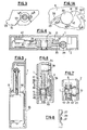
- Figs. 1 to 8 We will first refer to Figs. 1 to 8 to examine the construction of the lock according to the preferred embodiment of the invention.
- This lock firstly comprises a box 1 of rectangular shape closed by a cover 2. If the lock is used for a vehicle door, which is a preferred application, this box is pressed by its bottom against the edge of the door or optionally incorporated therein.
- the housing 1 comprises a transverse blind passage 3 with a flared inlet 4 in which is intended to penetrate a keeper 5 movable in translation relative to the housing.
- this keeper 5 which is a simple piece of metal round is fixed in the amount associated with the door fitted with the housing 1.
- the articulation pin 8 is riveted on the cover 2 as shown at 13 in FIG. 2 and positioned axially and transversely relative to the bottom of the housing 1 by positioning lugs 14a and 14b projecting from this bottom of the housing.
- the barrel of this spindle constitutes the axis of oscillation of two parallel plates 15 and 16 which are integral in rotation with one another by a spacer 17 by means of pins 18 obtained by deformation in opposite directions of this spacer and engaged in axial holes 19 provided in the respective plate 15 or 16.
- the plate 15 has a first notch 20 to be described in detail later, a second notch 21 for hooking one of the branches of a helical return spring 22 and a heel 23 forming a stop.
- the return spring 22 is engaged on the positioning lug 14a of the casing 1 (coaxial with the spindle 8) and its opposite branch bears against the positioning lug 14b which occupies an eccentric position relative to this spindle like this is shown clearly in FIG. 3.
- the bolt assembly 7 is biased by the spring 22 to rotate clockwise, considering FIG. 1 (arrow F 2 ).
- the plate 16 has a fork-shaped portion 24 which is intended to overlap the keeper 5 when the lock is locked as shown in FIG. 1.
- the operating lever 9 (Fig. 1, 6 and 7) is formed by a slightly arched plate which is rotatably mounted around the spindle 10 by one of these ends.
- This pin 10 is surrounded by a helical spring 25, one of the branches of which is hooked on a stop lug 26 of the cover 2 and the opposite branch of which is engaged in a hole 27 in the lever 9 to urge the latter in the opposite direction. clockwise (seen in Fig. 1).
- the operating lever 9 has a concave curved edge 28 opposite the plate 15 which has a curved conjugate edge 29 of convex shape in which the notch 20 is cut.
- the curved edge 29 of the lever 9 has two adjacent notches 30 and 31
- the edges 28 and 29 have an arc shape.
- the operating lever 9 On the side opposite to the plate 15, the operating lever 9 has a curved edge 32 forming a cam follower.
- the actuation assembly 11 comprises an electric drive motor 33, the output shaft of which is provided with an endless screw 34.
- the latter meshes with a toothed wheel 35 rotatably mounted around a fixed spindle 36 (Fig. 4 and 6).
- the toothed wheel 35 carries a cam ring 37, a first cam 38 of which is oriented radially in order to cooperate with the outer curved edge 32 of the operating lever 9.
- the other cam 39 is oriented axially and cooperates with the pusher 41 of a electrical contact 42.
- the locking member 12 is a roller of circular section whose radius is equal to that of the notches in a circular arc 30 and 31 provided in the operating lever 9. This is mounted between the lateral flanges of a retaining bracket 43 whose extent is such that the roller 12 is held in place in the notch 20 formed in the wafer 15 whatever the operating phase of the lock.
- the stirrup 43 is mounted oscillating on the spindle 10 and oscillates in concert with the operating lever 9.
- Fig. 1A shows by a view on a larger scale, the shape of the notch 20 formed in the edge 29 of the plate 15. If we consider the pivoting movement of the bolt assembly 7 in the direction of opening of the lock (arrow F 2 ), the notch 20 is delimited by an upstream rounded 20a forming a pusee beak for the locking member 12 and this rounded is connected to a portion of surface 20b roughly in arc of circle and concave, in turn connected to a flat sliding surface 20c which ends on a spout 20d for holding the blocking member 12.
- connection surface 20b in an arc of a circle has a radius which is less than that of the roller or locking member 12.
- the volume of the notch 20 is chosen in such a way that the roller 12 can completely s 'retract within the limits of the periphery of the plate 15 which is defined, in the region of the notch 20 by the fictitious line connecting the two sections of the curved edge 29 of the plate 15. In other words to retract , the roller 12 can slide on the flat surface 20c to be housed in the part of the notch 20 which is defined by the connection surface 20b.
- a damper 44 is housed at the bottom of the passage 3, this damper being crushed by the keeper 5 when the lock is completely locked.
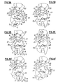
- Fig. 9A the lock is at rest in the open position (door open).
- the bolt 7 is tilted to its extreme unlocking position in which it is placed under the action of the spring 22, the position being fixed by the heel 23 which, serving as a stop abuts against the rear edge of the operating lever 9.
- the conjugate edges 28 and 29 are offset with respect to each other, the notch 20 being located opposite the end of the edge 28 which is distant from the articulation pin 10.
- the member blocking or roller 12 is placed in the “upstream” part of the notch 20 seen in the direction F 2 of bias towards the opening of the bolt 7.
- the cam 38 is in contact with the outer convex edge 32 of the operating lever 9
- the electric motor is de-energized.
- the keeper 5 comes to meet the forked part of the plate 16 of the bolt 7 by exerting a force f 1 on it.
- This force acts against the spring 22 and if it is sufficient, initiates the rotation movement of the bolt 7 in the opposite direction to that of the needles of a watch, the spring 22 being progressively tensioned (arrow Fra; Fig. 9B ).
- the roller 12 is first of all simply transported with the bolt 7 by following the edge 28 of the maneuvering lever. The movement of the keeper continuing, there comes a time when the roller 12 is located opposite the notch 31 hereinafter called "first notch".
- the lock will be locked in a closing position called "first notch” by a slight backward movement of the bolt in the opposite direction (arrow Fg-b) under the impulse of the spring 22 which can possibly be assisted by the elastic force generated by the damper 44 assumed to be slightly compressed at this time by the keeper.
- Fig. 9B therefore shows the lock in this particular “first notch” locking condition.
- the roller 12 To move from this position to the next ("second notch"), the roller 12 should be transferred from the position of FIG. 9B to that of FIG. 9C.
- the keeper again exerting a force on the bolt 7, the latter continues its movement in the direction Fra which causes the planar surface 20c (Fig. 1A) to move away from the concave edge 28 of the operating lever 9.
- the available volume for the roller 12 increases and the latter can therefore come out of the notch 31 in which it was previously engaged.
- the bolt still continuing its movement, it pushes the roller 12 forward so that the latter crosses the ridge between the two notches 30 and 31.
- the motor 33 To unlock the lock, the motor 33 must be excited to cause the gear 35 to rotate in the direction of arrow F 4 .
- the cam 38 leaves the convex edge 32 of the operating lever 9 which makes it rotate about its axis in the direction of the arrow F 5 while being driven by the force of the spring 25. This results in an enlargement of the volume available to the roller 12 from which the notch is released.
- the bolt 7 is immediately brought back on the one hand by the spring 22 and on the other hand (if necessary) by the keeper which is pushed back by the damper 44 and possibly the door seals.
- the roller 12 is then caused to fall by gravity into the bottom of the notch 20 to find itself again in its retracted position. If the lock occupies a different position, this movement can be caused by a spring similar to spring 55 (then absent) but acting in the opposite direction. However, in any event and regardless of the position of the lock, the roller 12 is returned to its retracted position as soon as the lever 9 has returned to its initial position, which occurs very quickly. after a complete revolution of the cam 38, that is to say before the bolt has found its own (Fig. 9F).
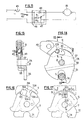
- Fig. 11 shows an electrical diagram of an example of a motor control circuit 33.
- the lock can be controlled by a simple push button 45 which is mounted between one of the poles of a source supply and an assembly 46 for instantaneous stop of the motor 33.
- the push-button 45 is mounted in parallel on the switch 42 acting as a holding contact.
- the assembly 46 comprises a short-circuit transistor 47 of the armature of the motor 33. Its collector is connected with one of the motor terminals to the opposite pole of the power source, while by its emitter is connected between the cathode of a diode 48 and the opposite terminal of the motor armature.
- the base of the transistor is connected by a resistor R1 to the anode of the diode 48 and to the parallel mounting of the push button 45 and of the switch 42.
- a resistor R2 connects the collector of the transistor 47 to the anode of the diode 48.
- the opening of the lock requires a force which is none other than the friction force between the cam 38 and the convex outer surface 32 of the lever.
- the roller 12 does not have to cross any obstacle either during locking or during unlocking.
- the electric motor 33 can therefore be of very low power allowing it to be inserted into the lock housing.
- the roller 12 is under stress only in the locking position of the lock which is static. During its movements, it moves without being pressed against any surface which reduces wear to a minimum value. It is the same with the profiled surfaces of the bolt on the one hand and of the operating lever on the other hand.
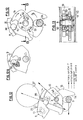
- Figs. 12 and 13 show a variant of the lock in which the two plates 15 and 16 are integral with one another with the possibility of a slight angular movement. To this end, they are connected to each other by a spacer 49 which by a first deformation 50 is rigidly fixed to the plate 16, while a second deformation 51 is engaged with a slight play in a slot 52 in bean shape provided in the other plate 15. The spacer is mounted to oscillate on the spindle 8.
- a helical spring 53 is mounted around the spindle while being hooked by its ends respectively in the plates 15 and 16 in order to urge them around the spindle 8 in the direction of the arrows F 6 .
- Fig. 12A shows another variant in which there is provided a roller 12A with a circular groove 54 into which a spring 55 of wire can penetrate urging it towards the bottom of the notch 20.
- This spring 55 is fixed in the plate 16 extending roughly perpendicular to the flat surface - 20c of the notch 20, and is tensioned when the roller 12A is in its "second notch" locking position.
- Figs. 14 and 15 illustrate another variant in which the lock according to the invention comprises a bolt 7A produced in one piece from a single plate with two plates 56 and 57 arranged in parallel and joined together by a joining part 58 perpendicular to these trays.
- the assembly is mounted oscillating on the spindle 8 which crosses the plate 56.
- the latter has the forked portion intended to overlap the keeper 5 for locking, while the plate 57 comprises the notch 20.
- the variant also includes a blocking member 12B which is here formed by a spherical ball.
- Fig. 16 shows another variant in which the lock comprises a blocking member 12 constituted by a block in the form of a rectangular parallelepiped.
- the operating lever 9 has notches 30A and 31A in the form of a V, while the notch 20A is delimited by two mutually perpendicular surfaces 20A-a and 20A-b.
- the blocking member 12D is in the form of a shouldered cylindrical pin which is mounted in a housing 20B provided in the plate 16. This pin is biased towards the outside by a spring 59.
- the operating lever 9 has a single notch 60 mounted, preferably mobile in translation instead of being pivoting (see arrows F 7 ).
Landscapes
- Lock And Its Accessories (AREA)
Applications Claiming Priority (2)
| Application Number | Priority Date | Filing Date | Title |
|---|---|---|---|
| FR8123916A FR2518620A1 (fr) | 1981-12-22 | 1981-12-22 | Serrure a pene pivotant, notamment pour vehicule automobile |
| FR8123916 | 1981-12-22 |
Publications (2)
| Publication Number | Publication Date |
|---|---|
| EP0082761A1 EP0082761A1 (fr) | 1983-06-29 |
| EP0082761B1 true EP0082761B1 (fr) | 1986-03-12 |
Family
ID=9265255
Family Applications (1)
| Application Number | Title | Priority Date | Filing Date |
|---|---|---|---|
| EP82402273A Expired EP0082761B1 (fr) | 1981-12-22 | 1982-12-13 | Serrure, notamment pour véhicule automobile |
Country Status (6)
| Country | Link |
|---|---|
| US (1) | US4569544A (enExample) |
| EP (1) | EP0082761B1 (enExample) |
| DE (1) | DE3269903D1 (enExample) |
| ES (1) | ES284384Y (enExample) |
| FR (1) | FR2518620A1 (enExample) |
| YU (1) | YU46129B (enExample) |
Cited By (1)
| Publication number | Priority date | Publication date | Assignee | Title |
|---|---|---|---|---|
| CN106468116A (zh) * | 2015-08-21 | 2017-03-01 | 麦格纳覆盖件有限公司 | 包括有助减少释放耗力的支承件的汽车闩锁 |
Families Citing this family (51)
| Publication number | Priority date | Publication date | Assignee | Title |
|---|---|---|---|---|
| FR2539174B1 (fr) * | 1983-01-06 | 1987-05-22 | Peugeot Aciers Et Outillage | Serrure, notamment pour portiere de vehicule |
| US4652027A (en) * | 1984-07-16 | 1987-03-24 | Quantz Norman G | Electrically actuated lock mechanism |
| FR2586744B1 (fr) * | 1985-09-05 | 1987-12-04 | Mecanismes Comp Ind De | Serrure a ouverture et fermeture electriques, notamment pour portieres de vehicules automobiles |
| DE3531931A1 (de) * | 1985-09-07 | 1987-03-19 | Ymos Ag Ind Produkte | Schliesseinrichtung fuer kraftfahrzeuge |
| US4703961A (en) * | 1986-09-12 | 1987-11-03 | The Eastern Company | Rotary latch with internal bumper block |
| US4763936A (en) * | 1986-10-20 | 1988-08-16 | General Motors Corporation | Power operated door latch |
| US4968074A (en) * | 1987-12-22 | 1990-11-06 | Ohi Seisakusho Co., Ltd. | Automatic door latching system |
| CA1320238C (en) * | 1988-03-14 | 1993-07-13 | Shinjiro Yamada | Door lock device for vehicle |
| US5169186A (en) * | 1988-07-21 | 1992-12-08 | Aisin Seiki Kabushiki Kaisha | Door lock device |
| JP2707637B2 (ja) * | 1988-09-30 | 1998-02-04 | アイシン精機株式会社 | ラゲージドアロック装置 |
| JP2658272B2 (ja) * | 1988-09-30 | 1997-09-30 | アイシン精機株式会社 | ドア閉鎖装置 |
| US4986576A (en) * | 1988-12-27 | 1991-01-22 | The Hartwell Corporation | Locking door latch |
| US5007261A (en) * | 1989-07-20 | 1991-04-16 | Quantz Norman G | Electrically actuated lock mechanism with electrical failure protection |
| DE3927445C2 (de) * | 1989-08-19 | 2000-12-07 | Kiekert Ag | Kraftfahrzeug-Türverschluß |
| JP2556789B2 (ja) * | 1991-03-29 | 1996-11-20 | 株式会社大井製作所 | 自動車用ドアロックの施解錠操作装置 |
| DE4205269C1 (enExample) * | 1992-02-21 | 1993-05-06 | Mercedes-Benz Aktiengesellschaft, 7000 Stuttgart, De | |
| JP2739677B2 (ja) * | 1993-12-13 | 1998-04-15 | 三井金属鉱業株式会社 | 車両用扉のロック装置 |
| US5667263A (en) * | 1994-09-01 | 1997-09-16 | Kiekert Aktiengesellshaft | Power-actuated motor-vehicle door latch |
| DE29511451U1 (de) * | 1995-01-10 | 1995-09-07 | Bomoro Bocklenberg & Motte Gmbh & Co Kg, 42369 Wuppertal | Kraftfahrzeug-Türschloß mit rotorischer Zentralverriegelung |
| US5639130A (en) * | 1995-05-31 | 1997-06-17 | General Motors Corporation | Rotary door cinching mechanism with manual override |
| US6279361B1 (en) * | 1995-12-20 | 2001-08-28 | Vdo Adolf Schindling Ag | Lock in particular for motor vehicle doors |
| US5613716A (en) * | 1996-01-25 | 1997-03-25 | General Motors Corporation | Electronic vehicle door unlatch control |
| CA2295072C (en) * | 1997-08-21 | 2006-11-14 | Atoma International Corp. | Vehicle door latch with reduced release effort |
| AU7922400A (en) * | 1999-10-29 | 2001-05-14 | Kiekert Aktiengesellschaft | Locking system for the door of a motor vehicle |
| DE19955883A1 (de) * | 1999-11-20 | 2001-05-31 | Kiekert Ag | Kraftfahrzeugtürverschluss |
| DE10009391A1 (de) * | 2000-02-29 | 2001-09-13 | Bosch Gmbh Robert | Kraftfahrzeug-Türschloss |
| DE10028176A1 (de) * | 2000-06-09 | 2001-12-13 | Michael Dorn | Selbstverriegelndes Schloß und mit diesem ausgestattetes Schließsystem |
| US20040207214A1 (en) * | 2003-04-16 | 2004-10-21 | Yi-An Lin | Electronic door lock |
| US7261334B2 (en) * | 2003-06-24 | 2007-08-28 | Intier Automotive Closures Inc. | Power release actuator |
| CZ301333B6 (cs) * | 2003-09-10 | 2010-01-20 | Brano A.S. | Automobilový zámek, zejména zámek okna pátých dverí, s elektrickým odjištováním |
| WO2006028804A2 (en) * | 2004-09-01 | 2006-03-16 | Southco, Inc. | Latch with dual rotary pawls |
| EP1846904B1 (en) | 2005-02-12 | 2015-10-14 | Southco, Inc. | Magnetic latch mechanism |
| KR20080015428A (ko) * | 2005-05-08 | 2008-02-19 | 사우스코 인코포레이티드 | 자석식 걸쇠장치 |
| US7416229B2 (en) * | 2005-07-06 | 2008-08-26 | Brose Schliesssysteme Gmbh & Co. Kg | Motor vehicle lock |
| FR2905971B1 (fr) * | 2006-09-15 | 2008-10-24 | Peugeot Citroen Automobiles Sa | Systeme d'assistance a l'ouverture d'une serrure d'ouvrant de vehicule automobile |
| CN101600844B (zh) * | 2006-11-20 | 2012-07-11 | 索斯科公司 | 电动机械式旋转掣子闩锁 |
| FR2920805B1 (fr) * | 2007-09-11 | 2009-11-06 | Peugeot Citroen Automobiles Sa | Systeme d'assistance a l'ouverture d'une serrure. |
| FR2924736B1 (fr) * | 2007-12-11 | 2013-05-31 | Valeo Securite Habitacle | Procede de fabrication d'une serrure de porte de vehicule automobile. |
| DE102008031206A1 (de) * | 2008-07-03 | 2010-01-14 | Kiekert Ag | Dämpferelement für ein Kraftfahrzeugschloss |
| FR2953549A1 (fr) * | 2009-12-08 | 2011-06-10 | Valeo Securite Habitacle | Serrure d'ouvrant de vehicule muni d'un levier de commande |
| CN103080452B (zh) * | 2010-03-16 | 2016-02-10 | 索斯科公司 | 适于将闭合构件紧固在预定位置的闩锁和操作闩锁的方法 |
| US8348309B2 (en) * | 2010-11-22 | 2013-01-08 | Ford Global Technologies, Llc | Energy absorbing bumper for latch closing sound quality |
| CA2798465C (fr) * | 2011-12-09 | 2015-06-30 | Messier-Bugatti-Dowty | Boitier d'accrochage a actionneur a came d'encombrement reduit |
| WO2017201190A1 (en) * | 2016-05-18 | 2017-11-23 | Shanghai Yanfeng Jinqiao Automotive Trim Systems Co. Ltd | Console assembly for vehicle interior |
| US11072948B2 (en) * | 2016-12-14 | 2021-07-27 | Magna Closures S.P.A. | Smart latch |
| CN114673412B (zh) * | 2018-02-08 | 2023-08-29 | 麦格纳覆盖件有限公司 | 具有闩锁机构的闭合闩锁组件及其操作方法 |
| DE102018115048A1 (de) * | 2018-06-22 | 2019-12-24 | Kiekert Ag | Kraftfahrzeugschloss |
| DE102018120238A1 (de) * | 2018-08-20 | 2020-02-20 | Kiekert Ag | Kraftfahrzeugschloss |
| DE102018121509A1 (de) * | 2018-09-04 | 2020-03-05 | Kiekert Ag | Kraftfahrzeugschloss |
| DE102019123837A1 (de) * | 2018-10-22 | 2020-04-23 | Kiekert Aktiengesellschaft | Kraftfahrzeugschloss |
| US11572723B2 (en) | 2019-02-27 | 2023-02-07 | Shanghai Yanfeng Jinqiao Automotive Triim Systems Co. Ltd. | Vehicle interior component |
Family Cites Families (11)
| Publication number | Priority date | Publication date | Assignee | Title |
|---|---|---|---|---|
| US2864636A (en) * | 1956-02-27 | 1958-12-16 | Ferro Stamping Co | Wedge type lock |
| US3354583A (en) * | 1965-09-27 | 1967-11-28 | Gen Motors Corp | Refrigerator door opener |
| FR93350E (fr) * | 1966-12-16 | 1969-03-14 | Mecanismes Comp Ind De | Serrures a bille ou a galet. |
| US3547476A (en) * | 1967-01-24 | 1970-12-15 | Bomoro Bocklenberg & Motte Kg | Turn latch lock for motor vehicle doors |
| US3785186A (en) * | 1972-11-30 | 1974-01-15 | Gen Motors Corp | Closure latch arrangement |
| IT1115555B (it) * | 1977-09-12 | 1986-02-03 | Mecanismes Comp Ind De | Serratura particolarmente per porte di autoveicoli |
| US4177656A (en) * | 1978-03-02 | 1979-12-11 | The Eastern Company | Cabinet lock |
| US4270783A (en) * | 1979-01-24 | 1981-06-02 | Lake Center Industries | Door lock actuator |
| FR2472651A1 (fr) * | 1979-12-28 | 1981-07-03 | Cerdan Jacques | Perfectionnement aux serrures de portiere pour vehicules automobiles |
| FR2501766A1 (fr) * | 1981-03-10 | 1982-09-17 | Renault | Dispositif de verrouillage electrique, notamment d'un capot de vehicule automobile |
| FR2528097A2 (fr) * | 1982-06-02 | 1983-12-09 | Peugeot Aciers Et Outillage | Serrure a pene pivotant entraine, notamment pour vehicule automobile |
-
1981
- 1981-12-22 FR FR8123916A patent/FR2518620A1/fr active Granted
-
1982
- 1982-12-13 DE DE8282402273T patent/DE3269903D1/de not_active Expired
- 1982-12-13 EP EP82402273A patent/EP0082761B1/fr not_active Expired
- 1982-12-17 US US06/450,842 patent/US4569544A/en not_active Expired - Fee Related
- 1982-12-20 YU YU281682A patent/YU46129B/sh unknown
- 1982-12-20 ES ES1982284384U patent/ES284384Y/es not_active Expired
Cited By (2)
| Publication number | Priority date | Publication date | Assignee | Title |
|---|---|---|---|---|
| CN106468116A (zh) * | 2015-08-21 | 2017-03-01 | 麦格纳覆盖件有限公司 | 包括有助减少释放耗力的支承件的汽车闩锁 |
| CN106468116B (zh) * | 2015-08-21 | 2022-10-28 | 麦格纳覆盖件有限公司 | 包括有助减少释放耗力的支承件的汽车闩锁 |
Also Published As
| Publication number | Publication date |
|---|---|
| US4569544A (en) | 1986-02-11 |
| ES284384U (es) | 1986-01-01 |
| YU46129B (sh) | 1993-05-28 |
| EP0082761A1 (fr) | 1983-06-29 |
| DE3269903D1 (en) | 1986-04-17 |
| YU281682A (en) | 1985-03-20 |
| FR2518620A1 (fr) | 1983-06-24 |
| ES284384Y (es) | 1986-08-01 |
| FR2518620B1 (enExample) | 1984-02-24 |
Similar Documents
| Publication | Publication Date | Title |
|---|---|---|
| EP0082761B1 (fr) | Serrure, notamment pour véhicule automobile | |
| EP0059658B1 (fr) | Serrure, notamment pour portière de véhicule automobile | |
| EP3511496B1 (fr) | Serrure a trois positions pour vehicule automobile | |
| EP0113630A1 (fr) | Serrure, notamment pour portière de véhicule | |
| FR2785638A1 (fr) | Serrure de porte a condamnation/decondamnation electrique exterieure et/ou interieur pour vehicule automobile | |
| EP0978609A1 (fr) | Serrure de porte à assistance électrique | |
| EP0274287A1 (fr) | Serrure, notamment pour porte de véhicule automobile | |
| EP0812972A2 (fr) | Serrure électrique pour ouvrant de véhicule automobile | |
| FR2813631A1 (fr) | Vehicule automobile avec une porte battante et une porte coulissante independantes l'une de l'autre | |
| FR2641312A1 (fr) | Mecanisme pour portes tournantes basculantes | |
| EP0159238A1 (fr) | Dispositif électromécanique de commande de l'ouverture d'une serrure et serrure de portière de véhicule automobile comportant un tel dispositif | |
| EP0292361B1 (fr) | Serrure comportant un mécanisme de déverrouillage à fonctionnement électrique | |
| EP0153231A1 (fr) | Serrure pour portière de véhicule automobile | |
| EP2115247B1 (fr) | Serrure électrique perfectionnée pour ouvrant de véhicule automobile | |
| EP0095988B1 (fr) | Serrure de portière, notamment pour véhicule automobile | |
| EP0102263B1 (fr) | Serrure à commande électrique pour portière de véhicule automobile | |
| EP0095983B1 (fr) | Serrure, notamment pour véhicule automobile | |
| FR2567949A1 (fr) | Dispositif de commande de l'ouverture d'une serrure de portiere de vehicule automobile | |
| EP0243214B1 (fr) | Dispositif de blocage utilisable comme anti-vol pour serrure électrique de véhicule automobile et serrure correspondante | |
| WO1989003922A1 (fr) | Dispositif de commande d'ouverture temporisee d'une serrure de securite | |
| EP0230808B1 (fr) | Actionneur de condamnation d'une serrure de porte de véhicule automobile | |
| FR2789718A1 (fr) | Serrure a condamnation enfant, pour ouvrant de vehicule automobile | |
| EP0433104B1 (fr) | Mécanisme de débrayage de l'organe de verrouillage manuel associé à une serrure de portière de véhicule automobile et serrure le comportant | |
| FR2944826A1 (fr) | Serrure a pene coulant verrouillable par genouillere | |
| FR2796488A1 (fr) | Dispositif pour activer et desactiver des appareils de commutation agences sous forme de bloc |
Legal Events
| Date | Code | Title | Description |
|---|---|---|---|
| PUAI | Public reference made under article 153(3) epc to a published international application that has entered the european phase |
Free format text: ORIGINAL CODE: 0009012 |
|
| AK | Designated contracting states |
Designated state(s): BE DE GB IT SE |
|
| 17P | Request for examination filed |
Effective date: 19830630 |
|
| ITF | It: translation for a ep patent filed | ||
| GRAA | (expected) grant |
Free format text: ORIGINAL CODE: 0009210 |
|
| AK | Designated contracting states |
Kind code of ref document: B1 Designated state(s): BE DE GB IT SE |
|
| PG25 | Lapsed in a contracting state [announced via postgrant information from national office to epo] |
Ref country code: SE Effective date: 19860331 |
|
| REF | Corresponds to: |
Ref document number: 3269903 Country of ref document: DE Date of ref document: 19860417 |
|
| PG25 | Lapsed in a contracting state [announced via postgrant information from national office to epo] |
Ref country code: BE Effective date: 19861231 |
|
| PLBE | No opposition filed within time limit |
Free format text: ORIGINAL CODE: 0009261 |
|
| STAA | Information on the status of an ep patent application or granted ep patent |
Free format text: STATUS: NO OPPOSITION FILED WITHIN TIME LIMIT |
|
| 26N | No opposition filed | ||
| BERE | Be: lapsed |
Owner name: ACIERS ET OUTILLAGE PEUGEOT Effective date: 19861231 |
|
| PGFP | Annual fee paid to national office [announced via postgrant information from national office to epo] |
Ref country code: DE Payment date: 19911025 Year of fee payment: 10 |
|
| PGFP | Annual fee paid to national office [announced via postgrant information from national office to epo] |
Ref country code: GB Payment date: 19911206 Year of fee payment: 10 |
|
| ITTA | It: last paid annual fee | ||
| PG25 | Lapsed in a contracting state [announced via postgrant information from national office to epo] |
Ref country code: GB Effective date: 19921213 |
|
| ITPR | It: changes in ownership of a european patent |
Owner name: CAMBIO RAGIONE SOCIALE;ECIA - EQUIPEMENTS ET COMPO |
|
| GBPC | Gb: european patent ceased through non-payment of renewal fee |
Effective date: 19921213 |
|
| PG25 | Lapsed in a contracting state [announced via postgrant information from national office to epo] |
Ref country code: DE Effective date: 19930901 |