EP0081676A1 - Alternateur asynchrone ayant les aimants permanents disposés sur le rotor - Google Patents
Alternateur asynchrone ayant les aimants permanents disposés sur le rotor Download PDFInfo
- Publication number
- EP0081676A1 EP0081676A1 EP82110323A EP82110323A EP0081676A1 EP 0081676 A1 EP0081676 A1 EP 0081676A1 EP 82110323 A EP82110323 A EP 82110323A EP 82110323 A EP82110323 A EP 82110323A EP 0081676 A1 EP0081676 A1 EP 0081676A1
- Authority
- EP
- European Patent Office
- Prior art keywords
- rotor
- permanent magnets
- asynchronous generator
- generator according
- magnets
- Prior art date
- Legal status (The legal status is an assumption and is not a legal conclusion. Google has not performed a legal analysis and makes no representation as to the accuracy of the status listed.)
- Ceased
Links
Images
Classifications
-
- H—ELECTRICITY
- H02—GENERATION; CONVERSION OR DISTRIBUTION OF ELECTRIC POWER
- H02K—DYNAMO-ELECTRIC MACHINES
- H02K1/00—Details of the magnetic circuit
- H02K1/06—Details of the magnetic circuit characterised by the shape, form or construction
- H02K1/22—Rotating parts of the magnetic circuit
- H02K1/27—Rotor cores with permanent magnets
- H02K1/2706—Inner rotors
- H02K1/272—Inner rotors the magnetisation axis of the magnets being perpendicular to the rotor axis
- H02K1/274—Inner rotors the magnetisation axis of the magnets being perpendicular to the rotor axis the rotor consisting of two or more circumferentially positioned magnets
- H02K1/2753—Inner rotors the magnetisation axis of the magnets being perpendicular to the rotor axis the rotor consisting of two or more circumferentially positioned magnets the rotor consisting of magnets or groups of magnets arranged with alternating polarity
- H02K1/278—Surface mounted magnets; Inset magnets
-
- H—ELECTRICITY
- H02—GENERATION; CONVERSION OR DISTRIBUTION OF ELECTRIC POWER
- H02K—DYNAMO-ELECTRIC MACHINES
- H02K17/00—Asynchronous induction motors; Asynchronous induction generators
- H02K17/42—Asynchronous induction generators
-
- H—ELECTRICITY
- H02—GENERATION; CONVERSION OR DISTRIBUTION OF ELECTRIC POWER
- H02K—DYNAMO-ELECTRIC MACHINES
- H02K2201/00—Specific aspects not provided for in the other groups of this subclass relating to the magnetic circuits
- H02K2201/06—Magnetic cores, or permanent magnets characterised by their skew
Definitions
- the invention relates to an asynchronous generator with permanent magnets arranged on the rotor. It has long been known that an asynchronous motor becomes an asynchronous generator when capacitors are connected in parallel with the windings. These capacitors form an oscillating circuit. If the motor is rotated beyond the synchronous speed, the circuit is excited and the oscillating current causes the magnetization. In order for excitement to occur, the presence of remanence in the runner is necessary. Disadvantages: If the generator is short-circuited, it excites itself and the remanence is destroyed. A further arousal is no longer possible. The remanence is destroyed even if the generator is turned up very quickly. Remedial measures have been taken to send a direct current surge from an accumulator through the stator or to let the generator run briefly as a motor. Even with these measures, there is no absolute certainty that the generator is excited.
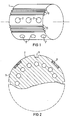
- the current technology in the manufacture of a rotor is that stamped sheets with circular recesses close to the circumference according to FIG. 1 are placed on top of each other so that cylindrical cavities are created.
- both the cylindrical cavities are filled with aluminum and the short-circuit rings are produced in a single operation. It has also already become possible to produce magnetic materials with an extremely high coercive force.
- the invention has set itself the task of taking this new state of the art into account in a manner corresponding to the original tasks, but essentially different in its implementation, and to develop an asynchronous generator which has the advantages of greatest simplicity. And thus cost savings with optimal efficiency, as well absolute synchronization security at lowest speeds results.
- the invention consists in that permanent magnets with radial directions opposite to the rotor and in the circumferential direction of the rotor successively opposite directions of magnetization are inserted in the lateral surface of the rotor, and that at least one groove is provided between two permanent magnets.
- Narrow grooves with shallow depth parallel to or oblique to the rotor axis are advantageously milled with sharp edges with a rectangular cross section into the jacket of the rotor from one end face to the other.
- Magnets have turned out to be lathanide nickel magnets or cobalt platinum magnets, which have a high coercive force.
- the circumferential distribution and polarity of the rotor magnets correspond to the pole pitch of the generator, and at least one assigned rotor magnet with at least one groove is provided for each generator pole.
- the mode of operation of the invention can be seen directly from FIG. 1.
- the rotor 1 is equipped on its outer surface with magnetic plates 2, 2 'fixed in recesses. If there were no grooves, the field would largely close in the rotor itself.
- the mode of operation of the grooves is shown in FIG. 2.
- the line of force of the magnetic field is interrupted by the grooves 3 milled into the lateral surface, so that the field lines emerge from the rotor due to the low permeability of the iron-free spaces 3 and can thus enforce the stator winding in the sense of an induction that promotes self-excitation.
- the solution according to the invention especially in systems with rapidly changing rotational speeds, for example in wind turbines, can achieve reliable self-excitation even when the vehicle is temporarily at a standstill or, conversely, in the event of sudden gusts of wind by connecting capacitors, the rotational speed within this case too the areas given by the resonance conditions of the system.
- Wind tunnel tests have shown that a wind converter designed according to the invention practically does not change its speed or even gets out of step even in a 150 km storm.
- the solution according to the invention therefore allows wind turbines to be built which no longer have a gearbox, because synchronization occurs even at low revs and no longer have variable pitch propellers, because by connecting sufficiently large capacitors, a low number of revolutions can be forced with perfect synchronization.
- the compensation currents or fields occurring during the braking or starting processes are not able to demagnetize the magnetic materials used, which are essential for the invention, since their magnetization loop in any case ensures the required remanence magnetization of the rotor and thus the self-excitation .
- the rotor magnets 2, 2 ' are to be arranged in such a way that their circumferential distribution and polarity correspond to the pole pitch of the generator, with several rotor magnets per generator pole 2, 2 'can be provided.
- a rotor which according to the invention is only equipped with magnets, can only be partially synchronized, a rotor can only be provided with grooves, and can almost not be synchronized. If the machine is short-circuited, it will of course be de-energized, but if the short-circuit is eliminated, synchronization will take place in a few seconds.
Landscapes
- Engineering & Computer Science (AREA)
- Power Engineering (AREA)
- Permanent Magnet Type Synchronous Machine (AREA)
- Permanent Field Magnets Of Synchronous Machinery (AREA)
Applications Claiming Priority (4)
| Application Number | Priority Date | Filing Date | Title |
|---|---|---|---|
| AT5014/81 | 1981-11-20 | ||
| AT501481A ATA501481A (de) | 1981-11-20 | 1981-11-20 | Asynchrongenerator mit am laeufer angeordneten permanentmagneten |
| AT5085/81 | 1981-11-26 | ||
| AT0508581A AT370926B (de) | 1981-11-26 | 1981-11-26 | Asynchrongenerator mit am laeufer angeordneten permanentmagneten |
Publications (1)
| Publication Number | Publication Date |
|---|---|
| EP0081676A1 true EP0081676A1 (fr) | 1983-06-22 |
Family
ID=25601766
Family Applications (1)
| Application Number | Title | Priority Date | Filing Date |
|---|---|---|---|
| EP82110323A Ceased EP0081676A1 (fr) | 1981-11-20 | 1982-11-09 | Alternateur asynchrone ayant les aimants permanents disposés sur le rotor |
Country Status (5)
| Country | Link |
|---|---|
| EP (1) | EP0081676A1 (fr) |
| DK (1) | DK512882A (fr) |
| ES (1) | ES517520A0 (fr) |
| GR (1) | GR77038B (fr) |
| PT (1) | PT75871B (fr) |
Cited By (1)
| Publication number | Priority date | Publication date | Assignee | Title |
|---|---|---|---|---|
| CN104113152A (zh) * | 2013-07-10 | 2014-10-22 | 王贤长 | 一种三相异步电动机的永磁转子 |
Citations (3)
| Publication number | Priority date | Publication date | Assignee | Title |
|---|---|---|---|---|
| US2643350A (en) * | 1952-06-28 | 1953-06-23 | Gen Electric | Dynamoelectric machine magnetic core member |
| AT180329B (de) * | 1952-08-16 | 1954-11-25 | Friedrich Kubik | Asynchrongenerator |
| US3731125A (en) * | 1970-06-13 | 1973-05-01 | Citizen Watch Co Ltd | Pulse motor for time piece |
-
1982
- 1982-11-09 EP EP82110323A patent/EP0081676A1/fr not_active Ceased
- 1982-11-18 GR GR69845A patent/GR77038B/el unknown
- 1982-11-18 PT PT75871A patent/PT75871B/pt unknown
- 1982-11-18 DK DK512882A patent/DK512882A/da not_active Application Discontinuation
- 1982-11-19 ES ES517520A patent/ES517520A0/es active Granted
Patent Citations (3)
| Publication number | Priority date | Publication date | Assignee | Title |
|---|---|---|---|---|
| US2643350A (en) * | 1952-06-28 | 1953-06-23 | Gen Electric | Dynamoelectric machine magnetic core member |
| AT180329B (de) * | 1952-08-16 | 1954-11-25 | Friedrich Kubik | Asynchrongenerator |
| US3731125A (en) * | 1970-06-13 | 1973-05-01 | Citizen Watch Co Ltd | Pulse motor for time piece |
Cited By (1)
| Publication number | Priority date | Publication date | Assignee | Title |
|---|---|---|---|---|
| CN104113152A (zh) * | 2013-07-10 | 2014-10-22 | 王贤长 | 一种三相异步电动机的永磁转子 |
Also Published As
| Publication number | Publication date |
|---|---|
| PT75871B (de) | 1985-02-27 |
| ES8309038A1 (es) | 1983-10-01 |
| GR77038B (fr) | 1984-09-04 |
| ES517520A0 (es) | 1983-10-01 |
| PT75871A (de) | 1982-12-01 |
| DK512882A (da) | 1983-05-21 |
Similar Documents
| Publication | Publication Date | Title |
|---|---|---|
| DE2611506C2 (de) | Verfahren zur Herstellung eines zylinderförmigen Magnetkerns mit einer Magnetspulenanordnung | |
| DE2457783C2 (de) | Magnetische Lagerung | |
| DE3440193A1 (de) | Laeufer mit permanent-magneten | |
| DE3135924A1 (de) | Dynamoelektrische maschine mit permanentmagnetrotor | |
| DE3808190A1 (de) | Verfahren zum herstellen von wicklungen fuer luftspalt-motoren | |
| DE102014101330A1 (de) | Maschine mit innenliegenden Permanentmagneten | |
| EP1166423B1 (fr) | Rotor multipolaire a aimants permanents pour machine tournante electrique et procede de fabrication associe | |
| DE1230486B (de) | Elektrische Maschine, die mit zwei beiderseits des Rotors angeordneten Magneten versehen ist | |
| DE1763613A1 (de) | Verfahren zur Montage rotierender elektrischer Maschinen | |
| DE2142466A1 (de) | Dauermagneterregte elektrische maschine | |
| DE2331801C2 (de) | Synchronmaschine | |
| DE1513856A1 (de) | Wechselstromgenerator | |
| EP0081676A1 (fr) | Alternateur asynchrone ayant les aimants permanents disposés sur le rotor | |
| DE1488702B2 (de) | Synchronmaschine mit gegensinnig erregten Erregerwicklungen und einem wicklungslosen Läufer | |
| DE3819341A1 (de) | Wechselstromgenerator fuer kraftfahrzeuge | |
| DE1763858C2 (de) | Elektrische Maschine | |
| DE102017127611A1 (de) | Synchron-Reluktanzmotor mit durch Permanentmagnete gesättigtem magnetischen Nebenschlusspfad | |
| DE2331951A1 (de) | Verfahren zum herstellen magnetomotorischer vorrichtungen und dabei zu verwendende polschuh- und magnetbaugruppe | |
| AT370926B (de) | Asynchrongenerator mit am laeufer angeordneten permanentmagneten | |
| DE1927795A1 (de) | Dynamo-elektrische Maschine mit einem permanent-magnetischen Stator | |
| DE2430585C3 (de) | Selbstanlaufender Einphasensynchronmotor | |
| DE1932641A1 (de) | Schrittschaltmotor | |
| DE2822830A1 (de) | Schrittmotor | |
| DE1488053A1 (de) | Elektrische Maschine | |
| DE2816671A1 (de) | Elektrischer generator |
Legal Events
| Date | Code | Title | Description |
|---|---|---|---|
| PUAI | Public reference made under article 153(3) epc to a published international application that has entered the european phase |
Free format text: ORIGINAL CODE: 0009012 |
|
| AK | Designated contracting states |
Designated state(s): AT BE CH DE FR GB IT LI NL SE |
|
| 17P | Request for examination filed |
Effective date: 19830727 |
|
| STAA | Information on the status of an ep patent application or granted ep patent |
Free format text: STATUS: THE APPLICATION HAS BEEN REFUSED |
|
| 18R | Application refused |
Effective date: 19851028 |
|
| RIN1 | Information on inventor provided before grant (corrected) |
Inventor name: DIE ERFINDER HABEN AUF IHRE NENNUNG VERZICHTET. |