EP0081667A1 - Tuyaux posable sans compensateurs pour système de chauffage à grande distance - Google Patents
Tuyaux posable sans compensateurs pour système de chauffage à grande distance Download PDFInfo
- Publication number
- EP0081667A1 EP0081667A1 EP82110149A EP82110149A EP0081667A1 EP 0081667 A1 EP0081667 A1 EP 0081667A1 EP 82110149 A EP82110149 A EP 82110149A EP 82110149 A EP82110149 A EP 82110149A EP 0081667 A1 EP0081667 A1 EP 0081667A1
- Authority
- EP
- European Patent Office
- Prior art keywords
- pipe
- medium pipe
- medium
- district heating
- abutment
- Prior art date
- Legal status (The legal status is an assumption and is not a legal conclusion. Google has not performed a legal analysis and makes no representation as to the accuracy of the status listed.)
- Granted
Links
Images


Classifications
-
- F—MECHANICAL ENGINEERING; LIGHTING; HEATING; WEAPONS; BLASTING
- F16—ENGINEERING ELEMENTS AND UNITS; GENERAL MEASURES FOR PRODUCING AND MAINTAINING EFFECTIVE FUNCTIONING OF MACHINES OR INSTALLATIONS; THERMAL INSULATION IN GENERAL
- F16L—PIPES; JOINTS OR FITTINGS FOR PIPES; SUPPORTS FOR PIPES, CABLES OR PROTECTIVE TUBING; MEANS FOR THERMAL INSULATION IN GENERAL
- F16L59/00—Thermal insulation in general
- F16L59/14—Arrangements for the insulation of pipes or pipe systems
- F16L59/16—Arrangements specially adapted to local requirements at flanges, junctions, valves or the like
- F16L59/18—Arrangements specially adapted to local requirements at flanges, junctions, valves or the like adapted for joints
- F16L59/20—Arrangements specially adapted to local requirements at flanges, junctions, valves or the like adapted for joints for non-disconnectable joints
Definitions
- the invention relates to a method for laying compensator-free district heating lines, the district heating line consisting of a metallic inner medium pipe for the district heating medium, a metallic outer casing pipe coaxially surrounding the medium pipe, a plurality of radial spacers effective between the medium pipe and the casing pipe, and a plurality of in Longitudinal direction of the district heating pipe, each at a considerable distance from each other, consists of abutment rings that connect the medium pipe and the casing pipe in a stationary manner, in which the medium pipe and the casing pipe are produced by welding individual medium pipe sections and casing pipe sections to one another and, if appropriate, with corresponding abutment rings, and in that, after welding a medium pipe section and a casing pipe section with an abutment ring at one end, the medium pipe section is elastically stretched by heating and then the medium pipe section is stretched Condition at the other end is welded to the next abutment ring and the abutment ring to the corresponding tubular casing section.
- the present invention relates to the last-mentioned district heating lines and, in turn, to these district heating lines those in which both the inner medium pipe and the outer jacket pipe consist of metal, preferably steel.
- this district heating pipes between the medium pipe and the casing pipe on the one hand, an envelope of insulating material directly surrounding the medium pipe, and on the other hand, an evacuable space is provided between the casing made of insulating material and the inner wall of the casing pipe.
- the jacket tube is compressed slightly elastically. All in all, there is a pre-tension between the medium pipe and the casing pipe in the "negative" direction in the installed state, at a medium temperature no tension is achieved between the medium pipe and the casing pipe and at the maximum temperature of the district heating medium to be expected there is a "positive" voltage corresponding to the original "negative” prestress between the medium pipe and the casing pipe. It has been shown that the stresses of the size occurring here can be absorbed via the elasticity of the material used in the medium pipe and the casing pipe.
- the method based on mechanical expansion of the medium pipe for laying compensator-free district heating pipes can be used in practice without any problems, but it requires a relatively large amount of time and is somewhat cumbersome because of the need to generate the very high expansion forces hydraulically.
- the invention is based on the object of specifying a method for laying compensator-free district heating lines, with the aid of which work can be carried out simply and quickly “on site”.
- the object of the invention is also to specify a corresponding district heating line which can be laid without a compensator.
- the method according to the invention in which the above-mentioned object is achieved, is initially and essentially characterized in that an electric current is passed through the respective medium pipe section for heating.
- an electric current is passed through the respective medium pipe section for heating.
- the teaching of the invention applies in the same way if a plurality of carrier pipe sections and jacket pipe sections are provided between two abutment rings, ie if the individual line sections each consist of a plurality of carrier pipe sections and jacket pipe sections. It is essential here that the thermal expansion of the medium pipe or the respective medium pipe section is achieved with the aid of electrical current. On the one hand, this eliminates the cumbersome mechanical expansion of the medium pipe, but on the other hand it does not require the very complex routing of hot water through the medium pipe or the respective medium pipe section.
- the respective medium pipe section need only be connected at both ends to the poles of a power source which is able to send a sufficiently high heating current through the medium pipe section.
- the spacers between the medium pipe and the casing pipe of the district heating pipe must allow an axial relative movement of the medium pipe with respect to the casing pipe, so a really fixed connection between the medium pipe and casing pipe can only be given via the abutment rings be.
- District heating pipes of the type in question are normally not laid individually. Since it happens that the district heating pipes for supply and return are driven alternately, both district heating pipes are usually designed identically. So it is also common for both district heating pipes to stretch the hedium pipes in an identical manner when laying in order to achieve a "negative" prestress. Within the scope of the invention, this practice gives the possibility of proceeding in the case of two district heating lines to be laid in parallel in such a way that an electric current is g led for heating at the same time through adjacent medium pipe sections of both district heating lines. A particular advantage arises when the electrical current is conducted in opposite directions through the medium pipe sections of the two district heating lines. This allows the current source to be arranged at one end of the carrier pipe sections, while the other two, distal ends of the carrier pipe sections only have to be electrically connected to one another.
- a district heating line can basically be laid in such a way that the district heating line is laid over long distances in an open trench, the individual line sections in the open trench are welded together after appropriate expansion of the respective medium pipe sections, and finally the trench is filled with soil and the soil is compacted .
- the inventive method for laying compensator-free District heating pipes now also allow a plurality of pipe sections, each consisting of a medium pipe section, a casing pipe section and an abutment ring, to be laid in one gram and covered with soil except for the areas immediately in front of and behind the abutment rings, that then, from one end starting, the electrical heating of the medium pipe sections, the welding of each of the stretched medium pipe section with the corresponding abutment ring and the abutment ring with the corresponding casing section, the next service pipe section and the next Mantelrohrabsc Nitt h successively, etc., and in that, finally, the areas immediately before and behind the Abutment rings are covered with soil.
- the individual casing pipe sections (which of course can each actually consist of a plurality of casing pipe sections) can be arranged in a certain fixed manner from the outset in the trench.
- the reason for this is that the method according to the invention can be predicted very well theoretically, that is to say that the changes in length which occur can be determined beforehand with very good accuracy.
- the abutment rings via which the mechanical connection between the medium pipe and the casing pipe is established, not only insulate thermally but also electrically.
- the respective medium pipe section is expediently already connected on one side to the casing pipe section via an abutment ring. Irrespective of this, a connection via abutment rings at both ends of the medium pipe section and the casing pipe section must take place at the latest after the medium pipe section has been expanded while the medium pipe section is still heated, so that current still flows through the medium pipe section. However, this current must of course not flow through the corresponding tubular casing section, since this would otherwise undesirably heat up and expand.
- the medium pipe section of a district heating pipe to be heated cannot be insulated.
- a current source with a nominal voltage of at most 50 V, preferably between 10 V and 26 V, for heating the respective medium pipe section.
- the specific electrical resistance of the carrier pipe as such is relatively low. Since the cross section of a medium pipe section is predetermined, a sufficiently high total resistance can only be achieved over the electrically effective length. In practice, lengths of the line sections of up to 2000 meters have proven to be expedient, with lengths of approximately 300 meters leading to particularly good results in the case of the usual double district heating lines and corresponding conduction of the electrical current (length of the current path then approximately 600 meters).
- the invention also relates, as has been explained at the beginning, to a district heating line which can be laid without a compensator, consisting of a metallic inner medium pipe for the district heating medium, a metallic outer jacket pipe surrounding the medium pipe coaxially, and a large number of radial spacers which are effective between the medium pipe and the jacket pipe and a plurality of abutment rings which are arranged at a considerable distance from one another in the longitudinal direction and connect the medium pipe and the casing pipe in a stationary manner.
- a compensator consisting of a metallic inner medium pipe for the district heating medium, a metallic outer jacket pipe surrounding the medium pipe coaxially, and a large number of radial spacers which are effective between the medium pipe and the jacket pipe and a plurality of abutment rings which are arranged at a considerable distance from one another in the longitudinal direction and connect the medium pipe and the casing pipe in a stationary manner.
- a mechanically strong, but thermally and electrically insulating connection between the medium pipe and the casing pipe is provided
- each abutment ring consists of two inner retaining rings, an outer retaining ring arranged axially between the inner retaining rings and at least two electrically and thermally insulating pressure-receiving elements, that the inner retaining rings with the carrier pipe and the outer retaining ring are welded to the casing tube and that the pressure-absorbing elements between the two inner retaining rings and the outer retaining ring are effective in the axial direction to absorb the pressure.
- the inner retaining rings do not touch the inside of the casing tube and the outer retaining ring does not touch the outside of the carrier tube.
- the outer diameter of the outer retaining ring otherwise corresponds expedient ffleßi g enough, approximately to the outer diameter of the cladding tube so that the weld seams between the tubular jacket sections and the outer retaining ring of the corresponding abutment ring lying on the outside.
- the medium pipe has a power connection body and the casing tube has an access opening for the power connection body.
- This configuration takes into account the fact that the power connection of the medium pipe must sometimes, even relatively often, take place with the casing pipe already welded, ie closed.
- the access opening in the jacket tube is used, which can be closed, for example welded, after the medium tube has been expanded in the corresponding section and after the power source has been disconnected.
- the power connection body can be accessible through the access opening in that, for example, a cable with a cable lug is plugged through the access opening onto the power connection body.
- This is relatively complicated, so that it is more expedient if the current terminal body is electrically insulated through the access opening relative to the jacket tube out e- g leads is.
- a cable can easily be connected to the power connector outside the jacket tube.
- the power connector body can be burned, ground or otherwise separated from the wedium tube, so that the access opening of the jacket tube can be closed.
- reinforcing ribs are provided for fastening an abutment ring to the medium pipe or the corresponding retaining rings on the medium pipe on the circumference of the medium pipe. If reinforcing ribs of this type are provided, it is advisable to provide a reinforcing rib as the power connection body. This can then concretely look such that the reinforcing rib has a connection extension and that the connection extension can be removed after the completion of the leasing process, that is to say after the power source has been disconnected.
- FIG. 1 shows an exemplary embodiment of a district heating line 1 according to the invention in various stages of the laying process, so that in addition to the explanation of the district heating line 1 itself, various method steps of the method according to the invention can also be explained.
- the district heating line 1 shown in FIG. 1 is a district heating line 1 that can be laid without a compensator and consists of a metallic inner medium pipe 2 for the district heating medium and a metallic outer jacket pipe 3 coaxially surrounding the medium pipe.
- a plurality of radial spacers are provided between the medium pipe 2 and the casing pipe 3, but are not shown in FIG. 1.
- abutment rings 4 which are arranged at a considerable distance from one another in the longitudinal direction and which connect the carrier pipe 2 and the casing pipe 3 in a stationary manner are provided.
- the medium pipe 2 consists of a plurality of medium pipe sections 5.
- the casing pipe 3 consists of a plurality of casing pipe sections 6.
- a plurality of medium pipe sections 5 and casing pipe sections 6 together with corresponding abutment rings 4 form a pipe section of the district heating pipe 1.
- a line section of the district heating line 1 shown in FIG. 1 is laid as follows:
- a carrier pipe section 5 is welded to an abutment ring 4 and the abutment ring 4 is in turn welded to a corresponding jacket pipe section 6.
- another medium pipe section 5 is welded onto the medium pipe section 5, then another casing pipe section 6 is then welded onto the casing pipe section 6, etc.
- An abutment ring 4 is in turn welded onto the last medium pipe section 5 of the pipe section of the district heating pipe 1, but a corresponding jacket pipe section 6 is not yet fitted and welded. Rather, it is done here first an expansion of the medium pipe section 5 or of the medium pipe sections 5 provided for the pipe section of the district heating pipe 1. This stretch is indicated in an exaggerated manner in FIG.
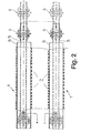
- FIG. 2 shows that the jacket pipe sections 6 of the district heating lines 1 have already been laid in a trench and are covered with soil 7 except for the areas immediately in front of and behind the abutment rings 4.
- the casing pipe sections 6 thus form, as such, more or less stationary abutments for the expansion movement of the medium pipe sections 5.
- Fig. 3 shows in more detail the structure of a district heating line 1 according to the invention in the area of an abutment ring 4. From this illustration it follows that a mechanically fixed, but thermally and electrically insulating connection between the medium pipe 2 and the casing pipe 3 is provided via the abutment ring 4.
- the abutment ring 4 consists of two inner retaining rings 8, an outer retaining ring 9 arranged axially between the inner retaining rings 8 and a plurality of electrically and thermally insulating pressure-receiving elements 10.
- the inner retaining rings 8 are welded to the medium pipe 2, while the outer retaining ring 9 is welded to the Jacket tube 3 is welded.
- the pressure-receiving elements 10 are effective between the two inner retaining rings 8 and the outer retaining ring 9 and absorb the pressure generated by the pretensioning of the medium tube 2 with respect to the jacket tube 3 regardless of the axial direction of action.
- the medium pipe 2 is provided with a sleeve 11 made of insulating material and that an evacuable cavity 12 exists between the sleeve 11 made of insulating material and the inside of the jacket tube 3.
- the medium pipe 2 has a power connection body 13 and the casing tube 3 has an access opening 14 for the power connection body 13.
- the power connection body 13 is brought out through the access opening 14 in an electrically insulated manner with respect to the casing tube 3.
- a reinforcement rib is provided as the power connection body 13, the reinforcement rib having a connection extension 15 which can be removed after the laying process has been completed.
- FIG. 5 again shows two process stages in the installation of a district heating line 1.
- the medium pipe section 5 of the medium pipe 2 is shown before and after heating, recognizable by the different position of the corresponding abutment ring 4.
- the district heating line 1 in the finished installed state i. H. with welded medium pipe sections 5 and with additionally inserted jacket pipe sections 6, by means of which the still open area directly in front of and behind the abutment rina 4 is covered.
- the soil 7 covering and compacting the district heating line 1 is also indicated.
- the power source at one end of the respective medium pipe sections 5 when two district heating lines 1 are laid in parallel, the medium pipe sections 5 only having to be electrically connected to one another at the other ends. Because of the relatively low specific resistance of the medium pipe sections 5, given nominal voltages of the power source between 10 and 26 V for safety reasons, lengths of the line sections of the district heating lines 1 of 100 to 600 meters have proven to be expedient in this constellation.
Priority Applications (1)
| Application Number | Priority Date | Filing Date | Title |
|---|---|---|---|
| AT82110149T ATE23620T1 (de) | 1981-12-12 | 1982-11-04 | Kompensatorfrei verlegbare fernwaermeleitung. |
Applications Claiming Priority (2)
| Application Number | Priority Date | Filing Date | Title |
|---|---|---|---|
| DE3149365A DE3149365C2 (de) | 1981-12-12 | 1981-12-12 | Verfahren zum Verlegen von kompensatorfreien Fernwärmeleitungen |
| DE3149365 | 1981-12-12 |
Publications (2)
| Publication Number | Publication Date |
|---|---|
| EP0081667A1 true EP0081667A1 (fr) | 1983-06-22 |
| EP0081667B1 EP0081667B1 (fr) | 1986-11-12 |
Family
ID=6148618
Family Applications (1)
| Application Number | Title | Priority Date | Filing Date |
|---|---|---|---|
| EP82110149A Expired EP0081667B1 (fr) | 1981-12-12 | 1982-11-04 | Tuyaux posable sans compensateurs pour système de chauffage à grande distance |
Country Status (3)
| Country | Link |
|---|---|
| EP (1) | EP0081667B1 (fr) |
| AT (1) | ATE23620T1 (fr) |
| DE (2) | DE3149365C2 (fr) |
Cited By (5)
| Publication number | Priority date | Publication date | Assignee | Title |
|---|---|---|---|---|
| WO1985002003A1 (fr) * | 1983-10-31 | 1985-05-09 | Otto Tauschmann | Conduite |
| FR2574523A1 (fr) * | 1984-12-06 | 1986-06-13 | Chauffage Distance Cie Gle | Procede de pose de canalisations formees de troncons raccordes et canalisations realisees selon ce procede |
| EP0265677A1 (fr) * | 1986-09-30 | 1988-05-04 | DSD Dillinger Stahlbau GmbH | Point fixe d'une tuyauterie enterrée etant composée d'un tube pour milieu liquide et d'une gaîne |
| WO1999034141A1 (fr) * | 1997-12-24 | 1999-07-08 | Rockwater Limited | Pipeline a double paroi, a tube interne precontraint |
| EP1403578A1 (fr) * | 2002-09-30 | 2004-03-31 | Fränkische Rohrwerke Gebr. Kirchner GmbH + Co KG | Tuyau d'un système de chauffage à grande distance |
Families Citing this family (1)
| Publication number | Priority date | Publication date | Assignee | Title |
|---|---|---|---|---|
| DE3926919C2 (de) * | 1989-08-16 | 1998-02-05 | Motoren Werke Mannheim Ag | Abgaskanal mit isolierendem Leitungselement |
Citations (3)
| Publication number | Priority date | Publication date | Assignee | Title |
|---|---|---|---|---|
| US2592574A (en) * | 1948-10-29 | 1952-04-15 | Edward W Kaiser | Pipe joint fitting |
| US2696835A (en) * | 1950-11-04 | 1954-12-14 | Edward W Kaiser | Conduit construction |
| GB1222246A (en) * | 1968-03-06 | 1971-02-10 | Trans Continental Electronics | Electric resistance heating system for elongated pipes |
Family Cites Families (2)
| Publication number | Priority date | Publication date | Assignee | Title |
|---|---|---|---|---|
| JPS5018286B1 (fr) * | 1969-10-16 | 1975-06-27 | ||
| CH610082A5 (en) * | 1976-05-20 | 1979-03-30 | Meier Schenk Arthur | Method for laying pipelines for hot or cooled heat media |
-
1981
- 1981-12-12 DE DE3149365A patent/DE3149365C2/de not_active Expired
-
1982
- 1982-11-04 DE DE8282110149T patent/DE3274290D1/de not_active Expired
- 1982-11-04 AT AT82110149T patent/ATE23620T1/de not_active IP Right Cessation
- 1982-11-04 EP EP82110149A patent/EP0081667B1/fr not_active Expired
Patent Citations (3)
| Publication number | Priority date | Publication date | Assignee | Title |
|---|---|---|---|---|
| US2592574A (en) * | 1948-10-29 | 1952-04-15 | Edward W Kaiser | Pipe joint fitting |
| US2696835A (en) * | 1950-11-04 | 1954-12-14 | Edward W Kaiser | Conduit construction |
| GB1222246A (en) * | 1968-03-06 | 1971-02-10 | Trans Continental Electronics | Electric resistance heating system for elongated pipes |
Cited By (5)
| Publication number | Priority date | Publication date | Assignee | Title |
|---|---|---|---|---|
| WO1985002003A1 (fr) * | 1983-10-31 | 1985-05-09 | Otto Tauschmann | Conduite |
| FR2574523A1 (fr) * | 1984-12-06 | 1986-06-13 | Chauffage Distance Cie Gle | Procede de pose de canalisations formees de troncons raccordes et canalisations realisees selon ce procede |
| EP0265677A1 (fr) * | 1986-09-30 | 1988-05-04 | DSD Dillinger Stahlbau GmbH | Point fixe d'une tuyauterie enterrée etant composée d'un tube pour milieu liquide et d'une gaîne |
| WO1999034141A1 (fr) * | 1997-12-24 | 1999-07-08 | Rockwater Limited | Pipeline a double paroi, a tube interne precontraint |
| EP1403578A1 (fr) * | 2002-09-30 | 2004-03-31 | Fränkische Rohrwerke Gebr. Kirchner GmbH + Co KG | Tuyau d'un système de chauffage à grande distance |
Also Published As
| Publication number | Publication date |
|---|---|
| EP0081667B1 (fr) | 1986-11-12 |
| DE3274290D1 (en) | 1987-01-02 |
| DE3149365C2 (de) | 1984-09-20 |
| DE3149365A1 (de) | 1983-06-23 |
| ATE23620T1 (de) | 1986-11-15 |
Similar Documents
| Publication | Publication Date | Title |
|---|---|---|
| DD255579A5 (de) | Verfahren und vorrichtung fuer das auskleiden und umwickeln von rohrleitungen und das auskleiden von kanaelen | |
| DE3528061C2 (fr) | ||
| DE2050035A1 (fr) | ||
| EP0081667B1 (fr) | Tuyaux posable sans compensateurs pour système de chauffage à grande distance | |
| DE69836611T2 (de) | Abgedichtete Schutzvorrichtung für Hochspannungskabelverbindung | |
| DE2316123A1 (de) | Elektrische kaelteverbindung an vakuumisolierten kabeln | |
| DE4328411A1 (de) | Verfahren und Vorrichtung zum Anschließen und Abdichten eines Seitenzulaufs an einen mit einem Inliner aus Kunststoff zu sanierenden Hauptkanal | |
| DE3315819A1 (de) | Rohrleitung (pipeline) zur foerderung von insbesondere aggresiven medien und verfahren zum zusammensetzen bzw. verlegen der rohrleitung | |
| DE3814176C2 (de) | Doppelwandige Rohrleitung aus einer Vielzahl endseitig miteinander verbundener Rohrlängen | |
| DE3112101C2 (de) | Einrichtung für den Zusammenschluß von Wellrohrenden einer trommelbaren Koaxial-Wellrohr-Fernheizleitung | |
| DE3413747A1 (de) | Festpunkt fuer eine rohrleitung | |
| EP0414891A1 (fr) | Procede et dispositif pour la pose de canalisations sans tranchees | |
| EP1046854A2 (fr) | Raccord à manchon pour connecter deux tuyaux et un dispositif de verrouillage pour un raccord à manchon | |
| DE2610297A1 (de) | Verfahren zur herstellung einer unloesbaren verbindung zwischen gewellten metallrohren | |
| DE3316482A1 (de) | Verfahren zum verlegen eines aus einzelnen waermeisolierten leitungsrohren bestehenden rohrstranges | |
| AT323487B (de) | Von einem schutzmantel umgebene isolierte rohrleitung nebst verbindungselement zum ansetzen von weitern rohrleitungsstucken | |
| EP0445902A1 (fr) | Conduite isolée thermiquement | |
| EP0201479A2 (fr) | Appareil pour le soudage de deux éléments tubulaires en matière plastique emboîtés l'un dans l'autre | |
| DE3125626A1 (de) | Verfahren und stuetzring zur herstellung einer rohr-schweissverbindung | |
| AT357946B (de) | Vorrichtung zum vortrieb eines aus mindestens einem rohrabschnitt bestehenden rohres im erdboden | |
| EP0011252A1 (fr) | Manchon d'accouplement pour tuyau | |
| DE2934423A1 (de) | Verfahren zum elektrischen stumpfschweissen von metallischen leitern | |
| DE2945709C2 (fr) | ||
| EP1433989B1 (fr) | Dispositif pour le transport de substances fluides à plusieurs phases | |
| DE2460954C3 (de) | Wassergekühltes Hochspannungsenergiekabel mit äußerer thermischer Isolation |
Legal Events
| Date | Code | Title | Description |
|---|---|---|---|
| PUAI | Public reference made under article 153(3) epc to a published international application that has entered the european phase |
Free format text: ORIGINAL CODE: 0009012 |
|
| AK | Designated contracting states |
Designated state(s): AT BE CH DE FR GB IT LI LU NL SE |
|
| 17P | Request for examination filed |
Effective date: 19830802 |
|
| GRAA | (expected) grant |
Free format text: ORIGINAL CODE: 0009210 |
|
| AK | Designated contracting states |
Kind code of ref document: B1 Designated state(s): AT BE CH DE FR GB IT LI LU NL SE |
|
| PG25 | Lapsed in a contracting state [announced via postgrant information from national office to epo] |
Ref country code: NL Effective date: 19861112 Ref country code: IT Free format text: LAPSE BECAUSE OF FAILURE TO SUBMIT A TRANSLATION OF THE DESCRIPTION OR TO PAY THE FEE WITHIN THE PRESCRIBED TIME-LIMIT;WARNING: LAPSES OF ITALIAN PATENTS WITH EFFECTIVE DATE BEFORE 2007 MAY HAVE OCCURRED AT ANY TIME BEFORE 2007. THE CORRECT EFFECTIVE DATE MAY BE DIFFERENT FROM THE ONE RECORDED. Effective date: 19861112 Ref country code: FR Free format text: LAPSE BECAUSE OF NON-PAYMENT OF DUE FEES Effective date: 19861112 Ref country code: BE Effective date: 19861112 |
|
| REF | Corresponds to: |
Ref document number: 23620 Country of ref document: AT Date of ref document: 19861115 Kind code of ref document: T |
|
| PG25 | Lapsed in a contracting state [announced via postgrant information from national office to epo] |
Ref country code: SE Effective date: 19861130 |
|
| REF | Corresponds to: |
Ref document number: 3274290 Country of ref document: DE Date of ref document: 19870102 |
|
| EN | Fr: translation not filed | ||
| NLV1 | Nl: lapsed or annulled due to failure to fulfill the requirements of art. 29p and 29m of the patents act | ||
| PLBI | Opposition filed |
Free format text: ORIGINAL CODE: 0009260 |
|
| 26 | Opposition filed |
Opponent name: DSD DILLINGER STAHLBAU GMBH Effective date: 19870811 |
|
| PG25 | Lapsed in a contracting state [announced via postgrant information from national office to epo] |
Ref country code: GB Effective date: 19871104 |
|
| RDAG | Patent revoked |
Free format text: ORIGINAL CODE: 0009271 |
|
| STAA | Information on the status of an ep patent application or granted ep patent |
Free format text: STATUS: PATENT REVOKED |
|
| 27W | Patent revoked |
Effective date: 19871127 |
|
| REG | Reference to a national code |
Ref country code: CH Ref legal event code: PL |
|
| GBPC | Gb: european patent ceased through non-payment of renewal fee | ||
| GBPR | Gb: patent revoked under art. 102 of the ep convention designating the uk as contracting state | ||
| REG | Reference to a national code |
Ref country code: GB Ref legal event code: 7102 |