EP0081400B1 - Dispositif de chauffage par induction magnétique de produits métalliques rectangulaires plats défilant dans le sens de leur longueur - Google Patents
Dispositif de chauffage par induction magnétique de produits métalliques rectangulaires plats défilant dans le sens de leur longueur Download PDFInfo
- Publication number
- EP0081400B1 EP0081400B1 EP82401998A EP82401998A EP0081400B1 EP 0081400 B1 EP0081400 B1 EP 0081400B1 EP 82401998 A EP82401998 A EP 82401998A EP 82401998 A EP82401998 A EP 82401998A EP 0081400 B1 EP0081400 B1 EP 0081400B1
- Authority
- EP
- European Patent Office
- Prior art keywords
- inductor
- heating device
- pole
- axis
- polar
- Prior art date
- Legal status (The legal status is an assumption and is not a legal conclusion. Google has not performed a legal analysis and makes no representation as to the accuracy of the status listed.)
- Expired
Links
- 238000010438 heat treatment Methods 0.000 title claims description 40
- 239000002184 metal Substances 0.000 claims description 34
- 230000006698 induction Effects 0.000 claims description 8
- 230000000694 effects Effects 0.000 description 5
- 238000010586 diagram Methods 0.000 description 3
- 230000004907 flux Effects 0.000 description 3
- 238000005096 rolling process Methods 0.000 description 3
- 238000004804 winding Methods 0.000 description 3
- 238000013459 approach Methods 0.000 description 1
- 239000004020 conductor Substances 0.000 description 1
- 230000005284 excitation Effects 0.000 description 1
- 238000004519 manufacturing process Methods 0.000 description 1
- 239000011819 refractory material Substances 0.000 description 1
Images

Classifications
-
- H—ELECTRICITY
- H05—ELECTRIC TECHNIQUES NOT OTHERWISE PROVIDED FOR
- H05B—ELECTRIC HEATING; ELECTRIC LIGHT SOURCES NOT OTHERWISE PROVIDED FOR; CIRCUIT ARRANGEMENTS FOR ELECTRIC LIGHT SOURCES, IN GENERAL
- H05B6/00—Heating by electric, magnetic or electromagnetic fields
- H05B6/02—Induction heating
- H05B6/10—Induction heating apparatus, other than furnaces, for specific applications
- H05B6/101—Induction heating apparatus, other than furnaces, for specific applications for local heating of metal pieces
- H05B6/102—Induction heating apparatus, other than furnaces, for specific applications for local heating of metal pieces the metal pieces being rotated while induction heated
-
- H—ELECTRICITY
- H05—ELECTRIC TECHNIQUES NOT OTHERWISE PROVIDED FOR
- H05B—ELECTRIC HEATING; ELECTRIC LIGHT SOURCES NOT OTHERWISE PROVIDED FOR; CIRCUIT ARRANGEMENTS FOR ELECTRIC LIGHT SOURCES, IN GENERAL
- H05B6/00—Heating by electric, magnetic or electromagnetic fields
- H05B6/02—Induction heating
- H05B6/36—Coil arrangements
- H05B6/365—Coil arrangements using supplementary conductive or ferromagnetic pieces
Definitions
- the present invention relates to a device for heating by magnetic induction of flat rectangular metal products running in the direction of their length, of the type comprising at least one inductor capable of producing a magnetic field of constant intensity, but adjustable, oriented substantially perpendicular to a large face of the metal product to be heated, said inductor being rotatably mounted about an axis perpendicular to said large face of the metal product and comprising at least two magnetic poles having polar surfaces oriented towards said large face are parallel to these, and scanning an annular area when the inductor rotates.
- the magnetic poles can be formed by permanent magnets, electromagnets or a combination of permanent magnets and electromagnets.
- the inductor (s) can be placed outside a tunnel made of refractory material and permeable to the magnetic field, inside which pass the metallic products to be heated.
- the present invention therefore aims to solve this problem by providing an improved device for magnetic induction heating to improve the uniformity of the heating in the transverse direction of the metal products running in the direction of their length, and this whatever the width of metal products within a given width range.
- the magnetic induction heating device is characterized in that the pole surface of each pole has the shape of a curvilinear triangle having a vertex directed towards the axis of rotation of the inductor, two concave sides which are symmetrical with respect to a straight line passing through said vertex and perpendicular to said axis, and a convex side in an arc centered on said axis and whose radius of curvature is substantially equal to the outside radius of the annular zone swept by polar surfaces of the poles.
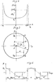
- the conventional magnetic induction heating device which is shown diagrammatically in FIG. 1 and to which the present invention can be applied comprises, for example, two inductors 1 and 2 arranged respectively above and below the metal product 3 to be heated, for example a slab, facing the large faces of the slab 3, the latter being driven by a continuous movement in a direction perpendicular to the plane of the figure, that is to say in the direction of its length.
- each of the two inductors comprises several magnetic poles, for example two magnetic poles 4.
- the poles 4 can be constituted by permanent magnets, by wound poles whose windings are supplied with direct current (electromagnet), or by permanent magnets surrounded by windings which can be supplied with direct current.
- the intensity of the direct current can be adjusted in a known manner in order to adjust the intensity of the magnetic field produced by the magnets and, consequently, the intensity of the heating produced by the eddy currents induced in the metallic product 3 to be heated.
- the poles 4 have a circular section (this shape corresponds to a maximum magnetic flux for a given length of conductor and therefore for given Joule losses in the case of wound poles).
- At least one of the inductors 1 and 2 is rotated about the vertical axis z by known means not shown in Figure 1, the other inductor can be rotated synchronously either by the same means of drive, or by the magnetic field produced by the first inductor.
- the speed of rotation of the inductors 1 and 2 is usually significantly greater than the speed of advance of the metal product 3.
- the pole surfaces of the poles 4 which are located opposite the large faces of the metal product 3 scan an annular zone 5 as shown in FIG. 2. This zone 5 roughly corresponds to the zone of action of the inductors on the metal product 3 to be heated.
- the width of the metal product 3 to be heated does not allow homogeneous heating to be obtained over the entire width of the product 3 while it is advancing.
- a heating device the dimensions of which are such that the outside diameter of its annular action zone 5 is significantly greater than the maximum width of the metallic products. 3 to be heated, so as to operate in the middle part of the heating profile C. It is therefore necessary to use heating devices which are large in relation to the width of the metal products 3 to be heated. Under these conditions, it will be noted that the magnetic flux produced by the inductors is not fully used for heating, since it does not act on the metal product 3 to be heated when, during their rotation, the magnetic poles are found beyond the longitudinal sides of product 3, hence a lower yield.
- the present invention makes it possible to remedy this by providing a heating device having dimensions such that the diameter of its area of action is only very slightly greater than the maximum width of the moving metal products to be heated, and making it possible to heat the said areas. substantially homogeneously produced over their entire width with good yield.
- this result can be obtained by using one or two inductors arranged like those of FIG. 1, but whose magnetic poles, constituted for example by electromagnets, have polar surfaces in the shape of a curvilinear triangle.
- FIG. 3 shows by way of example, in front view, an inductor according to the present invention comprising four magnetic poles 4 of identical shapes and of alternating polarities.
- Each magnetic pole 4 may comprise a magnetic core 6, for example of circular cross section, around which is arranged an excitation winding (not shown) supplied with direct current.
- Each core 6 is provided with a pole shoe or pole piece 7 which is an integral part of the core 6 or which is fixed to the end of the core which is adjacent to the metal product to be heated.
- Each pole shoe 7 has a flat pole surface parallel to one of the large faces of the metal product to be heated.
- each bloom 7 has the shape of a curvilinear triangle which has a vertex 8 directed towards the axis of rotation z of the inductor, two concave sides 9 and 10, which are symmetrical with respect to a straight line passing through the apex 8 and perpendicular to the z axis, and a convex side 11 in an arc of a circle centered on the z axis and whose radius of curvature is substantially equal to the outside radius R of the annular zone 6 swept by the polar surfaces.
- equation (1) The solution of equations (5) and (6) is provided by equation (1). Indeed, taking into account equations (1) and (3), equation (5) can be written: from where: from where: which gives E m independent of d.
- the variation in the time of the magnetic field B seen by the point P, of polar coordinates r, a (figures 3 and 5) during the rotation of the inductor can be represented by a succession of slots alternately positive and negative as shown in the figure 6.
- Each slot corresponds to the passage of a pole 4 in front of the point P and has a width which corresponds to the length of the polar arc 8 (figure 3) of each pole 4 at the distance r at which the point P is located
- This waveform of the magnetic field B seen by the point P can be decompensated in Fournier series and expressed by the relation:
- Equation (11) Equation (11) then becomes: which can still be written: with:
- each of the pole shoes 7 the shape of a curvilinear triangle whose concave sides 9 and 10 are arcs of a circle having a profile which approaches the determined ideal profile. as described above, and the convex side 11 of which is an arc of a circle having a radius of curvature substantially equal to the outside radius of the annular zone swept by the poles 4, this outside radius itself being slightly larger than the half the maximum width of metal products to be heated.
- each polar surface in the shape of a curvilinear triangle is preferably symmetrical with respect to the straight line passing through its apex 8 and through the center O of the rotating inductor, in order to obtain better balancing of the rotating masses.
- the apex 8 of each curvilinear triangle is preferably truncated to avoid the leakage of magnetic flux between the poles 4 of opposite polarities.
Landscapes
- Physics & Mathematics (AREA)
- Electromagnetism (AREA)
- General Induction Heating (AREA)
Applications Claiming Priority (2)
| Application Number | Priority Date | Filing Date | Title |
|---|---|---|---|
| FR8121238A FR2516641A1 (fr) | 1981-11-13 | 1981-11-13 | Dispositif de chauffage par induction magnetique de produits metalliques rectangulaires plats defilant dans le sens de leur longueur |
| FR8121238 | 1981-11-13 |
Publications (2)
| Publication Number | Publication Date |
|---|---|
| EP0081400A1 EP0081400A1 (fr) | 1983-06-15 |
| EP0081400B1 true EP0081400B1 (fr) | 1986-08-27 |
Family
ID=9263961
Family Applications (1)
| Application Number | Title | Priority Date | Filing Date |
|---|---|---|---|
| EP82401998A Expired EP0081400B1 (fr) | 1981-11-13 | 1982-10-28 | Dispositif de chauffage par induction magnétique de produits métalliques rectangulaires plats défilant dans le sens de leur longueur |
Country Status (5)
| Country | Link |
|---|---|
| US (1) | US4481397A (enExample) |
| EP (1) | EP0081400B1 (enExample) |
| JP (1) | JPS5894789A (enExample) |
| DE (1) | DE3272924D1 (enExample) |
| FR (1) | FR2516641A1 (enExample) |
Families Citing this family (14)
| Publication number | Priority date | Publication date | Assignee | Title |
|---|---|---|---|---|
| NL8304240A (nl) * | 1983-12-08 | 1985-07-01 | Skf Ind Trading & Dev | Wiellager. |
| US4761527A (en) * | 1985-10-04 | 1988-08-02 | Mohr Glenn R | Magnetic flux induction heating |
| US4856097A (en) * | 1988-03-29 | 1989-08-08 | Glenn Mohr | Apparatus for induction heating of electrically conductive metal wire and strip |
| US5529703A (en) * | 1990-06-04 | 1996-06-25 | Nordson Corporation | Induction dryer and magnetic separator |
| US5483042A (en) * | 1990-06-04 | 1996-01-09 | Nordson Corporation | Magnetic separator |
| US5847370A (en) * | 1990-06-04 | 1998-12-08 | Nordson Corporation | Can coating and curing system having focused induction heater using thin lamination cores |
| DE69132177T2 (de) * | 1990-11-30 | 2000-12-21 | Nordson Corp., Westlake | Induktionstrockner und Magnetscheider |
| WO1993023970A1 (en) * | 1992-05-08 | 1993-11-25 | Heron Technologies, Inc. | Induction dryer and magnetic separator |
| NZ282347A (en) * | 1994-03-16 | 1999-01-28 | Larkden Pty Ltd | Converting rotational energy of shaft into heat, inducing eddy currents in graphite block |
| FR2733553B1 (fr) * | 1995-04-25 | 1997-07-11 | Pem Sa Protection Electrolytiq | Dispositif de contre-collage pour la solidarisation d'une bande metallique et d'une bande de materiau isolant |
| DE102008014165A1 (de) * | 2008-03-14 | 2009-09-24 | Ab Skf | Vorrichtung zum Erwärmen und Verfahren zum Erwärmen |
| EP2274953B1 (en) | 2008-04-11 | 2015-07-15 | The Timken Company | Inductive heating using permanent magnets for hardening of gear teeth and components alike |
| US8993942B2 (en) | 2010-10-11 | 2015-03-31 | The Timken Company | Apparatus for induction hardening |
| EP3199647B1 (en) * | 2010-10-11 | 2019-07-31 | The Timken Company | Apparatus for induction hardening |
Family Cites Families (6)
| Publication number | Priority date | Publication date | Assignee | Title |
|---|---|---|---|---|
| FR916287A (fr) * | 1944-04-01 | 1946-12-02 | Brown | Procédé et dispositif pour le chauffage électrique de pièces métalliques |
| CH264034A (de) * | 1947-10-28 | 1949-09-30 | Bbc Brown Boveri & Cie | Verfahren zum induktiven Erhitzen metallischer, plattenförmiger Werkstücke. |
| GB1036725A (en) * | 1962-05-05 | 1966-07-20 | Delapena & Sons Ltd | Improvements in or relating to induction heating |
| CH416879A (de) * | 1963-04-01 | 1966-07-15 | Baermann Max | Ofen zur Erwärmung von metallischen Teilen |
| FR1387653A (fr) * | 1964-03-31 | 1965-01-29 | Four pour le chauffage de pièces métalliques | |
| FR2473244A1 (fr) * | 1980-01-04 | 1981-07-10 | Cem Comp Electro Mec | Procede et dispositif de chauffage electrique par induction de produits metalliques, utilisant des champs magnetiques pulses |
-
1981
- 1981-11-13 FR FR8121238A patent/FR2516641A1/fr active Granted
-
1982
- 1982-10-28 EP EP82401998A patent/EP0081400B1/fr not_active Expired
- 1982-10-28 DE DE8282401998T patent/DE3272924D1/de not_active Expired
- 1982-11-12 US US06/441,094 patent/US4481397A/en not_active Expired - Fee Related
- 1982-11-12 JP JP57197883A patent/JPS5894789A/ja active Granted
Also Published As
| Publication number | Publication date |
|---|---|
| DE3272924D1 (en) | 1986-10-02 |
| FR2516641A1 (fr) | 1983-05-20 |
| JPS5894789A (ja) | 1983-06-06 |
| FR2516641B1 (enExample) | 1984-01-27 |
| EP0081400A1 (fr) | 1983-06-15 |
| US4481397A (en) | 1984-11-06 |
| JPS623554B2 (enExample) | 1987-01-26 |
Similar Documents
| Publication | Publication Date | Title |
|---|---|---|
| EP1148762B1 (fr) | Dispositif de chauffage par induction à flux transverse à circuit magnétique de largeur variable | |
| EP0081400A1 (fr) | Dispositif de chauffage par induction magnétique de produits métalliques rectangulaires plats défilant dans le sens de leur longueur | |
| EP3595133B1 (fr) | Moteur électrique optimisé à dents étroites | |
| EP0576352B1 (fr) | Dispositif de chauffage inductif homogène de produits plats métalliques au défilé | |
| FR1464391A (fr) | Machine électrique à disques | |
| EP0022707B1 (fr) | Dispositif de chauffage par induction de produits longs et minces en défilement continu | |
| EP0527937B1 (fr) | Procede et dispositifs de rechauffage par induction au defile d'un produit metallurgique de forme allongee | |
| FR2589306A1 (fr) | Appareil de chauffage par induction electromagnetique | |
| CH353071A (fr) | Machine électrique tournante | |
| EP0080921B1 (fr) | Procédé et dispositif pour obtenir une homogénéité transversale de chauffage par induction électromagnétique de produits longs et minces en défilement continu | |
| EP0150793B1 (fr) | Dispositif de chauffage de produits plats au défilé par induction électromagnétique | |
| LU88394A1 (fr) | Coupleur magnétique à hystérésis | |
| FR2589384A1 (fr) | Dispositif de tronconnage de tubes | |
| FR2895638A1 (fr) | Dispositif inducteur a bobinages individuels multiples pour foyer de cuisson par induction | |
| EP0340082A1 (fr) | Dispositif de tronçonnage de tubes | |
| CA2647583C (fr) | Coupleur magnetique a hysteresis, notamment pour dispositifs enrouleurs-derouleurs | |
| EP0053060B2 (fr) | Inducteur à champ glissant et à flux orienté pour rouleau-brasseur de coulée continue de brames | |
| FR2532112A1 (fr) | Procede pour faire varier en fonction du temps la trajectoire d'un faisceau de particules chargees | |
| EP0321332B1 (fr) | Moteur électrique à haut rendement et à faible ondulation de couple | |
| LU88395A1 (fr) | Coupleur magnétique à hystérésis | |
| FR2536943A1 (fr) | Procede et dispositif de chauffage par induction d'une piece ferromagnetique a symetrie axiale et a contour irregulier | |
| EP1174986A1 (fr) | Rotor feuilleté pour frein à courants de Foucault et dispositif comportant un tel rotor | |
| EP0072297B1 (fr) | Machine électrique à courant continu, à entrefer cylindrique et à excitation permanente | |
| EP0471059A1 (fr) | Generateur electromecanique de vibrations et dispositif utilisant ce generateur | |
| BE465760A (enExample) |
Legal Events
| Date | Code | Title | Description |
|---|---|---|---|
| PUAI | Public reference made under article 153(3) epc to a published international application that has entered the european phase |
Free format text: ORIGINAL CODE: 0009012 |
|
| 17P | Request for examination filed |
Effective date: 19830122 |
|
| AK | Designated contracting states |
Designated state(s): BE CH DE GB IT LI LU |
|
| RAP1 | Party data changed (applicant data changed or rights of an application transferred) |
Owner name: ALSTHOM |
|
| GRAA | (expected) grant |
Free format text: ORIGINAL CODE: 0009210 |
|
| AK | Designated contracting states |
Kind code of ref document: B1 Designated state(s): BE CH DE GB IT LI LU |
|
| REF | Corresponds to: |
Ref document number: 3272924 Country of ref document: DE Date of ref document: 19861002 |
|
| ITF | It: translation for a ep patent filed | ||
| PLBE | No opposition filed within time limit |
Free format text: ORIGINAL CODE: 0009261 |
|
| STAA | Information on the status of an ep patent application or granted ep patent |
Free format text: STATUS: NO OPPOSITION FILED WITHIN TIME LIMIT |
|
| 26N | No opposition filed | ||
| PGFP | Annual fee paid to national office [announced via postgrant information from national office to epo] |
Ref country code: GB Payment date: 19920821 Year of fee payment: 11 |
|
| PGFP | Annual fee paid to national office [announced via postgrant information from national office to epo] |
Ref country code: CH Payment date: 19920917 Year of fee payment: 11 |
|
| PGFP | Annual fee paid to national office [announced via postgrant information from national office to epo] |
Ref country code: BE Payment date: 19921001 Year of fee payment: 11 |
|
| PGFP | Annual fee paid to national office [announced via postgrant information from national office to epo] |
Ref country code: DE Payment date: 19921016 Year of fee payment: 11 |
|
| ITTA | It: last paid annual fee | ||
| PGFP | Annual fee paid to national office [announced via postgrant information from national office to epo] |
Ref country code: LU Payment date: 19921123 Year of fee payment: 11 |
|
| EPTA | Lu: last paid annual fee | ||
| PG25 | Lapsed in a contracting state [announced via postgrant information from national office to epo] |
Ref country code: LU Free format text: LAPSE BECAUSE OF NON-PAYMENT OF DUE FEES Effective date: 19931028 Ref country code: GB Effective date: 19931028 |
|
| PG25 | Lapsed in a contracting state [announced via postgrant information from national office to epo] |
Ref country code: LI Effective date: 19931031 Ref country code: CH Effective date: 19931031 Ref country code: BE Effective date: 19931031 |
|
| BERE | Be: lapsed |
Owner name: ALSTHOM Effective date: 19931031 |
|
| GBPC | Gb: european patent ceased through non-payment of renewal fee |
Effective date: 19931028 |
|
| REG | Reference to a national code |
Ref country code: CH Ref legal event code: PL |
|
| PG25 | Lapsed in a contracting state [announced via postgrant information from national office to epo] |
Ref country code: DE Effective date: 19940701 |