EP0080438B1 - Vorrichtung zur Formung von Flanschen an hohlzylindrischen Blechwerkstücken - Google Patents
Vorrichtung zur Formung von Flanschen an hohlzylindrischen Blechwerkstücken Download PDFInfo
- Publication number
- EP0080438B1 EP0080438B1 EP82830276A EP82830276A EP0080438B1 EP 0080438 B1 EP0080438 B1 EP 0080438B1 EP 82830276 A EP82830276 A EP 82830276A EP 82830276 A EP82830276 A EP 82830276A EP 0080438 B1 EP0080438 B1 EP 0080438B1
- Authority
- EP
- European Patent Office
- Prior art keywords
- flanging
- machine frame
- machine
- workpiece
- flanging machine
- Prior art date
- Legal status (The legal status is an assumption and is not a legal conclusion. Google has not performed a legal analysis and makes no representation as to the accuracy of the status listed.)
- Expired
Links
- 239000002184 metal Substances 0.000 title claims abstract description 13
- 230000020347 spindle assembly Effects 0.000 claims abstract description 4
- 230000007246 mechanism Effects 0.000 claims description 4
- 238000005096 rolling process Methods 0.000 claims description 3
- 238000007493 shaping process Methods 0.000 claims description 3
- 239000011324 bead Substances 0.000 description 1
- 230000015572 biosynthetic process Effects 0.000 description 1
- 230000006835 compression Effects 0.000 description 1
- 238000007906 compression Methods 0.000 description 1
- 238000010276 construction Methods 0.000 description 1
- 238000012986 modification Methods 0.000 description 1
- 230000004048 modification Effects 0.000 description 1
- 230000000717 retained effect Effects 0.000 description 1
- 125000006850 spacer group Chemical group 0.000 description 1
Images

Classifications
-
- B—PERFORMING OPERATIONS; TRANSPORTING
- B21—MECHANICAL METAL-WORKING WITHOUT ESSENTIALLY REMOVING MATERIAL; PUNCHING METAL
- B21D—WORKING OR PROCESSING OF SHEET METAL OR METAL TUBES, RODS OR PROFILES WITHOUT ESSENTIALLY REMOVING MATERIAL; PUNCHING METAL
- B21D19/00—Flanging or other edge treatment, e.g. of tubes
- B21D19/02—Flanging or other edge treatment, e.g. of tubes by continuously-acting tools moving along the edge
- B21D19/04—Flanging or other edge treatment, e.g. of tubes by continuously-acting tools moving along the edge shaped as rollers
- B21D19/046—Flanging or other edge treatment, e.g. of tubes by continuously-acting tools moving along the edge shaped as rollers for flanging edges of tubular products
Definitions
- the present invention generally relates to a flanging machine for metal sheet workpieces having a hollow cylindrical symmetry.
- the flanging machines are machines of small/middle power which form beads or rims on workpieces having a cylindrical symmetry, and formed of metal sheets having small/middle thickness.
- These flanging machines have generally a frame provided with a pair of parallel extending roller spindles of which the one is placed over the other, the lower spindle being in a fixed position and the upper spindle being adjustable in height to control the pressure exerted on and the depth of the rim.
- the pair of spindles are rotated and the rollers, by pressing on the metal sheet, form the rim or the beading.
- US-A-1 634 057 discloses a flanging machine for rotatable workpieces comprising a shaping mechanism formed of a pair of roller spindles, a pair of adjustable rolls of cylindrical shape, a pivotal mounting of the roller/spindle assembly on the machine frame, driving means for the pivotal movement, supporting means for the rotatable workpiece on the machine frame.
- a flanging machine having a hollow cylindrical symmetry, of the type comprising a shaping mechanism formed of a pair of parallel extending roll spindles, a pair of adjustable rolls of cylindrical shape, a pivotal mounting of the roll/spindle assembly on the machine frame, driving means for the pivotal movement, means for supporting the rotatable workpiece on the machine frame, characterized in that said pivoting assembly includes a motor driving the spindles with the associated driving elements and in that the supporting means for the rotatable workpiece on the machine frame comprise a ring having an outer diameter corresponding to the inner diameter of the workpiece and being supported by a wheel rotatable mounted on said machine frame, means being provided for guiding the workpiece during all the flanging operation.
- the means for pivoting the above mentioned assembly are formed of a hydraulic and/or pneumatic cylinder connected on the one hand to the machine frame and on the other hand to the pivoting assembly.
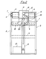
- the flanging machine generally indicated with the numeral 1, includes a machine frame 2 formed of a pair of side walls 3 connected to each other by cross-beams 4 and a front upright 5. Pivotally mounted to the side walls 3 by means of pins 7 is a pivoting frame 6 supporting the parallel extending spindles 8 and 9 placed one over the other, the lower spindle 8 being in a fixed position and the upper spindle 9 being adjustable in height by conventional means, not shown.
- Each of the spindles 8 and 9 supports at the front end thereof a cylindrical roller 10 and 11 respectively, which are intended to perform the flanging operation.
- the driving elements of the spindles 8 and 9 are enclosed within a box 12 to which the driving motor 13 is secured which is connected to a reduction gear 14 through a pulley and belt drive, generally indicated with 15.
- the spindles 8, 9, the cylindrical rollers 10, 11, the motor 13, the reduction gear 14 and the driving elements enclosed within the box 12 are fastened to the pivoting frame 6.
- the pivoting frame 6 is also connected to the machine frame 1 through a hydraulic cylinder 16 operated by a pump 17.
- a pin 18 On the upright 5 of the machine frame 1 a pin 18 is mounted, which carries a flanged wheel 19 supporting a calibrating ring 20 placed directly in front of the lower cylindrical roller 10 and forming an upper tangential point therewith.
- a spacer 21 serves to the exact positioning of the supporting flanged wheel 19 and therefore of the calibrating ring 20 in front of the lower roller 10.
- the calibrating ring 20 bears also on a pair of rolling bearings 22 secured to the upright 5 of the machine frame 1, in an adjustable manner to accommodate different diameters of rings 20.
- the calibrating ring 20 is provided to support the end of the tube to be flanged and to prevent this tube end from being deformed during the flanging operation, since the ring has an outer diameter corresponding to the inner diameter of the tube to be flanged.
- a disc 23 is provided, which supports and guides the tube to be flanged, and is rotatably mounted in the pin 18.
- the pivot axis 0 of the pivoting frame 6 exactly intersects the tangential points of the pair of cylindrical rollers 10, 11 therebetween and of the calibrating ring 20 with the lower roller 10.
- the operation of the flanging machine according to the invention is very simple. Assume that a metal sheet tube is to be flanged having an outer diameter of 300 mm and a wall thickness of 2 mm, on the supporting wheel 19 a calibrating ring having an outer diameter of 286 mm will be applied, which will be retained in position by the wheel 19 through the flanged portion thereof and the rolling bearings 22 will be adjusted accordingly.
- the tube to be flanged is inserted on the guide disc 23 and is slid until the end thereof is placed between the cylindrical rollers 10 and 11 against an abutment 24 provided on the spindle 8 acting as a stop for the edge of the tube on the rollers 10, 11.
- the upper roller 11 is adjusted in height until it bears against the outer surface of the tube and the motor 13 is energized, which will rotate the spindles 8 and 9 and therefore the cylindrical rollers 10, 11 and the tube.
- rollers 10, 11 lie with their axes perpendicular to the tube axis and the tube length pressed between the rollers is bent at 90° to the tube axis.
- a flange having a height corresponding to the length of the rollers 10, 11 and the pivoting frame 6 will be in the position shown in dashed line in Figure 1.
Landscapes
- Engineering & Computer Science (AREA)
- Mechanical Engineering (AREA)
- Bending Of Plates, Rods, And Pipes (AREA)
- Shaping Metal By Deep-Drawing, Or The Like (AREA)
- Press Drives And Press Lines (AREA)
- Basic Packing Technique (AREA)
Claims (4)
Priority Applications (1)
| Application Number | Priority Date | Filing Date | Title |
|---|---|---|---|
| AT82830276T ATE19966T1 (de) | 1981-11-19 | 1982-11-09 | Vorrichtung zur formung von flanschen an hohlzylindrischen blechwerkstuecken. |
Applications Claiming Priority (2)
| Application Number | Priority Date | Filing Date | Title |
|---|---|---|---|
| IT2519481 | 1981-11-19 | ||
| IT25194/81A IT1139812B (it) | 1981-11-19 | 1981-11-19 | Bordatrice-flangiatrice per pezzi a simmetria cilindrica in lamiera |
Publications (3)
| Publication Number | Publication Date |
|---|---|
| EP0080438A2 EP0080438A2 (de) | 1983-06-01 |
| EP0080438A3 EP0080438A3 (en) | 1983-08-03 |
| EP0080438B1 true EP0080438B1 (de) | 1986-05-28 |
Family
ID=11215979
Family Applications (1)
| Application Number | Title | Priority Date | Filing Date |
|---|---|---|---|
| EP82830276A Expired EP0080438B1 (de) | 1981-11-19 | 1982-11-09 | Vorrichtung zur Formung von Flanschen an hohlzylindrischen Blechwerkstücken |
Country Status (4)
| Country | Link |
|---|---|
| EP (1) | EP0080438B1 (de) |
| AT (1) | ATE19966T1 (de) |
| DE (1) | DE3271448D1 (de) |
| IT (1) | IT1139812B (de) |
Families Citing this family (2)
| Publication number | Priority date | Publication date | Assignee | Title |
|---|---|---|---|---|
| DE3939016A1 (de) * | 1989-11-25 | 1991-05-29 | Xaver Lipp | Vorrichtung zum formen eines flansches oder dergleichen, insbesondere am ende eines duennwandigen metallrohres |
| CN111590364B (zh) * | 2020-06-22 | 2024-08-13 | 大连弘大特种风机有限公司 | 一种圆筒内翻边机床 |
Family Cites Families (3)
| Publication number | Priority date | Publication date | Assignee | Title |
|---|---|---|---|---|
| US1634057A (en) * | 1925-03-06 | 1927-06-28 | Taylor James Hall | Machine for shaping pipes |
| US1782641A (en) * | 1928-06-20 | 1930-11-25 | Wild Otto | Machine for flanging plate disks |
| FI73152C (fi) * | 1979-05-28 | 1987-09-10 | Waertsilae Oy Ab | Anordning foer kragning av roer. |
-
1981
- 1981-11-19 IT IT25194/81A patent/IT1139812B/it active
-
1982
- 1982-11-09 AT AT82830276T patent/ATE19966T1/de not_active IP Right Cessation
- 1982-11-09 DE DE8282830276T patent/DE3271448D1/de not_active Expired
- 1982-11-09 EP EP82830276A patent/EP0080438B1/de not_active Expired
Also Published As
| Publication number | Publication date |
|---|---|
| ATE19966T1 (de) | 1986-06-15 |
| IT8125194A0 (it) | 1981-11-19 |
| DE3271448D1 (en) | 1986-07-03 |
| EP0080438A2 (de) | 1983-06-01 |
| IT1139812B (it) | 1986-09-24 |
| EP0080438A3 (en) | 1983-08-03 |
Similar Documents
| Publication | Publication Date | Title |
|---|---|---|
| US6434994B2 (en) | Roll-forming machine | |
| US4604885A (en) | Machine for the bending of stranded material | |
| JPH07132343A (ja) | 回転鍛造装置 | |
| CN112170533A (zh) | 通用型自动制管机 | |
| US4064727A (en) | Roll forming machine | |
| JP4091543B2 (ja) | ランフラット用ホイールのためのランフラット用支持体を製造する方法 | |
| EP0080438A2 (de) | Vorrichtung zur Formung von Flanschen an hohlzylindrischen Blechwerkstücken | |
| CN216324278U (zh) | 一种空调风机机壳生产线装置 | |
| CN213409867U (zh) | 通用型自动制管机 | |
| US4628721A (en) | Method of roll forming cylindrical pipe | |
| US4909056A (en) | Method and an apparatus for cold-roll forming of annular workpieces | |
| US3347078A (en) | Tube reshaping machine | |
| JP4783792B2 (ja) | オープンシーム管へと成形される薄板の縁条帯を縁曲げ加工するための方法および縁曲げ加工プレス装置 | |
| CN111842545A (zh) | 一种方桩套箍制作设备 | |
| JP3763881B2 (ja) | ロール曲げ方法及びその方法を実施する装置 | |
| US3348401A (en) | Methods and equipment for the widening of stock | |
| US4821548A (en) | Apparatus for chamfering edges of a rim element | |
| JP3589257B2 (ja) | 形材の曲げ方法及び曲げ装置 | |
| JPH07106388B2 (ja) | 幅可変ローラ矯正機 | |
| JPS6323853B2 (de) | ||
| US4688407A (en) | Method and apparatus for radial expansion of rings | |
| KR940003897B1 (ko) | 플랜지 성형방법 및 장치 | |
| CN218395434U (zh) | 机械加工用多功能卷圆装置 | |
| JPH02274318A (ja) | ベンディング装置 | |
| CN210847778U (zh) | 一种适应多种胎具接口的模具 |
Legal Events
| Date | Code | Title | Description |
|---|---|---|---|
| PUAI | Public reference made under article 153(3) epc to a published international application that has entered the european phase |
Free format text: ORIGINAL CODE: 0009012 |
|
| PUAL | Search report despatched |
Free format text: ORIGINAL CODE: 0009013 |
|
| AK | Designated contracting states |
Designated state(s): AT BE CH DE FR GB LI NL SE |
|
| AK | Designated contracting states |
Designated state(s): AT BE CH DE FR GB LI NL SE |
|
| 17P | Request for examination filed |
Effective date: 19840203 |
|
| GRAA | (expected) grant |
Free format text: ORIGINAL CODE: 0009210 |
|
| AK | Designated contracting states |
Kind code of ref document: B1 Designated state(s): AT BE CH DE FR GB LI NL SE |
|
| PG25 | Lapsed in a contracting state [announced via postgrant information from national office to epo] |
Ref country code: AT Effective date: 19860528 |
|
| REF | Corresponds to: |
Ref document number: 19966 Country of ref document: AT Date of ref document: 19860615 Kind code of ref document: T |
|
| REF | Corresponds to: |
Ref document number: 3271448 Country of ref document: DE Date of ref document: 19860703 |
|
| ET | Fr: translation filed | ||
| PG25 | Lapsed in a contracting state [announced via postgrant information from national office to epo] |
Ref country code: SE Effective date: 19861110 |
|
| PG25 | Lapsed in a contracting state [announced via postgrant information from national office to epo] |
Ref country code: LI Effective date: 19861130 Ref country code: CH Effective date: 19861130 Ref country code: BE Effective date: 19861130 |
|
| PLBE | No opposition filed within time limit |
Free format text: ORIGINAL CODE: 0009261 |
|
| STAA | Information on the status of an ep patent application or granted ep patent |
Free format text: STATUS: NO OPPOSITION FILED WITHIN TIME LIMIT |
|
| 26N | No opposition filed | ||
| BERE | Be: lapsed |
Owner name: MAGGI PIETRO Effective date: 19861130 |
|
| PG25 | Lapsed in a contracting state [announced via postgrant information from national office to epo] |
Ref country code: NL Effective date: 19870601 |
|
| NLV4 | Nl: lapsed or anulled due to non-payment of the annual fee | ||
| GBPC | Gb: european patent ceased through non-payment of renewal fee | ||
| PG25 | Lapsed in a contracting state [announced via postgrant information from national office to epo] |
Ref country code: FR Free format text: LAPSE BECAUSE OF NON-PAYMENT OF DUE FEES Effective date: 19870731 |
|
| REG | Reference to a national code |
Ref country code: CH Ref legal event code: PL |
|
| PG25 | Lapsed in a contracting state [announced via postgrant information from national office to epo] |
Ref country code: DE Effective date: 19870801 |
|
| REG | Reference to a national code |
Ref country code: FR Ref legal event code: ST |
|
| PG25 | Lapsed in a contracting state [announced via postgrant information from national office to epo] |
Ref country code: GB Effective date: 19881122 |
|
| EUG | Se: european patent has lapsed |
Ref document number: 82830276.0 Effective date: 19870901 |