EP0080252A2 - Self-supporting decorative structure - Google Patents
Self-supporting decorative structure Download PDFInfo
- Publication number
- EP0080252A2 EP0080252A2 EP82302856A EP82302856A EP0080252A2 EP 0080252 A2 EP0080252 A2 EP 0080252A2 EP 82302856 A EP82302856 A EP 82302856A EP 82302856 A EP82302856 A EP 82302856A EP 0080252 A2 EP0080252 A2 EP 0080252A2
- Authority
- EP
- European Patent Office
- Prior art keywords
- legs
- structure according
- plugs
- channels
- rods
- Prior art date
- Legal status (The legal status is an assumption and is not a legal conclusion. Google has not performed a legal analysis and makes no representation as to the accuracy of the status listed.)
- Withdrawn
Links
Images


Classifications
-
- A—HUMAN NECESSITIES
- A47—FURNITURE; DOMESTIC ARTICLES OR APPLIANCES; COFFEE MILLS; SPICE MILLS; SUCTION CLEANERS IN GENERAL
- A47G—HOUSEHOLD OR TABLE EQUIPMENT
- A47G5/00—Screens; Draught-deflectors
-
- A—HUMAN NECESSITIES
- A47—FURNITURE; DOMESTIC ARTICLES OR APPLIANCES; COFFEE MILLS; SPICE MILLS; SUCTION CLEANERS IN GENERAL
- A47B—TABLES; DESKS; OFFICE FURNITURE; CABINETS; DRAWERS; GENERAL DETAILS OF FURNITURE
- A47B97/00—Furniture or accessories for furniture, not provided for in other groups of this subclass
-
- A—HUMAN NECESSITIES
- A47—FURNITURE; DOMESTIC ARTICLES OR APPLIANCES; COFFEE MILLS; SPICE MILLS; SUCTION CLEANERS IN GENERAL
- A47G—HOUSEHOLD OR TABLE EQUIPMENT
- A47G7/00—Flower holders or the like
- A47G7/02—Devices for supporting flower-pots or cut flowers
- A47G7/04—Flower tables; Stands or hangers, e.g. baskets, for flowers
- A47G7/041—Flower tables or stands
-
- B—PERFORMING OPERATIONS; TRANSPORTING
- B44—DECORATIVE ARTS
- B44C—PRODUCING DECORATIVE EFFECTS; MOSAICS; TARSIA WORK; PAPERHANGING
- B44C3/00—Processes, not specifically provided for elsewhere, for producing ornamental structures
- B44C3/12—Uniting ornamental elements to structures, e.g. mosaic plates
-
- G—PHYSICS
- G09—EDUCATION; CRYPTOGRAPHY; DISPLAY; ADVERTISING; SEALS
- G09F—DISPLAYING; ADVERTISING; SIGNS; LABELS OR NAME-PLATES; SEALS
- G09F15/00—Boards, hoardings, pillars, or like structures for notices, placards, posters, or the like
- G09F15/0068—Modular articulated structures, e.g. stands, and articulation means therefor
Definitions
- Free-standing structures which can support young trees, fragile plants and shrubs and the like are wellknown. Normally, however, such structures are essentially functional and little attempt is made to make them of themselves decorative or a thing of beauty.
- the channels comprise elongate channel section members mounted on the opposed faces of the legs as, for example, by screws, or rivets or welding or the like.
- the legs may extend well below the position of the lowest strut or set of struts and constitute feet by which the structure can be secured into soil or a foundation of concrete or the like.
- two or more such structures are adapted to be secured together, one above the other and/or side by side to form larger structures and as a screen for a patio or the like.
- the locating members may be plugs having spigot-like formations for insertion into the ends of the legs, and these plugs are conveniently of a synthetic plastics material,
- the cross-sectional shape of the tubes or rods matches the cross-sectional shape of the bores in the plugs so that the tubes or rods fit snugly within the bores in the plugs.
- Spacer tubes may be provided to space one unit above another, the spacer tubes conveniently matching the legs so that the spacer tubes constitute, in effect, a portion of the lengths of the legs, with the tubes or rods passing not only through the plugs and the legs, but also the spacer tubes.
- Further plugs may be provided to interconnect legs of the decorative structure in abutting side-by-side relationship, the further plugs having spaced lug-like formations for respective insertion into ends of the legs in order to attach the latter together.
- These further plugs may have through-bores for the insertion of the previously mentioned tubes or rods to enable stacking of the units in a vertical direction.
- Figure 2 illustrates a plant/tree support comprising four upright legs 10 having channels 12 mounted on opposite faces of the legs between which rectangular glazed ceramic tiles 14 are fitted. One of the tiles is shown removed at 16 to show the channel at 18 more clearly.
- the tiles can be lifted out if required for replacement.
- the lower ends of the legs extend downwardly to form feet 22 by which the structure can be embedded in soil or concrete or the like surround/foundation.
- Figure 3 shows how a structure such as that shown in Figure 2 can be extended to form a larger structure.
- the structures form a corner unit, the sides of which can be extended indefinitely if required to form walls, with or without further corner unit assemblies to provide for returns or to give extra support and rigidity.
- the extension of the sides may be by way of additional units such as shown in Figure 2, joining being effected by bolting through adjoining upright struts.
- extension kits may be provided comprising a pair of uprights joined by two transverse struts, two pairs of linking struts adapted to be secured between the uprights of the first structure and the extension pair and four pairs of channels adapted to be mounted on the opposed faces of the uprights joined by the linking struts.
- the uprights are limited to a single member each.
- the channels are preferably made wider to accommodate two tiles arranged back to back, so that the glazed surfaces are visible and the unglazed surfaces hidden.
- the plugs 35 and 36 have spigot-like projections which fit into the ends of the spacer tube 37 and leg 34, respectively.
- Each plug 35 and 36 also has a cylindrical through-bore within which the steel rod is a sliding fit so that the steel rod can extend through both of the plugs 35 and 36, the spacer tube 37 and into the ends of the legs 33 and 34 in order to locate the latter one above the other.
- the spacer tube 37 forms, in effect, a portion of the vertical leg of the decorative structure.
- Other legs of the structure can be located one above another in a similar way, either with or without spacer tubes 37, giving a very versatile arrangement which can be adapted to suit the shape and size of decorative structure required.
- Figures 5 and 6 illustrate additional decorative structures.
- the structure is in the form of a window-box which can be made of any length and which can be used to interconnect units formed as columns or panels.
- the window box has legs 51, lateral members 52, channel members 53 welded to the legs 51, and reinforcing strips 54 which are optional. Ceramic tiles 55 are detachably located between opposing channel members 53.
- Figure 6 shows a structure formed as a screen or panel which can be made of any width or height and which can be particularly useful to interconnect the columns shown in Figure 2.
- the screen has legs 61, lateral members 62, channel members 63 welded to the legs and a reinforcing strip64 which is optional. Ceramic tiles 65 are detachably located between opposed channel members 63.
- the ceramic tiles are removable and can, therefore, be replaced to suit a change in decor.
- the various structures can be connected one above another, or side by side, to provide a large variety of possible constructions of shape and size, offering a wide degree of versatility, without the need for bolts or screws.
- structures according to the invention are very versatile and may be made in heights, widths and depths to suit particular situations.
- Various modifications in the described structures are also possible.
- the bars 54 in Figure 5 are not essnetial because the remaining structure can be made sufficiently rigid.
- the structure of Figure 3 no internal tiles are necessary, and castors can be added to the lower ends of the legs of any of the suitable structures to form a drinks trolley.
- the structure of Figure 1 could be made three, four, five or any number of tiles wide to make a unit suitable for standing on a window sill or table.
- the tiles could be made of wood, aluminium alloy, metal, plastics or glass and the clips could be of any suitable material such as plastics or metal.
Abstract
A self-supporting decorative structure has a frame with legs 1 interconnected by struts 2. Channels 4 carried by opposed faces of the legs 1 receive tiles 5 which are preferably glazed ceramic tiles. A plant pot may be stood on the resulting structure. Alternative structures may be in the form of a column (Figure 2) a window box (Figure 5) or a screen (Figure 6), and structures may be placed one on top of another and/or linked in side-by-side relationship (Figure 4).
Description
- This invention concerns self-supporting structures which are both decorative and functional. The invention is of particular application to the construction of plant and tree supports, shrub or tree supports and to the construction of free-standing walling or screening such as may be employed in foyers, exhibition halls, parks and patios.
- Free-standing structures which can support young trees, fragile plants and shrubs and the like are wellknown. Normally, however, such structures are essentially functional and little attempt is made to make them of themselves decorative or a thing of beauty.
- Screens and demountable walls for use on temporary structures in halls, offices and the like are also well- known and may be quite plain and functional or may also be decorative in their own right.
- Screen walling (plain or decorative and usually of a permanent or semi-permanent nature) around patios, in outdoor restaurants and the like is also wellknown.
- One thing that is very often im,common with all such structures is that they may be associated with plants, shrubs, flowers and trees.
- It is an object of the present invention to provide a free-standing structure which has a large number of possible uses with or without living plants/shrubs, etc., and which can be used inter alia in at least the above applications.
- According to the present invention, a free-standing structure comprises:
- (1) an upright frame having at least three legs;
- (2) intermediate struts which extend laterally between the legs;
- (3) channels formed in, or carried by, opposed faces of at least two of the legs, and,,
- (4) at least one parallel sided plate or panel having at least one decorative face removably fitted between the said two legs with the edges of the two parallel sides fitted in the channels in the opposed faces of the two legs, with the decorative face thereby facing outwardly.
- Preferably, the plates or panelsare square or rectangular glazed ceramic tiles.
- Conveniently, the channels comprise elongate channel section members mounted on the opposed faces of the legs as, for example, by screws, or rivets or welding or the like.
- In a preferred embodiment, the frame is generally rectangular and has four upright legs and ceramic tiles are located between each of the pairs of legs with their opposite edges held in the channels associated with each pair of legs.
- Conveniently, the channels include obstructions at their lower ends to prevent a plate from falling there through.
- In addition, or alternatively,at least some of the transverse struts serve as ledges for the plates and to this end are situated at, or near, the lower ends of the channels.
- The legs may extend well below the position of the lowest strut or set of struts and constitute feet by which the structure can be secured into soil or a foundation of concrete or the like.
- Preferably, two or more such structures are adapted to be secured together, one above the other and/or side by side to form larger structures and as a screen for a patio or the like.
- The invention allows the decorative facing of a structure to be changed readily and inexpensively by simply removing tiles and replacing them with others of a different pattern.
- The decorative structure may have members which locate in, on or around the ends of the legs of the structure, each such member having a through-bore, and a plurality of tubes or rods for passing through the bores in the members and through or into the legs to enable units of the structure to be stacked and located one upon another.
- The locating members may be plugs having spigot-like formations for insertion into the ends of the legs, and these plugs are conveniently of a synthetic plastics material,
- Normally, the cross-sectional shape of the tubes or rods matches the cross-sectional shape of the bores in the plugs so that the tubes or rods fit snugly within the bores in the plugs.
- Spacer tubes may be provided to space one unit above another, the spacer tubes conveniently matching the legs so that the spacer tubes constitute, in effect, a portion of the lengths of the legs, with the tubes or rods passing not only through the plugs and the legs, but also the spacer tubes.
- Further plugs may be provided to interconnect legs of the decorative structure in abutting side-by-side relationship, the further plugs having spaced lug-like formations for respective insertion into ends of the legs in order to attach the latter together. These further plugs may have through-bores for the insertion of the previously mentioned tubes or rods to enable stacking of the units in a vertical direction.
- The invention will now be described by way of example with reference to the accompanying drawings in which:
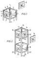
- Figure 1 is a perspective view of a basic structure which can be used as a basic building module,
- Figure 2 is a perspective view of an enlarged basic structure which can serve as a basic building module,
- Figure 3 is a similar view of an assembly of three enlarged modules forming a larger structure,
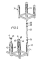
- Figure 4 is a perspective view illustrating how units of a decorative structure can be stacked one upon another or located in side-by-side relationship by means of the invention, and
- Figures 5 and 6 show additional decorative structures which may be incorporated in any linked or stacked structure by means of the invention.
- Figure 1 shows a basic module in the form of an open- topped tub -like structure for accommodating a plant pot. The structure has a framework (e.g. of steel, aluminium alloy or rigid plastics) having four legs 1 interconnected by four lateral members 2 surrounding a
square base panel 3. Instead of thepanel 3, a square ceramic tile with its glazed surface uppermost may be supported on ledges on the members 2. Above the members 2, the legs 1 havechannels 4 enabling squareceramic tiles 5 to be removably located, as indicated by the arrow in Figure 1, with their glazed surfaces outermost. Thechannels 4 may have a width to accommodate two ceramic tiles, the innermost tile of each pair then having its glazed surface facing inwardly. - Figure 2 illustrates a plant/tree support comprising four
upright legs 10 havingchannels 12 mounted on opposite faces of the legs between which rectangular glazedceramic tiles 14 are fitted. One of the tiles is shown removed at 16 to show the channel at 18 more clearly. - Between the
upright legs 10 are transversely extendingstruts 20 on which thetiles 14 rest. - The tiles can be lifted out if required for replacement.
- The interior of the structure is hollow and allows a tree to grow up therethrough.
- The lower ends of the legs extend downwardly to form
feet 22 by which the structure can be embedded in soil or concrete or the like surround/foundation. - Figure 3(in which like parts to those of Figure 3 bear the same reference numerals) shows how a structure such as that shown in Figure 2 can be extended to form a larger structure. As shown in Figure 3, the structures form a corner unit, the sides of which can be extended indefinitely if required to form walls, with or without further corner unit assemblies to provide for returns or to give extra support and rigidity.
- The extension of the sides may be by way of additional units such as shown in Figure 2, joining being effected by bolting through adjoining upright struts.
- Alternatively, extension kits may be provided comprising a pair of uprights joined by two transverse struts, two pairs of linking struts adapted to be secured between the uprights of the first structure and the extension pair and four pairs of channels adapted to be mounted on the opposed faces of the uprights joined by the linking struts. In this way, the uprights are limited to a single member each.
- In the structure of Figure 3, tiles need not, of course, be included in internal bridging "faces" of the structures although they have been shown.
- Where both inside and outside faces of tiles are visible, the channels are preferably made wider to accommodate two tiles arranged back to back, so that the glazed surfaces are visible and the unglazed surfaces hidden.
- Although described with reference to plant/tree supports, the structure may, of course, just comprise a free-standing screen such as may be used in a foyer or offices or on an exhibition stand or the like.
- Figure 4 is an exploded view illustrating how an
upper unit 31 of a decorative structure can be stacked upon alower unit 32.Legs respective units plastics plugs spacer tube 37 matching thelegs steel rod 38. - The
plugs spacer tube 37 andleg 34, respectively. Eachplug plugs spacer tube 37 and into the ends of thelegs spacer tube 37 forms, in effect, a portion of the vertical leg of the decorative structure. Other legs of the structure can be located one above another in a similar way, either with or withoutspacer tubes 37, giving a very versatile arrangement which can be adapted to suit the shape and size of decorative structure required. - Figure 4 also shows how two
vertical legs double plug 43, also of plastics material, having two spaced spigot-like formations for insertion in respective ends of thelegs plug 43 before insertion and B indicates theplug 43 after location on the upper ends of twoabutting legs 44 and 45 of the decorative structure. - Figures 5 and 6 illustrate additional decorative structures. In Figure 5 the structure is in the form of a window-box which can be made of any length and which can be used to interconnect units formed as columns or panels. The window box has
legs 51,lateral members 52,channel members 53 welded to thelegs 51, and reinforcingstrips 54 which are optional.Ceramic tiles 55 are detachably located between opposingchannel members 53. - Figure 6 shows a structure formed as a screen or panel which can be made of any width or height and which can be particularly useful to interconnect the columns shown in Figure 2. The screen has
legs 61,lateral members 62,channel members 63 welded to the legs and a reinforcing strip64 which is optional.Ceramic tiles 65 are detachably located betweenopposed channel members 63. - In all of the described structures the ceramic tiles are removable and can, therefore, be replaced to suit a change in decor. Also, the various structures can be connected one above another, or side by side, to provide a large variety of possible constructions of shape and size, offering a wide degree of versatility, without the need for bolts or screws.
- The rods 8 shown in Figure 4 may be fitted to extend upwardly from a unit (such as that shown in Figure 5) standing on a window ledge, the upper ends of the rods 8 being secured to the upper horizontal surface of the window reveal so that the rods serve as protection against burglary whilst being aesthetically more attractive than a metal grill because plants can climb up the rods 8.
- Adjacent units may be made so that they are hingedly connected together. The hinge pin could be a bar the upper end of which is pivoted within a short length of square-section tube attached to one unit, and the lower end of which is pivoted within a short length of square-section tube attached to the other unit. By making the square-section lengths to be similar to the legs of the units, the hinge would match the appearance of the remainder of the units.
- It will be appreciated that structures according to the invention are very versatile and may be made in heights, widths and depths to suit particular situations. Various modifications in the described structures are also possible. For example, the
bars 54 in Figure 5 are not essnetial because the remaining structure can be made sufficiently rigid. In the structure of Figure 3 no internal tiles are necessary, and castors can be added to the lower ends of the legs of any of the suitable structures to form a drinks trolley. The structure of Figure 1 could be made three, four, five or any number of tiles wide to make a unit suitable for standing on a window sill or table. In all cases, the tiles could be made of wood, aluminium alloy, metal, plastics or glass and the clips could be of any suitable material such as plastics or metal.
Claims (10)
1. A free-standing decorative structure comprising;
(1) an upright frame having at least three legs;
(2) intermediate struts which extend laterally between the legs;
(3) channels formed in, or carried by, opposed faces of at least two of the legs, and,
(4) at least one parallel sided panel having at least one decorative face removably fitted between the said two legs with the edges of the two parallel sides fitted in the channels in the opposed faces of the two legs, with the decorative face thereby facing outwardly.
2. A structure according to claim I wherein each said panel is a glazed ceramic tile.
3. A structure according to claim 2, wherein the frame is generally rectangular and has four upright legs and ceramic tiles are located between each of the pairs of legs with their opposite edges held in the channel associated with each pair of legs.
4. A structure according to claim 3, wherein the channels include obstructions at their lower ends to prevent each said file from falling therethrough.
5. A structure according to claim 3, wherein certain of the transverse struts serve as ledges for the panels and to this end are situated at, or near, the lower ends of the channels.
6. A structure according to claim 3, wherein the legs extend below the position of the lowest struts and constitute feet.
7. A structure according to claim 2, wherein a plurality of such structures form units adapted to be secured together, one above the other and/or side by side to form larger structures.
8. A structure according to claim 7, where the structure has locating members which locate in ends of the legs of the structure, each such locating member having a through-bore, and a plurality of rods for passing through the bores in the locating members and through the legs to enable the units to be stacked and located one upon another, the locating members being plugs having spigot-like formations for insertion into the ends of the legs, with the cross-sectional shape of the rods matching the cross-sectional shape of the bores in the plugs so that the rods fit snugly within the bores in the plugs.
9. A structure according to claim 8, wherein spacer tubes are provided to space one unit above another, the spacer tubes matching the legs so that the spacer tubes constitute portions of the lengths of the legs, with the rods passing not only through the plugs and the legs, but also the spacer tubes.
10. A structure according to claim 9, wherein further plugs are provided, to interconnect legs of the units in abutting side-by-side relationship, the further plugs having spaced lug-like formations for respective insertion into ends of the legs in order to attach the latter together.
Applications Claiming Priority (4)
| Application Number | Priority Date | Filing Date | Title |
|---|---|---|---|
| GB8135393 | 1981-11-24 | ||
| GB8135393 | 1981-11-24 | ||
| GB8201196 | 1982-01-16 | ||
| GB8201196 | 1982-01-16 |
Publications (2)
| Publication Number | Publication Date |
|---|---|
| EP0080252A2 true EP0080252A2 (en) | 1983-06-01 |
| EP0080252A3 EP0080252A3 (en) | 1984-02-29 |
Family
ID=26281361
Family Applications (1)
| Application Number | Title | Priority Date | Filing Date |
|---|---|---|---|
| EP82302856A Withdrawn EP0080252A3 (en) | 1981-11-24 | 1982-06-03 | Self-supporting decorative structure |
Country Status (2)
| Country | Link |
|---|---|
| EP (1) | EP0080252A3 (en) |
| GB (1) | GB2109838B (en) |
Cited By (7)
| Publication number | Priority date | Publication date | Assignee | Title |
|---|---|---|---|---|
| EP0374898A1 (en) * | 1988-12-21 | 1990-06-27 | Vivaria Gmbh Import Von Pflanzen Und Tieren | Plant table |
| FR2740181A1 (en) * | 1995-12-26 | 1997-04-25 | Treanton Olivier | Inter-locking furniture frame with decorative inserts |
| ES2132024A1 (en) * | 1997-06-11 | 1999-08-01 | Moidecar Sl | Dismantlable modular display device |
| ES2132022A1 (en) * | 1997-06-03 | 1999-08-01 | Moidecar Sl | Modular display device with rotary panels |
| FR2844221A1 (en) * | 2002-09-11 | 2004-03-12 | Beata Kowalska | Vase or lamp stand has glazed section attached by tongue and groove connection to cylindrical section |
| WO2004026085A1 (en) * | 2002-09-17 | 2004-04-01 | Heger Francois Marc | Covering device for plant pots |
| EP2003950A1 (en) * | 2006-04-10 | 2008-12-24 | Kim, Jung-hoi | Prefabrication type flowerpot block |
Families Citing this family (1)
| Publication number | Priority date | Publication date | Assignee | Title |
|---|---|---|---|---|
| PL440260A1 (en) * | 2022-01-31 | 2023-06-05 | Art Progres Polska Spółka Z Ograniczoną Odpowiedzialnością | Resilient composite plate and how to use it |
Citations (7)
| Publication number | Priority date | Publication date | Assignee | Title |
|---|---|---|---|---|
| FR724362A (en) * | 1931-09-15 | 1932-04-26 | Removable and multiple combination box, for plants and shrubs, and its embodiment | |
| DE1929652A1 (en) * | 1968-06-10 | 1969-12-11 | Gema Ag | Ceiling or wall cladding |
| CH514979A (en) * | 1971-04-02 | 1971-11-15 | Wolf Ag A | Planting tower |
| DE2540038A1 (en) * | 1975-09-09 | 1977-03-17 | Hansjuergen Broichmann | Sectional plant stand made of light concrete - has pedestal with socket holding vertical metal support for plant tubs interspersed with spacer rings |
| GB1470266A (en) * | 1974-10-17 | 1977-04-14 | Art & Media Ag | Modular plant unit |
| DE2555094A1 (en) * | 1975-12-08 | 1977-06-23 | Wolf Dieter Norra | Frame for mounting carved wooden panels - has undercut frame sides to provide tongue and groove joint for multiple wooden panels |
| DE2704414A1 (en) * | 1977-02-03 | 1978-09-14 | Albrecht Bruno Dr Rer Pol | Plant container of triangular profile - consists of water-collecting layer with plastics or glass fibre matting separating soil |
-
1982
- 1982-06-03 EP EP82302856A patent/EP0080252A3/en not_active Withdrawn
- 1982-06-03 GB GB08216222A patent/GB2109838B/en not_active Expired
Patent Citations (7)
| Publication number | Priority date | Publication date | Assignee | Title |
|---|---|---|---|---|
| FR724362A (en) * | 1931-09-15 | 1932-04-26 | Removable and multiple combination box, for plants and shrubs, and its embodiment | |
| DE1929652A1 (en) * | 1968-06-10 | 1969-12-11 | Gema Ag | Ceiling or wall cladding |
| CH514979A (en) * | 1971-04-02 | 1971-11-15 | Wolf Ag A | Planting tower |
| GB1470266A (en) * | 1974-10-17 | 1977-04-14 | Art & Media Ag | Modular plant unit |
| DE2540038A1 (en) * | 1975-09-09 | 1977-03-17 | Hansjuergen Broichmann | Sectional plant stand made of light concrete - has pedestal with socket holding vertical metal support for plant tubs interspersed with spacer rings |
| DE2555094A1 (en) * | 1975-12-08 | 1977-06-23 | Wolf Dieter Norra | Frame for mounting carved wooden panels - has undercut frame sides to provide tongue and groove joint for multiple wooden panels |
| DE2704414A1 (en) * | 1977-02-03 | 1978-09-14 | Albrecht Bruno Dr Rer Pol | Plant container of triangular profile - consists of water-collecting layer with plastics or glass fibre matting separating soil |
Cited By (10)
| Publication number | Priority date | Publication date | Assignee | Title |
|---|---|---|---|---|
| EP0374898A1 (en) * | 1988-12-21 | 1990-06-27 | Vivaria Gmbh Import Von Pflanzen Und Tieren | Plant table |
| US5099606A (en) * | 1988-12-21 | 1992-03-31 | Vivaria Gmbh | Plant-cultivation board |
| FR2740181A1 (en) * | 1995-12-26 | 1997-04-25 | Treanton Olivier | Inter-locking furniture frame with decorative inserts |
| ES2132022A1 (en) * | 1997-06-03 | 1999-08-01 | Moidecar Sl | Modular display device with rotary panels |
| ES2132024A1 (en) * | 1997-06-11 | 1999-08-01 | Moidecar Sl | Dismantlable modular display device |
| FR2844221A1 (en) * | 2002-09-11 | 2004-03-12 | Beata Kowalska | Vase or lamp stand has glazed section attached by tongue and groove connection to cylindrical section |
| WO2004026085A1 (en) * | 2002-09-17 | 2004-04-01 | Heger Francois Marc | Covering device for plant pots |
| EP2003950A1 (en) * | 2006-04-10 | 2008-12-24 | Kim, Jung-hoi | Prefabrication type flowerpot block |
| EP2003950A4 (en) * | 2006-04-10 | 2009-04-01 | Jung-Hoi Kim | Prefabrication type flowerpot block |
| CN101505585B (en) * | 2006-04-10 | 2011-06-22 | 金正会 | Prefabrication type flowerpot block |
Also Published As
| Publication number | Publication date |
|---|---|
| GB2109838B (en) | 1986-02-05 |
| GB2109838A (en) | 1983-06-08 |
| EP0080252A3 (en) | 1984-02-29 |
Similar Documents
| Publication | Publication Date | Title |
|---|---|---|
| JP5001148B2 (en) | Structures for walls where plants are planted | |
| KR20130008533A (en) | Reticulated stereo module for the construction of buildings, and construction method | |
| US20090293391A1 (en) | Partitions for cubicles | |
| US6513288B1 (en) | Window assembly for partitions | |
| JPH03244736A (en) | System for controlling operation space | |
| US5553551A (en) | Interlocking modular bench system | |
| EP1156178B1 (en) | Partition former for inhabitable spaces and use thereof | |
| EP0080252A2 (en) | Self-supporting decorative structure | |
| GB2485412A (en) | Slot together partition system | |
| IL151244A (en) | Panel for modular construction | |
| US3885675A (en) | Construction kit for the erection of storage and display structures of varying dimensions in the form of shelves, cupboards, display cases and the like | |
| US20020056835A1 (en) | Solid-appearing fence system | |
| GB2142057A (en) | Garden shed | |
| JP4034045B2 (en) | Exhibit prop support | |
| RU51466U1 (en) | RACK (OPTIONS) | |
| EP1452671B1 (en) | Screen element | |
| JPH07229220A (en) | Partitioning device | |
| EP0005901A2 (en) | Wall unit for use in the storage and/or display of articles, and structure incorporating such a unit | |
| JP2002161622A (en) | Fence | |
| RU59093U1 (en) | False Ceiling Design | |
| DE202016006632U1 (en) | Kit for exhibition purposes | |
| JP3459244B2 (en) | Small room structure for indoor installation | |
| CN217760365U (en) | Can dismantle construction enclosure for building engineering | |
| RU2183939C2 (en) | Sectional furniture unit | |
| CN210610442U (en) | Stable multilayer pergola |
Legal Events
| Date | Code | Title | Description |
|---|---|---|---|
| PUAI | Public reference made under article 153(3) epc to a published international application that has entered the european phase |
Free format text: ORIGINAL CODE: 0009012 |
|
| AK | Designated contracting states |
Designated state(s): BE DE FR GB IT NL |
|
| PUAL | Search report despatched |
Free format text: ORIGINAL CODE: 0009013 |
|
| AK | Designated contracting states |
Designated state(s): BE DE FR GB IT NL |
|
| 17P | Request for examination filed |
Effective date: 19840810 |
|
| STAA | Information on the status of an ep patent application or granted ep patent |
Free format text: STATUS: THE APPLICATION HAS BEEN WITHDRAWN |
|
| 18W | Application withdrawn |
Withdrawal date: 19850507 |