EP0077245A1 - Manipulator zum fernbedienbaren Eingreifen im Wasserbehälter eines Dampferzeugers - Google Patents
Manipulator zum fernbedienbaren Eingreifen im Wasserbehälter eines Dampferzeugers Download PDFInfo
- Publication number
- EP0077245A1 EP0077245A1 EP82401782A EP82401782A EP0077245A1 EP 0077245 A1 EP0077245 A1 EP 0077245A1 EP 82401782 A EP82401782 A EP 82401782A EP 82401782 A EP82401782 A EP 82401782A EP 0077245 A1 EP0077245 A1 EP 0077245A1
- Authority
- EP
- European Patent Office
- Prior art keywords
- arm
- clamps
- plate
- tube plate
- carrier block
- Prior art date
- Legal status (The legal status is an assumption and is not a legal conclusion. Google has not performed a legal analysis and makes no representation as to the accuracy of the status listed.)
- Granted
Links
Images

Classifications
-
- B—PERFORMING OPERATIONS; TRANSPORTING
- B25—HAND TOOLS; PORTABLE POWER-DRIVEN TOOLS; MANIPULATORS
- B25J—MANIPULATORS; CHAMBERS PROVIDED WITH MANIPULATION DEVICES
- B25J5/00—Manipulators mounted on wheels or on carriages
-
- F—MECHANICAL ENGINEERING; LIGHTING; HEATING; WEAPONS; BLASTING
- F22—STEAM GENERATION
- F22B—METHODS OF STEAM GENERATION; STEAM BOILERS
- F22B37/00—Component parts or details of steam boilers
- F22B37/002—Component parts or details of steam boilers specially adapted for nuclear steam generators, e.g. maintenance, repairing or inspecting equipment not otherwise provided for
- F22B37/003—Maintenance, repairing or inspecting equipment positioned in or via the headers
- F22B37/005—Positioning apparatus specially adapted therefor
Definitions
- the present invention relates to a remote manipulator more particularly intended to support and move the tools necessary for interventions inside a water box of a steam generator in a pressurized water nuclear power plant.
- the very large number of tubes in the tubular bundles of steam generators must be subject to periodic verification and maintenance operations, such as, for example, welding operations, fitting plugs. obturation to neutralize defective tubes, or interventions on the inner lining of the tubes.
- maintenance operations must be carried out from the water box, that is to say in a highly radioactive field; it is therefore necessary to use remote-controlled devices to limit human intervention to the simple installation of equipment.
- the steam generators are generally with vertical tubes, that is to say that the tube plate is then "at the ceiling" of the water box.
- each movement has phases during which the tool holder remains suspended from only two pliers, which greatly limits the weight of the tools that can be used.
- the present invention makes it possible to have a tele-manipulator device, both of greater capacity and more efficient, while reducing the interventions of personnel in a radioactive environment.
- the invention therefore relates to an intervention remote manipulator in a steam generator water box, intended to be fixed under the tubular plate of the generator, the device being of the type comprising expandable clamps for engaging and block on demand in holes in the tube plate, mounted on arms carried by a support block, with means for independently giving each arm, on the one hand, movements perpendicular to the plate to engage clamps in the holes or release them, and secondly stepwise movements parallel to the plate, thus allowing the autonomous movement of the device under the tubular plate while still hanging there by at least two clamps.
- the carrier block supports four independent arms each provided with two expandable clamps, and at its part opposite to the tubular plate, the carrier block supports an arm with several elements articulated between them, the extreme element of the arm being provided with means for fixing tools, and the whole of the arm itself being orientable around the axis of the block perpendicular to the tube plate;
- the device comprises remote-controlled means for adjusting and maintaining the angular position of the arm relative to the carrier block, and the relative angular position between them of each of the elements of the arm.
- the carrier block is constituted by a tubular frame with guide bars regularly distributed in groups of 2 around its axis, each arm being constituted by a carriage engaged on each. pair of bars, the clamps themselves being carried by a slide movable on the carriage perpendicular to the guide bars.
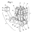
- the apparatus comprises a support block generally designated by 1, and provided with attachment clips 10 and means for moving these clips to ensure the movement of the device under the tube plate.
- Block 1 supports a mani- ? articulated ulator 2 which constitutes the actual tool holder.
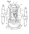
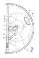
- the carrier block 1, more visible in Figures 2 and 3, is here constituted by a tubular frame 5 carrying at its ends two annular flanges 6 and 7.
- the flanges 6 and 7 are also connected by eight guide bars 8-9 regularly distributed in groups of two around the frame 5.
- the device is provided with eight expandable clamps 10, of the usual type and with positive security, that is to say that their expandable end is normally in the expanded position, therefore in the position clamping and hooking when it is engaged in one of the holes in the plate. It is by the controlled action of the built-in cylinder, pneumatic or electric, that the expandable part can be retracted to unhook the clamp; in case loss of pneumatic or electrical power, the device will therefore remain attached to the plate.
- a more complete description of such expandable clamps can be found in the French patent already cited 2,309,314.
- the block 1 comprises four identical sets, or arms, as shown in FIGS. 2 and 3. Each arm therefore carries two clamps 10 and is associated with a pair of bars 8-9.
- the arm comprises a sliding carriage 12 which can be moved along the bars 8-9, that is to say perpendicular to the tube plate when the device is in place.
- the slide 12 is simply engaged on the bar 8 which has only a guiding role.
- the bar 9 constitutes the rod on either side of a fixed piston 13o which slides in relative movement in a bore 14 of the slide 12.
- the bore 14 is closed at each end by a bottom 15, crossed by the bar 9, so that a double-acting cylinder with fixed piston has thus been formed, and the movable body of which is the slide 12 itself.
- the connections 16 allow the supply of one or the other chamber of the jack, and consequently the parallel movement of the slide along the bars 8 and 9.
- the two clamps 10 are fixed to the ends of a cross-member 18 which slides in a slide 19 formed on the front face of the slide 12, by the free space between two plates 20-21 secured to the slide 12.
- the cross-member 18 is held trapped in the slide 19 by the two supports 22 fixed on the plates 20, 21 and which span the crosspiece 18 without hindering its transverse movement.
- Each support 22 also forms one of the two bottoms of a double-acting cylinder, the body 24 of which contains a piston with two rods 25, 26 which pass through the supports 22.
- the total length of the assembly of the piston and of its rods 25- 26 is equal to the internal distance between the supports 27 of the clamps 10, so that the ends of the rods 25 and 26 are always in contact with the two supports 27.
- the connections 29 allow the supply of one or the other chamber of the actuator 24, which causes the transverse displacement of the assembly of the cross member 18 and of the two clamps 10 that it supports.
- the total stroke of the actuator 24 is equal to a pitch for installing the tubes on the tube plate, while of course the distance between the two clamps 10 is equal to an integer multiple of this pitch.
- the lower flange 7 supports a rotary crown 32 under which the assembly of the tool-carrying arm 2 pivots around the axis of the tubular frame 5.
- the arm 2 comprises a first element 33 forming a fork offset relative to the axis of rotation of the crown 32.
- a second element 34 is articulated at 35 out of 33.
- a third element 36 is similarly articulated at 37 on the other end of 34.
- a tool-carrying slide 38 is articulated at 39 at the other end of 36.
- the slide 38 is equipped with usual means for gripping and holding tools, means which are here (FIG. 1) simply symbolized by a groove 40.
- the axes of the articulations 35, 37 and 39 are mutually parallel and perpendicular to the axis of the frame 5.
- Each articulation, as well the articulations 35, 37 and 39 as that of the yoke 33 on the crown 32, is equipped with an internal angular positioning motor allowing, by a usual master-slave system, each element of the arm 2 to reproduce by remote control the displacements of the homologous elements of an arm maneuvered on a replica by an external operator.
- the sheath 42 groups all the circuits of this remote control.
- the device is particularly suitable for repetitive operations, such as the systematic sealing of tubes in a defective area. It is then possible, by means of the manipulator arm 2 to take the plugs one after the other through the hole 44 after having placed the previous one, and without having to move the carrier block 1 between each operation.
Applications Claiming Priority (2)
| Application Number | Priority Date | Filing Date | Title |
|---|---|---|---|
| FR8118669 | 1981-10-05 | ||
| FR8118669A FR2513927A1 (fr) | 1981-10-05 | 1981-10-05 | Tele-manipulateur d'intervention dans une boite a eau de generateur de vapeur |
Publications (2)
| Publication Number | Publication Date |
|---|---|
| EP0077245A1 true EP0077245A1 (de) | 1983-04-20 |
| EP0077245B1 EP0077245B1 (de) | 1984-11-21 |
Family
ID=9262723
Family Applications (1)
| Application Number | Title | Priority Date | Filing Date |
|---|---|---|---|
| EP82401782A Expired EP0077245B1 (de) | 1981-10-05 | 1982-09-30 | Manipulator zum fernbedienbaren Eingreifen im Wasserbehälter eines Dampferzeugers |
Country Status (10)
| Country | Link |
|---|---|
| US (1) | US4592691A (de) |
| EP (1) | EP0077245B1 (de) |
| JP (1) | JPS5877697A (de) |
| KR (1) | KR880001408B1 (de) |
| CA (1) | CA1203923A (de) |
| DE (1) | DE3261302D1 (de) |
| ES (1) | ES516186A0 (de) |
| FR (1) | FR2513927A1 (de) |
| YU (1) | YU44211B (de) |
| ZA (1) | ZA827015B (de) |
Cited By (2)
| Publication number | Priority date | Publication date | Assignee | Title |
|---|---|---|---|---|
| US4716010A (en) * | 1983-12-13 | 1987-12-29 | Westinghouse Electric Corp. | Tooling apparatus for modifying nuclear reactors |
| USRE33373E (en) * | 1983-12-13 | 1990-10-09 | Westinghouse Electric Corp. | Tooling apparatus for modifying nuclear reactors |
Families Citing this family (5)
| Publication number | Priority date | Publication date | Assignee | Title |
|---|---|---|---|---|
| FR2598209B1 (fr) * | 1986-04-30 | 1988-08-12 | Framatome Sa | Procede et dispositif de chemisage a distance d'un tube de generateur de vapeur d'un reacteur nucleaire a eau sous pression. |
| JPH0453914Y2 (de) * | 1986-09-16 | 1992-12-17 | ||
| TW463028B (en) * | 1998-04-21 | 2001-11-11 | Hitachi Shipbuilding Eng Co | Working robot for heat exchangers and operating method thereof |
| US7314343B2 (en) * | 2002-07-22 | 2008-01-01 | Westinghouse Electric Co. Llc | Miniature manipulator for servicing the interior of nuclear steam generator tubes |
| US8746089B2 (en) * | 2009-01-19 | 2014-06-10 | Babcock & Wilcox Nuclear Energy, Inc. | Apparatus for automated positioning of eddy current test probe |
Citations (6)
| Publication number | Priority date | Publication date | Assignee | Title |
|---|---|---|---|---|
| US3247979A (en) * | 1962-12-14 | 1966-04-26 | Programmed & Remote System Cor | Manipulator control system |
| US4018345A (en) * | 1975-11-18 | 1977-04-19 | Combustion Engineering, Inc. | Surface traversing apparatus |
| DE2912658A1 (de) * | 1978-04-24 | 1979-10-25 | Combustion Eng | Flaechenschreitvorrichtung |
| FR2431109A1 (fr) * | 1978-07-10 | 1980-02-08 | Kraftwerk Union Ag | Dispositif de controle pour un echangeur de chaleur |
| EP0020272A1 (de) * | 1979-05-31 | 1980-12-10 | Framatome | Beweglicher Gerätehalter für die Arbeit an einer Rohrplatte |
| EP0045454A2 (de) * | 1980-08-06 | 1982-02-10 | Kraftwerk Union Aktiengesellschaft | Manipulator zum Positionieren einer Rohrsonde |
Family Cites Families (1)
| Publication number | Priority date | Publication date | Assignee | Title |
|---|---|---|---|---|
| US4303368A (en) * | 1978-09-18 | 1981-12-01 | Westinghouse Electric Corp. | Remote docking apparatus |
-
1981
- 1981-10-05 FR FR8118669A patent/FR2513927A1/fr active Granted
-
1982
- 1982-09-24 ZA ZA827015A patent/ZA827015B/xx unknown
- 1982-09-27 US US06/424,771 patent/US4592691A/en not_active Expired - Fee Related
- 1982-09-30 YU YU2194/82A patent/YU44211B/xx unknown
- 1982-09-30 CA CA000412607A patent/CA1203923A/fr not_active Expired
- 1982-09-30 DE DE8282401782T patent/DE3261302D1/de not_active Expired
- 1982-09-30 EP EP82401782A patent/EP0077245B1/de not_active Expired
- 1982-10-04 JP JP57175240A patent/JPS5877697A/ja active Granted
- 1982-10-04 ES ES516186A patent/ES516186A0/es active Granted
- 1982-10-05 KR KR8204477A patent/KR880001408B1/ko active
Patent Citations (6)
| Publication number | Priority date | Publication date | Assignee | Title |
|---|---|---|---|---|
| US3247979A (en) * | 1962-12-14 | 1966-04-26 | Programmed & Remote System Cor | Manipulator control system |
| US4018345A (en) * | 1975-11-18 | 1977-04-19 | Combustion Engineering, Inc. | Surface traversing apparatus |
| DE2912658A1 (de) * | 1978-04-24 | 1979-10-25 | Combustion Eng | Flaechenschreitvorrichtung |
| FR2431109A1 (fr) * | 1978-07-10 | 1980-02-08 | Kraftwerk Union Ag | Dispositif de controle pour un echangeur de chaleur |
| EP0020272A1 (de) * | 1979-05-31 | 1980-12-10 | Framatome | Beweglicher Gerätehalter für die Arbeit an einer Rohrplatte |
| EP0045454A2 (de) * | 1980-08-06 | 1982-02-10 | Kraftwerk Union Aktiengesellschaft | Manipulator zum Positionieren einer Rohrsonde |
Cited By (2)
| Publication number | Priority date | Publication date | Assignee | Title |
|---|---|---|---|---|
| US4716010A (en) * | 1983-12-13 | 1987-12-29 | Westinghouse Electric Corp. | Tooling apparatus for modifying nuclear reactors |
| USRE33373E (en) * | 1983-12-13 | 1990-10-09 | Westinghouse Electric Corp. | Tooling apparatus for modifying nuclear reactors |
Also Published As
| Publication number | Publication date |
|---|---|
| KR840002087A (ko) | 1984-06-11 |
| EP0077245B1 (de) | 1984-11-21 |
| YU219482A (en) | 1986-04-30 |
| FR2513927B1 (de) | 1984-10-19 |
| ZA827015B (en) | 1983-07-27 |
| JPH0242200B2 (de) | 1990-09-20 |
| CA1203923A (fr) | 1986-04-29 |
| JPS5877697A (ja) | 1983-05-11 |
| ES8403353A1 (es) | 1984-03-16 |
| KR880001408B1 (ko) | 1988-08-01 |
| DE3261302D1 (en) | 1985-01-03 |
| US4592691A (en) | 1986-06-03 |
| FR2513927A1 (fr) | 1983-04-08 |
| ES516186A0 (es) | 1984-03-16 |
| YU44211B (en) | 1990-04-30 |
Similar Documents
| Publication | Publication Date | Title |
|---|---|---|
| CA1136390A (fr) | Porte-outil mobile pour travail sur une plaque tubulaire | |
| EP0040159B1 (de) | Manipulator | |
| EP1803996B1 (de) | Interventionsverfahren und Vorrichtung in einem Wasserkasten eines Wärmetauschers | |
| FR3029127B1 (fr) | Dispositif de chargement d'un outil de soudage de grille d'espacement | |
| EP0104118B1 (de) | Vorrichtung zum lösbaren Verbinden einer Greifvorrichtung an einem Manipulatorarm sowie zugehörige Auflage zum Lösen | |
| BE897645A (fr) | Appareil de saisie et de manipulation de pieces d'usinage pour systemes de soudage au laser et autres systemes analogues | |
| EP0077245B1 (de) | Manipulator zum fernbedienbaren Eingreifen im Wasserbehälter eines Dampferzeugers | |
| EP0388296A1 (de) | Interventionsvorrichtung, insbesondere zur Prüfung, Inspektion und Wartung von Wärmeaustauschern | |
| EP0030484B1 (de) | Sondenträgervorrichtung zum Überprüfen der Rohre eines Dampferzeugers | |
| CA1054808A (fr) | Dispositif pour enterrer des elements flexibles de grande longueur | |
| EP0063073B1 (de) | Vorrichtung zum Positionieren eines Gerätes in den Öffnungen einer Rohrplatte | |
| EP0194926A1 (de) | Mehrzweckroboter zum Behandeln der Innenwände von Behältern | |
| FR2770927A1 (fr) | Machine de chargement pour deplacer des objets oblongs etroitement voisins, notamment des assemblages combustibles | |
| FR2690554A1 (fr) | Dispositif et procédé de montage de crayons dans un squelette d'assemblage combustible nucléaire. | |
| EP1141967B1 (de) | Einrichtung zum beladen von brennstäben in ein kernreaktorbrennstabbündel | |
| FR2723661A1 (fr) | Installation pour la mise en place d'assemblages de combustible nucleaire | |
| CA1308497C (fr) | Systeme de decontamination des tuyauteries primaires et de la boite a eau d'un generateur de vapeur de centrale nucleaire | |
| FR2626515A1 (fr) | Vehicule concu pour se deplacer sur la plaque perforee d'un faisceau de tubes, pour positionner selectivement un outil au droit des tubes dudit faisceau | |
| EP0398792B1 (de) | Einrichtung zum Positionieren eines Gerätes in eine zylindrische Höhlung mit regelmässig geordneten Perforationen | |
| EP0463913A1 (de) | Automatische Fördervorrichtung für mehrere Positionier- oder Verbindungselemente | |
| EP0589792B1 (de) | Handhabungseinrichtung für Rohrbündel von Wärmetauschern | |
| EP0391778A1 (de) | Vorrichtung zum Zentrieren eines Interventionsgerät in einem Dampferzeugerrohr | |
| FR2577863A1 (fr) | Vehicule autonome poseur de pont pour breches de vingt a quarante metres | |
| FR3127325A1 (fr) | Système de démantèlement pour installation nucléaire et méthodes de prolongement et de raccourcissement du mât d’un tel système de démantèlement | |
| EP0142434A1 (de) | Autonome, integrierte Vorrichtung zur Herstellung von Bewehrungselementen, insbesondere für Stahlbeton |
Legal Events
| Date | Code | Title | Description |
|---|---|---|---|
| PUAI | Public reference made under article 153(3) epc to a published international application that has entered the european phase |
Free format text: ORIGINAL CODE: 0009012 |
|
| AK | Designated contracting states |
Designated state(s): BE CH DE FR GB IT LI SE |
|
| 17P | Request for examination filed |
Effective date: 19830329 |
|
| ITF | It: translation for a ep patent filed |
Owner name: JACOBACCI & PERANI S.P.A. |
|
| GRAA | (expected) grant |
Free format text: ORIGINAL CODE: 0009210 |
|
| AK | Designated contracting states |
Designated state(s): BE CH DE FR GB IT LI SE |
|
| REF | Corresponds to: |
Ref document number: 3261302 Country of ref document: DE Date of ref document: 19850103 |
|
| PLBE | No opposition filed within time limit |
Free format text: ORIGINAL CODE: 0009261 |
|
| STAA | Information on the status of an ep patent application or granted ep patent |
Free format text: STATUS: NO OPPOSITION FILED WITHIN TIME LIMIT |
|
| 26N | No opposition filed | ||
| PGFP | Annual fee paid to national office [announced via postgrant information from national office to epo] |
Ref country code: GB Payment date: 19920922 Year of fee payment: 11 |
|
| PGFP | Annual fee paid to national office [announced via postgrant information from national office to epo] |
Ref country code: BE Payment date: 19920923 Year of fee payment: 11 |
|
| PGFP | Annual fee paid to national office [announced via postgrant information from national office to epo] |
Ref country code: SE Payment date: 19920929 Year of fee payment: 11 Ref country code: FR Payment date: 19920929 Year of fee payment: 11 |
|
| ITTA | It: last paid annual fee | ||
| PGFP | Annual fee paid to national office [announced via postgrant information from national office to epo] |
Ref country code: CH Payment date: 19930816 Year of fee payment: 12 |
|
| PGFP | Annual fee paid to national office [announced via postgrant information from national office to epo] |
Ref country code: DE Payment date: 19930818 Year of fee payment: 12 |
|
| PG25 | Lapsed in a contracting state [announced via postgrant information from national office to epo] |
Ref country code: GB Effective date: 19930930 Ref country code: BE Effective date: 19930930 |
|
| PG25 | Lapsed in a contracting state [announced via postgrant information from national office to epo] |
Ref country code: SE Effective date: 19931001 |
|
| BERE | Be: lapsed |
Owner name: FRAMATOME ET CIE Effective date: 19930930 |
|
| GBPC | Gb: european patent ceased through non-payment of renewal fee |
Effective date: 19930930 |
|
| PG25 | Lapsed in a contracting state [announced via postgrant information from national office to epo] |
Ref country code: FR Free format text: LAPSE BECAUSE OF NON-PAYMENT OF DUE FEES Effective date: 19940531 |
|
| REG | Reference to a national code |
Ref country code: FR Ref legal event code: ST |
|
| PG25 | Lapsed in a contracting state [announced via postgrant information from national office to epo] |
Ref country code: LI Effective date: 19940930 Ref country code: CH Effective date: 19940930 |
|
| EUG | Se: european patent has lapsed |
Ref document number: 82401782.6 Effective date: 19940510 |
|
| REG | Reference to a national code |
Ref country code: CH Ref legal event code: PL |
|
| PG25 | Lapsed in a contracting state [announced via postgrant information from national office to epo] |
Ref country code: DE Effective date: 19950601 |