EP0076111A2 - Kupplungs- und Bremssystem zum Starten und Stoppen einer Leistungspresse - Google Patents
Kupplungs- und Bremssystem zum Starten und Stoppen einer Leistungspresse Download PDFInfo
- Publication number
- EP0076111A2 EP0076111A2 EP82305042A EP82305042A EP0076111A2 EP 0076111 A2 EP0076111 A2 EP 0076111A2 EP 82305042 A EP82305042 A EP 82305042A EP 82305042 A EP82305042 A EP 82305042A EP 0076111 A2 EP0076111 A2 EP 0076111A2
- Authority
- EP
- European Patent Office
- Prior art keywords
- brake
- clutch
- press
- drive shaft
- torque level
- Prior art date
- Legal status (The legal status is an assumption and is not a legal conclusion. Google has not performed a legal analysis and makes no representation as to the accuracy of the status listed.)
- Granted
Links
Images


Classifications
-
- B—PERFORMING OPERATIONS; TRANSPORTING
- B30—PRESSES
- B30B—PRESSES IN GENERAL
- B30B15/00—Details of, or accessories for, presses; Auxiliary measures in connection with pressing
- B30B15/10—Brakes specially adapted for presses
-
- B—PERFORMING OPERATIONS; TRANSPORTING
- B30—PRESSES
- B30B—PRESSES IN GENERAL
- B30B15/00—Details of, or accessories for, presses; Auxiliary measures in connection with pressing
- B30B15/12—Clutches specially adapted for presses
-
- B—PERFORMING OPERATIONS; TRANSPORTING
- B30—PRESSES
- B30B—PRESSES IN GENERAL
- B30B15/00—Details of, or accessories for, presses; Auxiliary measures in connection with pressing
- B30B15/14—Control arrangements for mechanically-driven presses
- B30B15/142—Control arrangements for mechanically-driven presses controlling the brake or the clutch
Definitions
- Power presses are generally started and stopped by means of pneumatically operated clutch and brake mechanisms, although mechanical and eddy current clutches and brakes are also used to some extent.
- the press is started by pneumatically disengaging the brake and pneumatically actuating the clutch to engage the press drive, after which the pneumatic pressure continues to increase to build up the desired full clutch torque.
- the press drive is accelerated at an extremely rapid rate.
- the pneumatic pressure on both the brake and the clutch must be dissipated, after which the brake is applied by means of mechanical spring pressure. Dissipation ofo,the pneumatic pressure sufficiently to engage the brake and disengage the clutch takes a long time, relative to the duration of one press cycle. In order to stop the press within a reasonable segment of a press cycle, therefore, the brake is normally applied with an extremely high force which stops the press rather abruptly after the clutch has been disengaged.
- the invention also provides an apparatus for starting and stopping a power press having a slide mechanism mounted for reciprocating movement, a press drive for cycling the slide mechanism, a clutch for connecting and disconnecting the press drive and the slide mechanism, and a brake for braking the press drive shaft, said apparatus being characterised by:
- Another advantage of such an improved system for starting and stopping a power press is that it minimizes the danger of damage to, and prolongs the operating life of, those portions of the press involved in, or controlled by, the automation system.
- Still another advantage of the invention is to provide an improved clutching and braking system which permits the brake to be applied at the same time that the clutch is being disengaged, thereby minimizing the stopping time and motion.
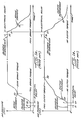
- the brake disengages at time t4.
- the brake remains disengaged until a solenoid is de-energized to stop the press, at time t6 in Figs. la and lb.
- This solenoid actuates a valve that exhausts the pneumatic pressure from both the clutch and the brake, but at a slower rate from the brake than from the clutch because the brake cannot be engaged until the clutch torque has been reduced to a certain level.
- the pneumatic pressure on both the brake and the clutch begins to diminish at the different rates.
- the brake is finally engaged at time t8, just slightly before the pneumatic pressure on the clutch drops sufficiently to disengage the clutch at time t9. Following engagement of the brake at time t8, the brake torque increases rapidly with a correspondingly rapid deceleration of the press drive shaft.
- the brake torque immediately drops to zero at time tll, and the clutch torque immediately increases to an intermediate torque level determined by one of two sources of hydraulic pressure for the clutch.
- the intermediate torque level is typically about 10% of full clutch torque.
- the clutch is maintained at this intermediate torque level for a preselected time interval, extending from time tll to time tl2 in Fig.2b, which is sufficient to bring the press drive shaft up to full speed.
- the hydraulic pressure on the clutch is increased to immediately raise the clutch torque to its full-on level, which is determined by the source of hydraulic pressure for the clutch.
- the hydraulic system provides a "soft" startup without any abrupt transitions or high acceleration rates which can upset the automation system and the workpiece handling mechanisms controlled thereby.
- the maximum acceleration force during startup with the system of Figs. 2a and 2b is only about one "g".
- Stopping the drive shaft with this intermediate level of brake torque provides a "soft" stop, i.e., the drive shaft is decelerated at a relatively slow and constant rate to avoid abrupt transitions of the type produced by the pneumatic system described above. Consequently, the hydraulic braking action does not disrupt the automation system or the workpiece handling mechanisms controlled thereby.
- the full hydraulic pressure is applied to the brake to produce full brake torque.
- the brake is then maintained at this full torque level until it is desired to start the press again.
- the two different torque levels for the hydraulic brake are determined by two sources of hydraulic pressure for the brake.
- the brake is connected to the first source, which sets the intermediate torque level, from time tl4 to time tl57 and then is switched to the second source, which sets the full-on torque level.
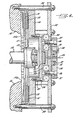
- the movable gripper ring 14 is advanced into its engaged position by means of hydraulic pressure supplied through a line 20 to a piston 21 slidably mounted in a primary cylinder plate 22.
- the hydraulic pressure moves the piston 21 to the left, as viewed in Fig.4, thereby advancing a pressure plate 23 which is rigidly connected to the movable gripper ring 14 by means of a plurality of bolts 24 and spacers 25.
- the hydraulic pressure is simply removed from the line 20.
- two circular arrays of compressed coil springs 30 and 31 are mounted in recesses formed in the surface of the primary cylinder plate 22 and mating recesses formed in the adjacent surface of a plate 32 which is rigidly fastened to the press frame by a plurality of bolts 33.
- the pressure of these springs 30 and 31 urges the cylinder plate 22 to the left as viewed in Fig.4, but such movement of the cylinder plate is prevented during normal operation of the brake by an over-riding hydraulic pressure. More specifically, hydraulic pressure is applied through a line 32 to an annular cylinder 33 formed by a secondary cylinder plate 34 and containing an annular piston 35.
- the two cylinder plates 22 and 34 are connected by a plurality of machine screws 36 passing through corresponding spacers 37, which in .-.turn pass through the fixed plate 32.
- the two cylinder plates 22 and 34 are linked together in a rigid assembly which can be moved back and forth relative to the fixed plate 32 which is disposed between the two cylinder plates to provide a stationary support for one end of the springs 30 and 31.
Landscapes
- Engineering & Computer Science (AREA)
- Mechanical Engineering (AREA)
- Control Of Presses (AREA)
- Braking Arrangements (AREA)
Applications Claiming Priority (2)
| Application Number | Priority Date | Filing Date | Title |
|---|---|---|---|
| US305839 | 1981-09-28 | ||
| US06/305,839 US4446785A (en) | 1981-09-28 | 1981-09-28 | Hydraulic clutching and braking system for starting and stopping a power press |
Publications (3)
| Publication Number | Publication Date |
|---|---|
| EP0076111A2 true EP0076111A2 (de) | 1983-04-06 |
| EP0076111A3 EP0076111A3 (en) | 1984-06-06 |
| EP0076111B1 EP0076111B1 (de) | 1987-08-12 |
Family
ID=23182586
Family Applications (1)
| Application Number | Title | Priority Date | Filing Date |
|---|---|---|---|
| EP82305042A Expired EP0076111B1 (de) | 1981-09-28 | 1982-09-24 | Kupplungs- und Bremssystem zum Starten und Stoppen einer Leistungspresse |
Country Status (10)
| Country | Link |
|---|---|
| US (1) | US4446785A (de) |
| EP (1) | EP0076111B1 (de) |
| JP (1) | JPS5868499A (de) |
| KR (1) | KR880000612B1 (de) |
| AR (1) | AR229057A1 (de) |
| AU (1) | AU8833082A (de) |
| BR (1) | BR8205641A (de) |
| CA (1) | CA1195175A (de) |
| DE (1) | DE3276933D1 (de) |
| ES (1) | ES8403380A1 (de) |
Cited By (1)
| Publication number | Priority date | Publication date | Assignee | Title |
|---|---|---|---|---|
| DE202014007305U1 (de) | 2014-09-08 | 2015-01-09 | Siempelkamp Maschinen- Und Anlagenbau Gmbh | Spindelpresse |
Families Citing this family (4)
| Publication number | Priority date | Publication date | Assignee | Title |
|---|---|---|---|---|
| ES2102289B1 (es) * | 1992-12-02 | 1998-01-16 | Coop Goizper S | Freno-embrague neumatico mejorado. |
| US6006660A (en) * | 1998-08-12 | 1999-12-28 | The Minster Machine Company | Segmented drive disk for a mechanical press |
| JP2010158718A (ja) * | 2008-12-08 | 2010-07-22 | Sumitomo Heavy Industries Techno-Fort Co Ltd | 湿式クラッチブレーキの油圧制御装置 |
| JP5091928B2 (ja) * | 2009-08-10 | 2012-12-05 | 住友重機械テクノフォート株式会社 | 機械プレスのクラッチブレーキ制御装置 |
Family Cites Families (14)
| Publication number | Priority date | Publication date | Assignee | Title |
|---|---|---|---|---|
| DE717082C (de) * | 1939-07-28 | 1942-02-05 | Miag Muehlenbau Und Ind Ag | Hydraulisch gesteuerte Bremsekupplung |
| US2436968A (en) * | 1945-07-31 | 1948-03-02 | Cleveland Punch & Shear Works | Combined clutch and brake |
| US2577641A (en) * | 1950-05-05 | 1951-12-04 | Minster Machine Co | Multiple drive press with multiple clutch |
| US2905290A (en) * | 1954-05-25 | 1959-09-22 | Niagara Machine & Tool Works | Clutch brake sequence control for power presses and the like |
| US2838150A (en) * | 1954-10-29 | 1958-06-10 | Ind Clutch Corp | Interconnected clutch and brake mechanism |
| GB804482A (en) * | 1955-12-05 | 1958-11-19 | Eumuco Ag Fur Maschb | An improved torque transmission device for use in presses and other workshop machinery |
| US3000478A (en) * | 1959-07-16 | 1961-09-19 | Ferracute Machine Company | Clutch-brake mechanism |
| US3224538A (en) * | 1963-06-20 | 1965-12-21 | William E Ward | Clutch unit for power press |
| DE1502319A1 (de) * | 1965-01-05 | 1969-04-10 | Schuler Gmbh L | Pressenkupplung |
| US3371759A (en) * | 1967-02-07 | 1968-03-05 | Bliss E W Co | Clutch control for mechanical devices |
| US3580371A (en) * | 1969-10-16 | 1971-05-25 | King Of Prussia Research & Dev | Self-synchronizing clutch |
| DE2412195A1 (de) * | 1974-03-14 | 1975-09-18 | Ortlinghaus Werke Gmbh | Hydraulisch schaltbare kupplungsbremsvorrichtung |
| GB1491203A (en) * | 1974-10-21 | 1977-11-09 | Volvo Ab | Devices for limiting torsional shocks |
| JPS5434952A (en) * | 1977-08-23 | 1979-03-14 | Redei Kk | Shoes making method |
-
1981
- 1981-09-28 US US06/305,839 patent/US4446785A/en not_active Expired - Fee Related
-
1982
- 1982-09-01 CA CA000410599A patent/CA1195175A/en not_active Expired
- 1982-09-13 AU AU88330/82A patent/AU8833082A/en not_active Abandoned
- 1982-09-15 KR KR8204186A patent/KR880000612B1/ko not_active Expired
- 1982-09-24 DE DE8282305042T patent/DE3276933D1/de not_active Expired
- 1982-09-24 EP EP82305042A patent/EP0076111B1/de not_active Expired
- 1982-09-27 BR BR8205641A patent/BR8205641A/pt not_active IP Right Cessation
- 1982-09-28 JP JP57169462A patent/JPS5868499A/ja active Pending
- 1982-09-28 ES ES516011A patent/ES8403380A1/es not_active Expired
- 1982-09-28 AR AR290797A patent/AR229057A1/es active
Cited By (1)
| Publication number | Priority date | Publication date | Assignee | Title |
|---|---|---|---|---|
| DE202014007305U1 (de) | 2014-09-08 | 2015-01-09 | Siempelkamp Maschinen- Und Anlagenbau Gmbh | Spindelpresse |
Also Published As
| Publication number | Publication date |
|---|---|
| ES516011A0 (es) | 1984-03-16 |
| AU8833082A (en) | 1983-04-14 |
| US4446785A (en) | 1984-05-08 |
| BR8205641A (pt) | 1983-08-30 |
| AR229057A1 (es) | 1983-05-31 |
| KR840001477A (ko) | 1984-05-07 |
| DE3276933D1 (en) | 1987-09-17 |
| EP0076111B1 (de) | 1987-08-12 |
| ES8403380A1 (es) | 1984-03-16 |
| JPS5868499A (ja) | 1983-04-23 |
| CA1195175A (en) | 1985-10-15 |
| KR880000612B1 (ko) | 1988-04-18 |
| EP0076111A3 (en) | 1984-06-06 |
Similar Documents
| Publication | Publication Date | Title |
|---|---|---|
| US6250434B1 (en) | Wear adjusting device for disk brakes and method for controlling the device | |
| GB2140107A (en) | Electric actuators | |
| CN109050497B (zh) | 一种汽车刹车装置 | |
| US4108295A (en) | Inertia-brake control for input shaft of gear box, and its application to clutches and units formed by a clutch and a gear-box | |
| US4446785A (en) | Hydraulic clutching and braking system for starting and stopping a power press | |
| EP0040027A1 (de) | Scheibenbremsen | |
| EP0110637B1 (de) | Scheibenbremsen für Fahrzeuge | |
| US4030577A (en) | Negative disc brake with a clearance-takeup mechanism | |
| KR100284445B1 (ko) | 구동 유니트용 전환장치 | |
| EP0848790B1 (de) | Pressantrieb mit kupplungs-bremsantrieb mit hydraulischer scherung | |
| US2890773A (en) | Clutch-brake mechanism | |
| GB2271622A (en) | Clutch/brake apparatus reduces torque on brake engagement | |
| GB1293822A (en) | Electromagnetic brake or clutch devices | |
| CN110979642B (zh) | 电刹车装置的释放机构及其使用方法 | |
| US3946838A (en) | Fail-safe disc brake | |
| US2472697A (en) | Automatically adjustable disk brake | |
| US4546860A (en) | Brake actuator device with automatic slack adjuster | |
| GB1427521A (en) | Shoe drum brakes for vehicles | |
| US4345123A (en) | Self-adjusting brake engine limit switch assembly | |
| US3092228A (en) | Power presses and other similar machine tools | |
| US12397767B2 (en) | Disc brake | |
| JP2510344B2 (ja) | 自動変速機のバンドブレ―キ | |
| RU2193971C2 (ru) | Винтовой пресс | |
| US2864481A (en) | Clutch with adjusting means | |
| JP2010131657A (ja) | サーボプレスの非常停止方法およびサーボプレス |
Legal Events
| Date | Code | Title | Description |
|---|---|---|---|
| PUAI | Public reference made under article 153(3) epc to a published international application that has entered the european phase |
Free format text: ORIGINAL CODE: 0009012 |
|
| AK | Designated contracting states |
Designated state(s): DE FR GB IT |
|
| PUAL | Search report despatched |
Free format text: ORIGINAL CODE: 0009013 |
|
| AK | Designated contracting states |
Designated state(s): DE FR GB IT |
|
| 17P | Request for examination filed |
Effective date: 19841122 |
|
| GRAA | (expected) grant |
Free format text: ORIGINAL CODE: 0009210 |
|
| AK | Designated contracting states |
Kind code of ref document: B1 Designated state(s): DE FR GB IT |
|
| REF | Corresponds to: |
Ref document number: 3276933 Country of ref document: DE Date of ref document: 19870917 |
|
| ITF | It: translation for a ep patent filed | ||
| ET | Fr: translation filed | ||
| PLBE | No opposition filed within time limit |
Free format text: ORIGINAL CODE: 0009261 |
|
| STAA | Information on the status of an ep patent application or granted ep patent |
Free format text: STATUS: NO OPPOSITION FILED WITHIN TIME LIMIT |
|
| ITPR | It: changes in ownership of a european patent |
Owner name: CESSIONE;AVONDALE INDUSTRIES INC. |
|
| ITPR | It: changes in ownership of a european patent |
Owner name: CESSIONE;CONNELL INDUSTRIES INC. |
|
| 26N | No opposition filed | ||
| REG | Reference to a national code |
Ref country code: FR Ref legal event code: TP |
|
| PGFP | Annual fee paid to national office [announced via postgrant information from national office to epo] |
Ref country code: GB Payment date: 19900803 Year of fee payment: 9 |
|
| PGFP | Annual fee paid to national office [announced via postgrant information from national office to epo] |
Ref country code: FR Payment date: 19900919 Year of fee payment: 9 |
|
| ITTA | It: last paid annual fee | ||
| PGFP | Annual fee paid to national office [announced via postgrant information from national office to epo] |
Ref country code: DE Payment date: 19901031 Year of fee payment: 9 |
|
| PG25 | Lapsed in a contracting state [announced via postgrant information from national office to epo] |
Ref country code: GB Effective date: 19910924 |
|
| GBPC | Gb: european patent ceased through non-payment of renewal fee | ||
| PG25 | Lapsed in a contracting state [announced via postgrant information from national office to epo] |
Ref country code: FR Effective date: 19920529 |
|
| PG25 | Lapsed in a contracting state [announced via postgrant information from national office to epo] |
Ref country code: DE Effective date: 19920602 |
|
| REG | Reference to a national code |
Ref country code: FR Ref legal event code: ST |
|
| ITPR | It: changes in ownership of a european patent |
Owner name: CESSIONE;DANLY - KOMATSU L.P. |