EP0075666A2 - Steuerschaltung für Blasenspeicher - Google Patents
Steuerschaltung für Blasenspeicher Download PDFInfo
- Publication number
- EP0075666A2 EP0075666A2 EP82106256A EP82106256A EP0075666A2 EP 0075666 A2 EP0075666 A2 EP 0075666A2 EP 82106256 A EP82106256 A EP 82106256A EP 82106256 A EP82106256 A EP 82106256A EP 0075666 A2 EP0075666 A2 EP 0075666A2
- Authority
- EP
- European Patent Office
- Prior art keywords
- data
- magnetic bubble
- signal
- control
- signals
- Prior art date
- Legal status (The legal status is an assumption and is not a legal conclusion. Google has not performed a legal analysis and makes no representation as to the accuracy of the status listed.)
- Granted
Links
Images

Classifications
-
- G—PHYSICS
- G06—COMPUTING OR CALCULATING; COUNTING
- G06F—ELECTRIC DIGITAL DATA PROCESSING
- G06F3/00—Input arrangements for transferring data to be processed into a form capable of being handled by the computer; Output arrangements for transferring data from processing unit to output unit, e.g. interface arrangements
- G06F3/007—Digital input from or digital output to memories of the shift register type
-
- G—PHYSICS
- G06—COMPUTING OR CALCULATING; COUNTING
- G06F—ELECTRIC DIGITAL DATA PROCESSING
- G06F13/00—Interconnection of, or transfer of information or other signals between, memories, input/output devices or central processing units
- G06F13/14—Handling requests for interconnection or transfer
- G06F13/20—Handling requests for interconnection or transfer for access to input/output bus
- G06F13/28—Handling requests for interconnection or transfer for access to input/output bus using burst mode transfer, e.g. direct memory access DMA, cycle steal
- G06F13/285—Halt processor DMA
Definitions
- the invention relates to data storage devices such as magnetic bubble memories that do not allow direct access to a desired stored word and, more specifically, to a control arrangement for coordinating data operations respective of such devices.
- Control arrangements for data storage devices that do not provide for direct word access serve in coordinating the multiple basic storage operations that are involved in executing the data storage requests initiated by an associated system.
- a request for the data word at a specified storage address typically involves a series of basic operations to advance, replicate and detect the stored information that is to be accessed.
- Circulation of stored information in minor loops is typically required to advance data to a site where a replication occurs to place corresponding data on a channel at which a read operation may be performed.
- the read operation is effected when the data is shifted to a detection site on the channel.
- a controller is often used which includes discrete logic designed specifically for supplying control signals that serve to coordinate basic storage maneuvers.
- a further approach uses a microprocessor to control the basic operations but a high performance microprocessor typically becomes necessary to generate the control signals at rates sufficient to utilize the storage efficiently. Furthermore, the microprocessor usually is dedicated to the single purpose of storage control.
- the processor In a system that includes a main processor, a direct access, read/write storage (RAM) and a magnetic bubble memory (MBM), the processor translates each gross storage operation with the MBM (e.g. a word store or word retrieve operation) to a customized string of special digital command words that serve to identify basic MBM bubble maneuvers (e.g. generate, swap, advance, replicate, detect).
- MBM magnetic bubble memory
- the command words of a string are stored in a section of the RAM.
- a direct memory access (DMA) device is then caused by the processor to transfer the command word string to an interface for the MBM that latches the command words one at a time and, effectively, decodes them to provide control signals to basic operation activating apparatus associated with the MBM.
- DMA direct memory access
- the processor can customize detailed sequences of basic operations while interacting at high speed with a direct-access storage and then assume normal processing functions while a DMA device coordinates the transfer of the coded commands to an interface to the storage.
- the interface then latches the commands individually and interprets them to issue individual control signals to the activating apparatus of the MBM.
- the processor also provides for bad data loops by initially reading redundancy information from a special loop having independent replication structures and then characterizing all other bits read as good or bad, in accordance with a stored table of the bad loop data located in RAM, using one bit of the command word.
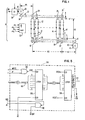
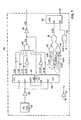
- a typical magnetic bubble memory 8 includes one or more paths such as the data loops 10 in which individual bubbles 12 may advance incrementally while retaining a stream position.
- the state of a stored information bit is indicated by the presence or absence of a bubble 12 at a particular elemental stream position for a loop 10 and a special loop 10' is provided that includes information identifying bad data loops and reference position (or element) for the streams of bubbles on the loops 10 and 10'.
- the reference position permits relative addressing to be recognized on the bubble stream.
- the bubbles 12 are generated in response to an input data signal DI at a generator structure 14 located along a write path or channel 16 at a generation or write site 18.
- the bubbles are advanced a fixed number (Nl) of locations along the channel 16 to arrive at fixed number (N2) of swap site locations adjacent the loops 10 and 10'.
- N2 fixed number of swap site locations adjacent the loops 10 and 10'.
- a transfer of bubbles 12 to loops 10 is effected in response to a signal S by "swap" structures 20 located at the respective loops 10.
- a separate swap structure 20' is provided to allow transfers of data to the loop 10' under the control of a signal S'.
- the loop 10' would be loaded with bad loop information and reference position information as a preliminary operation and left unchanged thereafter.
- the bad loop information allows the use of devices that have some loop defects by providing for avoidance of defective loops.
- Replications from the loops 10 to provide corresponding bubbles 12 in a read channel 22 are effected by replicate structures 24 (located at replicate sites or locations of the loops 10) in response to the signal R.
- a transfer of bad data loop information from the loop 10' to the read channel 22 may be effected at the separate replicate structure 24' in response to the signal R'.
- a fixed number of locations (N4) is provided beyond the loops 10 on the read channel 22 to arrive at a read site 26 at which a bubble detector (D) 28 is located.
- the signal DD produced by the bubble detector 28 is amplified by a sense amplifier (SA) 30 which is enabled by a signal E and produces an output signal BD indicative of stored information.
- SA sense amplifier
- Operation of the magnetic bubble memory 8 involves incremental circulation of the bubble streams in the loops 10 and on the channels 16 and 22 with increments of advance being stimulated by a set of coils 32 activated by four distinct phase signals ( ⁇ 1 ' ⁇ 2 1 ⁇ 3 ' ⁇ 4 ).
- Storage addresses may be recognized by establishing reference points on the bubble streams for the loops 10 and these sites may be identified, for example, using a special code, (e.g. a long string of empty bubble stream positions followed by one or more bubbles) included on the loop 10' along with the bad loop information.
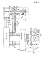
- a computer system 100 is connected to define address, data and control busses 102, 104 and 106, respectively, for transfer of signals.
- the busses 102, 104 and 106 carry signals between a processor 108, a read-only- storage (ROS) 110 and a direct-access read/write storage (RAM) 112 as is a well known configuration for digital signal processing.
- a direct memory access (DMA) device 114 is connected to the busses 102, 104 and 106 and interacts with a storage interface 115 using request and acknowledge lines 116 as is discussed in more detail below.
- DMA direct memory access
- the DMA device 114 may take various known forms and serves to respond to a request from the processor 108 to produce a sequence of data addresses on the address bus 102 along with data transfer control signals on the control bus 106 that permit direct data transfers to occur over the data bus 104.
- the processor 108 preferably transfers to the DMA device 114 a start address code, a code indicating the number of records to be transferred, identification codes for the devices selected to participate in the transfer, and a control signal defining the direction of transfer.
- Time on the busses 102, 104 and 106 for individual command word transfers is allocated to the DMA 114 by the processor 108 using hold and hold acknowledge lines 118 and 120 extending therebetween and a completion of transfers for a string of command words is signaled over an interrupt line 122.
- the processor 108 loads coded words representing basic storage operation commands into a command section 124 of the RAM 112 and these commands are transferred, preferably individually, to the storage interface 115 as coordinated by request and acknowledge signals Rl and Al transmitted over the lines 116.
- the storage interface 115 serves to latch command words transmitted from the RAM 112 and applies corresponding logic signals on line 132 to a function timing generator 130 for initiating basic storage operations.
- the function timing generator 130 is a part of means 132' for activating the magnetic bubble memory 8 to perform basic storage operations and provides timing signals to a coil driver (CD) 134, a write function driver (WFD) 136, a read function driver (RFD) 138 and the sense amplifier (SA) 30.
- Phase signals ⁇ 1 - ⁇ 4 for the coils 32 are generated by the coil driver 134 to cause advance of the bubbles 12.
- the write function driver 136 serves to apply the signal DI to the generator structure 14 when a bubble is requested to be formed and produces signals S and S' to cause swapping of bubbles from the write channel 16 to adjacent write sites on the loops 10 and to the loop 10 1 , respectively.
- the data of interest is advanced on the loops 10 to a read site at the replicate structures 24 or 24'.
- a replication of the loop states (bubble or no bubble) is effected onto the read channel 22 when the read function generator 138 applies a signal R or R' to the replicate structures 24 or 24', respectively.
- an enable signal E is sent to the sense amplifier 30.
- the signal E enables the sense amplifier 30 to respond to a characteristic (e.g. impedance) of detector 28 and produce the signal BD, indicating the state of the accessed data.
- the interface 115 further serves to receive the signal BD and cooperates with the DMA 114 to write requested data as coordinated by a second DMA channel and the request and acknowledge signals R2 and A2.
- the function timing generator 130 is a device known in the art and provides timed signals within the framework of an operating period (e.g. a ten microsecond operating period). Specific timing requirements are dictated by the magnetic bubble memory and one compatable family of devices suitable for practicing the invention includes the Texas Instruments, Inc. TIB0500 magnetic bubble memory module which may be used with function timing generator TI74LS772, sense amplifier 75282, read function driver 75393, write function driver 75392 and coil drivers 75388a.
- the storage interface 115 can be thought of as including a buffer 150, a storage command processing circuit 154, a timing circuit 156, and an accessed data converter 158.
- the buffer 150 serves to isolate the magnetic bubble memory 8 from the signal lines of the computer system 100 (see also Fig. 2) to guard against noise transmission.
- data from bus 104 is sent over lines 152 to storage command processing circuitry 154 that serves, as is discussed below, to latch the data bits for use as individual control signals.
- Timing signals for coordinating the data operations occurring within the storage interface 115 are produced by the timing circuit 156.
- Accessed data in the form of the signal BD from the sense amplifier #) is converted from serial to parallel form for transfer to the data bus 104 as is discussed more fully below.
- the buffer 150 includes a series of AND gates 200 that serve to provide noise isolation for various control signals such as the request signals Rl, R2 that are transmitted to the DMA device 114.
- the signals on lines 152 and 160 are isolated from the system 100 by a three-state bus buffer @)@ that connects to the data bus 104.
- a signal is applied from an AND gate 206 which receives the DMA acknowledge signals Al and A2.
- the signal ERD is applied to indicate intervals when data is to be read from the accessed data converter 150, as is discussed below.
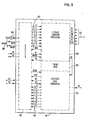
- the presently preferred storage command processor 154 of the interface 115 includes a first latch 300 that receives coded commands from the buffer 150 over the lines 152 and is clocked by the signal LOAD (see Fig. 8) produced by NAND gate 302 which receives the control signal, WRITE and the DMA acknowledge signal Al. Effectively, when both the signal WRITE and the signal Al are high, the latch 300 retains the levels asserted at lines 152. The latch 300 is cleared by the DMA request signal Rl (discussed below).
- Data from the latch 300 is sent to a second latch 308, under clocking control of the signal XFER (discussed below), which identifies an interval at the end of an operating cycle when the output of latch 300 is stable.
- the latch 308 supplies the data bits 0-5 as individual control signals to the function timing generator 130 over the lines 132.
- the 4-bit from the latch 308 corresponds to a coil enable signal CE for triggering a bubble advance and the 0-bit corresponds to a sense amplifier enable signal SE that triggers the enabling of the sense amplifier 30 to read data.
- the 2-bit preferably initiates a swap operation (SW) and the 3-bit a replicate operation (RE).
- SW swap operation
- RE replicate operation
- GE generate operation
- 6-bit serves to indicate if replicate and/or swap signals are intended for the loop 10 1 or the loops 10 (see Fig. 1).
- the 5-bit (GD) preferably indicates whether data at the read site is from one of the good loops of the set of loops 10.
- Clearing of the latch 308 is effected by the signal RESET that originates from a system power on reset (not shown).
- a signal RDY is generated from the DMA acknowledge signal Al and the signal 64 CNT (see Fig. 8) at a NAND gate 310.
- the RDY signal serves to prevent the DMA 114 from completing the data transfer on data bus 104 until the latch 308 has captured the coded command.
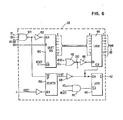
- the accessed data converter 158 (shown reversed left-to-right from Fig. 3) includes a shift register 400 that receives the signal BD from the sense amplifier 30 (see Fig. 2).
- a clocking signal for shift register 400 is produced by inverting, at an inverter 402, the output of a NAND gate 404 that has as inputs the signals SE which indicates the sense amplifier is enabled, GD which indicates the data is from a good loop, and 64 CNT which identifies a last portion of a memory cycle at which the output of the sense amplifier 30 is stable. Clearing of the shift register 400 occurs under control of the signal RESET which originates from the system power on reset.
- the output of the NAND gate 404 is also applied to a counter 406 that counts the bits accumulated in the shift register 400 and provides an output logic signal 8BIT at a count of eight.
- the inverse of the signal 8BIT is produced by an inverter 408 and serves to clock a latch 410 that produces the request R2 for the DMA device 114.
- the signal R2 hence, serves to indicate that a word of data is ready for transfer to the RAM 112. Clearing of the latch 410 is effected by a signal from an AND gate 412 that receives the acknowledge signal A2 and the signal RESET.
- the signal A2 and the control signal READ are applied at a NOR gate 418 to produce a signal ERD which is inverted at inverter 416 for application at the enable terminal of a latch 414 which captures the output of the shift register 400.
- the latch 414 is cleared by the output of the inverter 408 and serves to hold an eight bit word of data accumulated at the shift register 400 for transfer to the system 100 under the control of the DMA device 114.
- the presently preferred timing circuit 156 of the storage interface 115 serves to produce the signal XFER and the request signal Rl for the DMA device 114 (see also Fig. 2), which signals coordinate transfers of command signals from the RAM 112.
- a signal from a four megahertz oscillator 500 is inverted by an inverter 502 which serves as a buffer.
- the inverted signal is applied to first and second counters 504 and 506. These counters are connected to count up to sixty four of the oscillations from the oscillator 500 and outputs are provided (2 cnt, 4 cnt, 8 cnt, 16 cnt, 32 cnt and 64 cnt) for the binary digits of the count total.
- a NAND gate 508 and an inverter 510 are connected in series and provide the signal XFER when the count total is at seventy- eight compared to an eighty total for a 10 microsecond storage period.
- the latch 414 (Fig. 6) has a settled output representing a transferred command word and can be relied on during a latching operation.
- the output of the NAND gate 508 is used to clear the counters 504 and 506.
- the output signals of the counters 504 and 506 are also used to produce the signal DSET and the DMA request signal Rl (see Fig. 8) using NOR gates 512 and 514 in conjunction with an AND gate 516 to respond to a count of eighty.
- the DSET signal is latched to produce the signal Rl by a latch 518 that is cleared by the output signal of an AND gate 520 which receives the RESET signal and the signal Al as inputs.
- the inverter 522 is used to generate a logic one signal Ll.
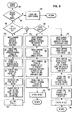
- command string generating logic for carrying out operation of processor 108 may be structured into a section 600 of the ROS 110 (see also Fig. 2).
- the incidence of a storage access request causes entry of a storage access subroutine (block 700) and a test is performed (block 702) to determine if the storage access request relates to an address in an address range assigned to the magnetic bubble memory 8. If not, a transfer to logic for other storage occurs (block 704). Otherwise, a transfer occurs to a test of a flag INIT (block 706) that is set to zero when the system 100 is powered up to indicate an initialization of the magnetic bubble memory has not taken place. If no initialization has taken place, the processor 108 proceeds to write a string of command words (block 708) into the RAM 112 at section 124 to cause reading of the special loop 10' that includes bad loop and reference point information.
- the command word bits have the significance indicated in Table 1, then a series of codes 1 1 0 1 1 0 0 0 is written to cause replication of redundancy loop 10' and advance the data stream on read channel 22 to the read position 26. Once the read position is reached (after N 2 + N4 command words), the code is changed to 0 1 1 1 1 0 0 1 to cause both replication and reading of data. Finally, when the full loop is replicated, the command word can be changed to 0 0 1 1 1 0 0 0 1 to read the data stream from the channel 22.
- the processor 108 enables (block 710) the DMA device 114 to transfer the string to interface 115.
- the data generated in responding to the command string is transferred to a data section 602 of the RAM 112 by enabling (block 712) a second channel of the DMA device 114.
- the processor examines (block 714) the data at section 602 of RAM 112 to identify a special code identifying the reference point of the data stream for loop 10' (which identifies also corresponding points on the loop 10).
- the number of bubble stream advances is determined, for example, from the length of the data set at the section 602 of the RAM 112 to provide an offset number representing the shift of the reference point from the replicate site.
- the offset number is stored in a location 604 of the RAM 12 (block 716).
- the bad loop table is stored in a section 606 of the R AM 112. With the initialization completed, the initialization flag is set (block 720) to permit subsequent transfer around the initialization logic and the logic transfers to branch point A.
- a test is entered to determine whether a read or write operation is intended (block 722). If a write operation is intended, the logic flow transfers to a series of processing steps (blocks 724-732) for writing data to a selected set of addresses. First, a command word string is written (block 724) to the section 124 of the RAM 112 for moving the addressed data receiving bubble stream positions Nl locations ahead of the write sites (using command words with data bit 4 at logic 1).
- a command string is then written (block 726) that generates bubbles in accordance with the data to be stored using commands of the form 0 0 0 1 0 0 X 0 (where the X represents a bit that is 0 or 1 according to the data).
- a "padding" command is included for positions corresponding to bad data loops as determined from the table stored in section 606 of the RAM 112.
- a command string is then written (block 728) to shift the bubbles in the channel 16 to meet the addressed bubble stream positions at the swap sites using commands with bit 4 at logic 1 and a swap operation is commanded using a command with bit 2 at logic 1 and bit 6 at logic 0.
- the DMA device 114 With the command string in place in section 124 of the RAM 112, the DMA device 114 is enabled to effect the transfers to the interface 115 for processing thereby as was discussed above.
- the offset is updated (block 732) based on the total of the bubble stream shifts that were commanded to write data.
- the bit 5 is set to logic 1 for good data and logic zero for bad loop data as determined from the bad loop table of section 606 of the RAM 112. It should be noted that, for the accessed data converter 158 (see Fig.
- a second channel of the DMA is enabled to transfer data from the interface 115 to a section 602 of the RAM 112.
- the offset is updated (block 744) respective of the number of shifts to the bubble stream that have been commanded.
- the processor 108 is freed to do normal processing, which interaction with a magnetic bubble storage 8 occurs by virtue of using indirect control through coded command words.
Landscapes
- Engineering & Computer Science (AREA)
- Theoretical Computer Science (AREA)
- Physics & Mathematics (AREA)
- General Engineering & Computer Science (AREA)
- General Physics & Mathematics (AREA)
- Human Computer Interaction (AREA)
- Bus Control (AREA)
- Techniques For Improving Reliability Of Storages (AREA)
Applications Claiming Priority (2)
| Application Number | Priority Date | Filing Date | Title |
|---|---|---|---|
| US06/306,792 US4470128A (en) | 1981-09-29 | 1981-09-29 | Control arrangement for magnetic bubble memories |
| US306792 | 1994-09-15 |
Publications (3)
| Publication Number | Publication Date |
|---|---|
| EP0075666A2 true EP0075666A2 (de) | 1983-04-06 |
| EP0075666A3 EP0075666A3 (en) | 1986-03-19 |
| EP0075666B1 EP0075666B1 (de) | 1988-05-18 |
Family
ID=23186862
Family Applications (1)
| Application Number | Title | Priority Date | Filing Date |
|---|---|---|---|
| EP82106256A Expired EP0075666B1 (de) | 1981-09-29 | 1982-07-13 | Steuerschaltung für Blasenspeicher |
Country Status (5)
| Country | Link |
|---|---|
| US (1) | US4470128A (de) |
| EP (1) | EP0075666B1 (de) |
| JP (1) | JPS5858757B2 (de) |
| CA (1) | CA1183263A (de) |
| DE (1) | DE3278520D1 (de) |
Families Citing this family (1)
| Publication number | Priority date | Publication date | Assignee | Title |
|---|---|---|---|---|
| WO2016013189A1 (ja) * | 2014-07-23 | 2016-01-28 | 日本電気株式会社 | 端末装置、制御方法、および制御プログラムを格納する記録媒体 |
Family Cites Families (7)
| Publication number | Priority date | Publication date | Assignee | Title |
|---|---|---|---|---|
| US4128891A (en) * | 1976-12-30 | 1978-12-05 | International Business Machines Corporation | Magnetic bubble domain relational data base system |
| US4159412A (en) * | 1977-02-11 | 1979-06-26 | Texas Instruments Incorporated | Magnetic bubble memory chip synchronization and redundancy |
| JPS53129923A (en) * | 1977-04-20 | 1978-11-13 | Hitachi Ltd | Control system for input/output device |
| US4161788A (en) * | 1977-04-21 | 1979-07-17 | Texas Instruments Incorporated | Bubble memory controller with multipage data handling |
| US4221003A (en) * | 1978-05-04 | 1980-09-02 | International Business Machines Corporation | Bubble domain relational data base system |
| US4225941A (en) * | 1978-10-30 | 1980-09-30 | Trw Inc. | Controller for bubble memories |
| US4237544A (en) * | 1978-11-15 | 1980-12-02 | Bell Telephone Laboratories, Incorporated | Magnetic memory organization |
-
1981
- 1981-09-29 US US06/306,792 patent/US4470128A/en not_active Expired - Lifetime
-
1982
- 1982-07-13 EP EP82106256A patent/EP0075666B1/de not_active Expired
- 1982-07-13 DE DE8282106256T patent/DE3278520D1/de not_active Expired
- 1982-07-20 JP JP57125205A patent/JPS5858757B2/ja not_active Expired
- 1982-08-04 CA CA000408735A patent/CA1183263A/en not_active Expired
Also Published As
| Publication number | Publication date |
|---|---|
| EP0075666A3 (en) | 1986-03-19 |
| JPS5862888A (ja) | 1983-04-14 |
| US4470128A (en) | 1984-09-04 |
| EP0075666B1 (de) | 1988-05-18 |
| DE3278520D1 (en) | 1988-06-23 |
| JPS5858757B2 (ja) | 1983-12-27 |
| CA1183263A (en) | 1985-02-26 |
Similar Documents
| Publication | Publication Date | Title |
|---|---|---|
| CA1319201C (en) | Apparatus and method for accessing data stored in a page mode memory | |
| CA1233259A (en) | High performance memory utilizing pipelining techniques | |
| US4712190A (en) | Self-timed random access memory chip | |
| US6125072A (en) | Method and apparatus for contiguously addressing a memory system having vertically expanded multiple memory arrays | |
| EP0764330B1 (de) | Eeprom-matrix mit einem, dem "flash"-speicher ähnlichen, kern | |
| EP0016827B1 (de) | Hochdichtes speichersystem | |
| EP0361808B1 (de) | Modulare Prüfstruktur für eine digitale Fernsprechvermittlungssteuerung auf einem Chip | |
| US3972029A (en) | Concurrent microprocessing control method and apparatus | |
| JPH0887876A (ja) | Nand形フラッシュメモリicカード | |
| EP0036483B1 (de) | Datenübertragung zwischen einem Zentralspeicher und einem zyklischen Grossraumspeicher in einem Datenverarbeitungssystem | |
| EP0075666B1 (de) | Steuerschaltung für Blasenspeicher | |
| JPH04357519A (ja) | メモリ装置 | |
| JPS59104800A (ja) | 画像メモリのパリテイ・チエツク方式 | |
| SU822290A1 (ru) | Полупроводниковое запоминающееуСТРОйСТВО | |
| SU1256034A1 (ru) | Устройство дл сопр жени двух ЭВМ с общей пам тью | |
| JPS60167188A (ja) | 半導体メモリ | |
| SU1709396A1 (ru) | Оперативное запоминающее устройство с коррекцией ошибок | |
| JPS58158753A (ja) | メモリカセツトのアドレス転送方式 | |
| SU1211737A1 (ru) | Устройство управлени обращением к пам ти | |
| JPS5831459A (ja) | 磁気バブルメモリ装置 | |
| JPS6321276B2 (de) | ||
| JPH0544755B2 (de) | ||
| JPS6149756B2 (de) | ||
| JPH02136951A (ja) | Dma転送方式 | |
| JPS55150186A (en) | Data transfer system of magnetic bubble memory device |
Legal Events
| Date | Code | Title | Description |
|---|---|---|---|
| PUAI | Public reference made under article 153(3) epc to a published international application that has entered the european phase |
Free format text: ORIGINAL CODE: 0009012 |
|
| AK | Designated contracting states |
Designated state(s): DE FR GB IT |
|
| 17P | Request for examination filed |
Effective date: 19830722 |
|
| PUAL | Search report despatched |
Free format text: ORIGINAL CODE: 0009013 |
|
| AK | Designated contracting states |
Kind code of ref document: A3 Designated state(s): DE FR GB IT |
|
| 17Q | First examination report despatched |
Effective date: 19870721 |
|
| GRAA | (expected) grant |
Free format text: ORIGINAL CODE: 0009210 |
|
| AK | Designated contracting states |
Kind code of ref document: B1 Designated state(s): DE FR GB IT |
|
| PG25 | Lapsed in a contracting state [announced via postgrant information from national office to epo] |
Ref country code: IT Free format text: LAPSE BECAUSE OF FAILURE TO SUBMIT A TRANSLATION OF THE DESCRIPTION OR TO PAY THE FEE WITHIN THE PRESCRIBED TIME-LIMIT;WARNING: LAPSES OF ITALIAN PATENTS WITH EFFECTIVE DATE BEFORE 2007 MAY HAVE OCCURRED AT ANY TIME BEFORE 2007. THE CORRECT EFFECTIVE DATE MAY BE DIFFERENT FROM THE ONE RECORDED. Effective date: 19880518 |
|
| REF | Corresponds to: |
Ref document number: 3278520 Country of ref document: DE Date of ref document: 19880623 |
|
| ET | Fr: translation filed | ||
| PLBE | No opposition filed within time limit |
Free format text: ORIGINAL CODE: 0009261 |
|
| STAA | Information on the status of an ep patent application or granted ep patent |
Free format text: STATUS: NO OPPOSITION FILED WITHIN TIME LIMIT |
|
| 26N | No opposition filed | ||
| PGFP | Annual fee paid to national office [announced via postgrant information from national office to epo] |
Ref country code: FR Payment date: 19910625 Year of fee payment: 10 |
|
| PGFP | Annual fee paid to national office [announced via postgrant information from national office to epo] |
Ref country code: DE Payment date: 19910723 Year of fee payment: 10 |
|
| PGFP | Annual fee paid to national office [announced via postgrant information from national office to epo] |
Ref country code: GB Payment date: 19920624 Year of fee payment: 11 |
|
| PG25 | Lapsed in a contracting state [announced via postgrant information from national office to epo] |
Ref country code: FR Effective date: 19930331 |
|
| PG25 | Lapsed in a contracting state [announced via postgrant information from national office to epo] |
Ref country code: DE Effective date: 19930401 |
|
| REG | Reference to a national code |
Ref country code: FR Ref legal event code: ST |
|
| PG25 | Lapsed in a contracting state [announced via postgrant information from national office to epo] |
Ref country code: GB Effective date: 19930713 |
|
| GBPC | Gb: european patent ceased through non-payment of renewal fee |
Effective date: 19930713 |