EP0075258A2 - Appareil pour le revêtement d'objets par un liquide - Google Patents
Appareil pour le revêtement d'objets par un liquide Download PDFInfo
- Publication number
- EP0075258A2 EP0075258A2 EP82108477A EP82108477A EP0075258A2 EP 0075258 A2 EP0075258 A2 EP 0075258A2 EP 82108477 A EP82108477 A EP 82108477A EP 82108477 A EP82108477 A EP 82108477A EP 0075258 A2 EP0075258 A2 EP 0075258A2
- Authority
- EP
- European Patent Office
- Prior art keywords
- liquid
- inlet
- plate
- coating
- pressure regulator
- Prior art date
- Legal status (The legal status is an assumption and is not a legal conclusion. Google has not performed a legal analysis and makes no representation as to the accuracy of the status listed.)
- Withdrawn
Links
- 239000007788 liquid Substances 0.000 title claims abstract description 122
- 239000011248 coating agent Substances 0.000 title claims abstract description 43
- 238000000576 coating method Methods 0.000 title claims abstract description 43
- 239000012528 membrane Substances 0.000 claims abstract description 18
- 239000012530 fluid Substances 0.000 claims description 9
- 238000010422 painting Methods 0.000 claims description 2
- 238000009434 installation Methods 0.000 claims 1
- 238000000889 atomisation Methods 0.000 abstract 1
- 210000004379 membrane Anatomy 0.000 description 14
- 238000011010 flushing procedure Methods 0.000 description 11
- 238000004140 cleaning Methods 0.000 description 10
- 239000003973 paint Substances 0.000 description 6
- 239000003086 colorant Substances 0.000 description 2
- 230000000694 effects Effects 0.000 description 2
- 239000004922 lacquer Substances 0.000 description 2
- 235000019646 color tone Nutrition 0.000 description 1
- 230000003670 easy-to-clean Effects 0.000 description 1
- 238000009503 electrostatic coating Methods 0.000 description 1
- 238000000034 method Methods 0.000 description 1
- 230000002093 peripheral effect Effects 0.000 description 1
- 230000001105 regulatory effect Effects 0.000 description 1
- 239000007787 solid Substances 0.000 description 1
- 239000002904 solvent Substances 0.000 description 1
- 230000007704 transition Effects 0.000 description 1
Images

Classifications
-
- B—PERFORMING OPERATIONS; TRANSPORTING
- B05—SPRAYING OR ATOMISING IN GENERAL; APPLYING FLUENT MATERIALS TO SURFACES, IN GENERAL
- B05B—SPRAYING APPARATUS; ATOMISING APPARATUS; NOZZLES
- B05B5/00—Electrostatic spraying apparatus; Spraying apparatus with means for charging the spray electrically; Apparatus for spraying liquids or other fluent materials by other electric means
- B05B5/16—Arrangements for supplying liquids or other fluent material
-
- B—PERFORMING OPERATIONS; TRANSPORTING
- B05—SPRAYING OR ATOMISING IN GENERAL; APPLYING FLUENT MATERIALS TO SURFACES, IN GENERAL
- B05B—SPRAYING APPARATUS; ATOMISING APPARATUS; NOZZLES
- B05B12/00—Arrangements for controlling delivery; Arrangements for controlling the spray area
- B05B12/08—Arrangements for controlling delivery; Arrangements for controlling the spray area responsive to condition of liquid or other fluent material to be discharged, of ambient medium or of target ; responsive to condition of spray devices or of supply means, e.g. pipes, pumps or their drive means
- B05B12/085—Arrangements for controlling delivery; Arrangements for controlling the spray area responsive to condition of liquid or other fluent material to be discharged, of ambient medium or of target ; responsive to condition of spray devices or of supply means, e.g. pipes, pumps or their drive means responsive to flow or pressure of liquid or other fluent material to be discharged
- B05B12/087—Flow or presssure regulators, i.e. non-electric unitary devices comprising a sensing element, e.g. a piston or a membrane, and a controlling element, e.g. a valve
- B05B12/088—Flow or presssure regulators, i.e. non-electric unitary devices comprising a sensing element, e.g. a piston or a membrane, and a controlling element, e.g. a valve the sensing element being a flexible member, e.g. membrane, diaphragm, bellows
-
- B—PERFORMING OPERATIONS; TRANSPORTING
- B05—SPRAYING OR ATOMISING IN GENERAL; APPLYING FLUENT MATERIALS TO SURFACES, IN GENERAL
- B05B—SPRAYING APPARATUS; ATOMISING APPARATUS; NOZZLES
- B05B12/00—Arrangements for controlling delivery; Arrangements for controlling the spray area
- B05B12/14—Arrangements for controlling delivery; Arrangements for controlling the spray area for supplying a selected one of a plurality of liquids or other fluent materials or several in selected proportions to a spray apparatus, e.g. to a single spray outlet
Definitions
- the invention relates to a system according to the preamble of claim 1.
- a system of the specified type is known from the German design document DE-AS 1 577 696. Such systems have the advantage over still earlier systems in which liquid pressure regulators were connected between one source and one or more liquid changers that the number of liquid pressure regulators can be considerably reduced.
- Liquid is to be understood in particular as a lacquer.
- the sources can be paint containers, for example, which may be at high voltage.
- the sources are preferably ring lines in which the various coating liquids circulate separately from one another under a certain pressure, which is then set by the liquid pressure regulator according to the requirements during coating.
- a liquid changer is understood to mean a device that allows one of the liquids from the sources of an outlet line of the liquid connected to the liquid changer to be selected changer.
- Liquid pressure regulators are understood to mean devices which suitably adjust the pressure of the coating liquid to be atomized by the atomizer for the respective intended use.
- liquid pressure regulators are also understood to mean devices which only control or set the liquid pressure and in which regulation takes place only with the aid of devices located outside the liquid pressure regulator in the narrower sense or not at all.
- paint pressures of approximately 1 MPa (10 bar) can be reduced depending on the control air to a pressure in the range of approximately 0-0.4 MPa (0-4 bar) for the individual atomizers. This is necessary because the individual paints, depending on the type, e.g. according to their viscosity, their solids content, etc., require different pressures when they are fed to the paint atomizer so that optimal painting results can be achieved.
- the liquid pressure regulators can be adjusted either manually or by remote control.
- the invention therefore creates a system of the type specified, in which elements of the system are configured in this way and / or controlled so that an optimal intermediate cleaning of the parts coming into contact with changing coating liquids, in particular the liquid pressure regulator, is made possible.
- the depression has the particular purpose of ensuring that, despite the thickened plate for the flow of the coating liquid through the control chamber, there is at least approximately the same (vertical) height over the entire (horizontal) cross section.
- the solution according to the invention has the particular advantage that, by lowering the plate attached to the coating liquid side of the membrane into the recess, the remaining space takes on an annular shape, and thereby the cleaning liquid supplied flows more favorably and reaches the surfaces to be cleaned better and under greater pressure.
- the inflow of the rinsing or cleaning liquid is expediently placed on the control chamber before and during the lowering of the plate, in order to achieve intensive cleaning of the surfaces of the plate and the bottom of the recess which abut one another in the final state of the lowering.
- the depth of the depression, the thickness of the plate, the diameter of the depression and the diameter of the plate are preferably coordinated with one another in such a way that the height of the resulting annular channel remains essentially constant over the cross section of the channel.
- the outlet of the groove preferably opens out on that side of the plate which is remote from the outlet for the coating liquid.
- the groove is also preferably dimensioned such that the flushing liquid has an approximately constant flow cross section over its entire path.
- An additional inlet for the rinsing liquid is preferably provided.
- This inlet has the particular advantage that it can be used to flush areas of the control chamber that are particularly difficult to reach. Furthermore, a particularly suitable, cleaning-intensive flow can be achieved by suitable mixing with the flow from the groove.
- the additional inlet preferably opens tangentially into the control chamber.
- the rinsing liquid is particularly preferably introduced at an angle to the horizontal plane of the control chamber.
- the horizontal plane is essentially understood to mean the membrane plane.
- a throttle is particularly preferably arranged in the feed line for the atomizers behind each liquid pressure regulator.
- This liquid resistance section must be provided in order to be able to adequately spread the control range for the amount of liquid emerging in the intended pressure range of 0-0.4 MPa.
- rolled-up pipes are also used, for example, but are more difficult to rinse when the color is changed.
- the throttle is preferably controllable. This has the particular advantage that the throttle can perform its task while supplying the coating liquid, but can be opened to allow the flushing liquid to flow through and thus does not impede the flushing liquid. This further improves the cleaning of the system.
- the throttle is preferably formed by an electromagnetically actuated hose clamp.
- a volumetric measuring cell which determines the actual value of the amount of liquid, is preferably connected downstream of the pressure regulator. By determining the actual value, the fluid pressure regulator can be adjusted more precisely to the prevailing conditions.
- Each pressure regulator is controlled by means of a control circuit by comparing a setpoint with the actual value determined by the volumetric measuring cell.
- the volumetric measuring cell preferably works according to the gear pump principle.
- each liquid pressure regulator draws as much liquid from the color changer as it needs for proper operation required, regardless of the form on the liquid pressure regulator, the length of the line between the liquid pressure regulator and the color changer and the length of the symmetrical manifolds at the outlet of the color changer.
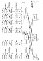
- a system for the electrostatic coating of workpieces for example motor vehicle bodies in assembly line operation, has several sources for the coating liquid, which can be formed, for example, by the above-mentioned paint ring lines, in which the coating liquid, i.e. the paint, circulates continuously.
- these sources are 10R for a red coating liquid, 10B for a blue coating liquid speed and 10G indicated for a green coating liquid.
- 10R for a red coating liquid
- 10B for a blue coating liquid speed
- 10G indicated for a green coating liquid.
- more color tones and therefore correspondingly more sources are generally provided.
- Each source 10R, 10B and 10G is connected to all three color changers 12, 14, 16, as indicated by the connecting lines.
- Each color changer 12, 14 or 15 is in turn connected to at least one atomizer which is to be fed with the corresponding color. Different types of connections are possible.
- a series connection of the color changer 12, a color pressure regulator (FDR) 18, which supplies the liquid pressure p 1 , and a throttle 26 to be explained, become one measuring cell 34 to be explained and the atomizer 40 are used.
- FDR color pressure regulator
- the atomizers 41 and 42 are supplied with blue coating liquid, for example, ie they are connected to the source 10B via a color changer 14.
- the atomizer 41 is to be operated with the pressure P2 and the atomizer 42 with the pressure P 3 with p 2 ⁇ P3 .
- This causes a branching from the color changer 14 via a first series connection from the liquid pressure regulator 20, the throttle point 28 and the measuring cell 35 to the atomizer 41 and via a second series connection from the liquid pressure regulator 22, the throttle 30 and the measuring cell 36 to the atomizer 42.
- FIG. 1 a third variant is shown in FIG. 1, namely the supply of three atomizers 43, 44 and 45 with green coating liquid and the same liquid pressure p 3 .
- the line branches from the source 10G via the liquid changer 16 into three series connections, namely via the liquid pressure regulator 23, the throttle 31 and the measuring cell 37 to the atomizer 43, via the liquid pressure regulator 24, the throttle 32 and the measuring cell 38 to the atomizer 44, and via the liquid pressure regulator 25, the throttle 33 and the measuring cell 39 to the atomizer 45.
- this additional atomizer (not shown) can be connected in parallel with atomizer 42 after measuring cell 36.
- the adjustable units namely the fluid changers, the fluid pressure regulators and the throttles are controlled by a conventional program control, the throttles and fluid changers receiving the schematically indicated electrical control signals and the color pressure regulators receiving control air signals.
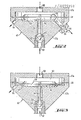
- FIGS. 2 and 3 show a section through a fluid pressure regulator according to the invention.
- a liquid pressure regulator has a housing 47 an upper part 47a and a conical lower part 47b.
- the upper part 47a and the lower part 47b are provided with an essentially circular cut in the horizontal, as seen in the drawing, and essentially rectangular in the vertical section, so that an essentially cylindrical regulator chamber 62 results.
- a deformable membrane 48 is clamped between the upper part 47a and the lower part 47b and divides the regulator chamber 62 into a control air chamber and a coating liquid chamber.
- the upper part 47a is provided with a central inlet opening 50 for the control air, which flows into the control chamber and deforms the membrane 48 in accordance with its pressure.
- the conical lower part 47b is provided with a central inlet 52 for the coating liquid, for example lacquer, which extends from the tip of the cone into the chamber for the coating liquid.
- the inlet 52 for the coating liquid is formed with a widening 53 in which the widened valve member 55 of a regulator needle 56 is located.
- the end of the regulating needle 56 opposite the valve member 55 is fastened to the membrane 48, i.e., in accordance with the deformation of the membrane 48, the valve member 55 is displaced in the cavity 53 and thus adjusts a certain flow opening and thereby in turn the flow rate.
- the upper wall of the lower part 47b opposite the membrane 48 is provided with a recess 60.
- a plate 58 is attached, which moved together with the membrane 48.
- the lower part of the plate 58 fits into the recess 60 of the lower part 47b.
- the thickness of the plate is slightly larger than the depth of the recess.
- the surface of the plate 58 opposite the depression 60 has a groove 64, which is indicated in FIGS. 2 and 3 by the dashed line. This groove leads to the outer edge of the plate in the opposite direction to the outlet 54 for the coating liquid. This groove connects the coating liquid inlet 52 to the annular channel formed between the membrane 48, the lower part 47b and the plate 58. From this annular channel, the liquid flows out of the regulator through the outlet 54.
- Fig. 2 shows the liquid pressure regulator in the control position, i.e. the diaphragm 48 and thus the regulator needle 56 are displaced in accordance with the pressure of the control air supplied in order to set a specific flow rate which depends on the distance between the valve member 55 and the wall of the inlet 52.
- a certain pressure of the coating liquid can be set in cooperation between the flow rate, the pressure of the coating liquid and the resistance section formed by the throttle (see FIG. 4).
- Fig. 3 shows the liquid pressure regulator in the fully open state, that is, at maximum pressure of the control air; in this state the valve member 55 opens the maximum flow opening, while the plate 58 rests in the recess 60 on the upper surface of the lower part 47b, that is to say a flow from the inlet 52 is only possible via the groove 64 to the annular channel.
- flushing liquid generally a solvent
- the flushing liquid thus flows from the inlet 52 past the valve member 55, through the groove 64 and the annular channel to the outlet 54.
- the plate 58 is lowered, the plate bottom and the bottom surface of the recess are flushed particularly well because of the increasing narrowing.
- the peripheral walls of the chamber are then better rinsed because of the flow in an annular channel.
- a further inlet 66 for the rinsing liquid is provided, which runs tangentially and at an angle to the horizontal plane of the chamber to the annular channel of the chamber.
- This additional inlet 66 for the rinsing liquid can be opened and closed by a needle valve 65, which is indicated schematically in FIG. 2.
- the rinsing liquid flows in a spiral flow through the annular channel, so that the entire walls of the channel are acted upon by the rinsing liquid and optimum cleaning is thereby ensured.
- FIG. 4 shows an embodiment of a throttle, which can be used with an elastic connecting line, for example a hose, between the controller and the associated atomizer.
- This throttle is formed by a schematically indicated hose clamp 70 which surrounds the elastic connecting hose 68.
- the hose clamp 70 can be adjusted electromagnetically, for example via a spindle 72, in the direction of the arrow in FIG. 4, in order to thereby compress or open the hose 68 and to narrow or expand the flow cross-section.
- the hose clamp 70 is in a specific position assigned to the corresponding flow cross section of the hose 68, which results in a precisely defined flow resistance behind the liquid pressure regulator.
- this flow resistance in connection with the control air pressure and thus the deformation of the membrane and the pressure of the coating liquid present defines the pressure with which the coating liquid is supplied to the atomizer.
- the maximum amount of flushing liquid should flow through the restrictor, i.e. the restrictor should be disabled during flushing so that the hose 68 can assume its maximum flow opening.
- the hose clamp 70 is moved upward in the direction of the arrow, so that the elastic hose 68 returns to its original shape and thus its maximum flow cross section.
- a volumetric measuring cell 34, 35, 36, 37, 38, 39 is arranged between each throttle 26, 28, 30, 31, 32, 33 and the associated atomizer 40, 41, 42, 43, 44 and 45, which works on the gear pump principle.
- This measuring cell supplies, expediently in the form of digital signals, an output signal which is proportional to the flow rate of the liquid, that is to say represents the actual value of the flow rate, as indicated by the arrows in FIG. 1.
- This actual value is compared with a predetermined target value for the flow rate and used to adjust the liquid pressure regulators 18, 20, 22, 23, 24 and 25, namely to influence the control air accordingly.
- liquid pressure regulator according to the invention can also be used in other systems if it is important that the liquid regulator is easy to clean.
Landscapes
- Spray Control Apparatus (AREA)
- Electrostatic Spraying Apparatus (AREA)
Applications Claiming Priority (2)
| Application Number | Priority Date | Filing Date | Title |
|---|---|---|---|
| DE3137074A DE3137074C2 (de) | 1981-09-17 | 1981-09-17 | Anlage zum elektrostatischen Beschichten von Werkstücken mit einer Flüssigkeit |
| DE3137074 | 1981-09-17 |
Publications (2)
| Publication Number | Publication Date |
|---|---|
| EP0075258A2 true EP0075258A2 (fr) | 1983-03-30 |
| EP0075258A3 EP0075258A3 (fr) | 1984-03-07 |
Family
ID=6142001
Family Applications (1)
| Application Number | Title | Priority Date | Filing Date |
|---|---|---|---|
| EP82108477A Withdrawn EP0075258A3 (fr) | 1981-09-17 | 1982-09-14 | Appareil pour le revêtement d'objets par un liquide |
Country Status (3)
| Country | Link |
|---|---|
| EP (1) | EP0075258A3 (fr) |
| JP (1) | JPS5888057A (fr) |
| DE (1) | DE3137074C2 (fr) |
Cited By (5)
| Publication number | Priority date | Publication date | Assignee | Title |
|---|---|---|---|---|
| EP0359383A2 (fr) * | 1988-09-16 | 1990-03-21 | Behr Industrial Equipment Inc. | Appareil de peinture électrostatique ayant un débitmètre à signal optique |
| GB2246190A (en) * | 1990-06-29 | 1992-01-22 | Honda Motor Co Ltd | Regulator for water based paint |
| EP0568910A1 (fr) * | 1992-05-04 | 1993-11-10 | ABB Fläkt Ransburg GmbH | Procédé et dispositif de nettoyage d'une installation de revêtement |
| EP1346775A1 (fr) | 2002-03-21 | 2003-09-24 | Dürr Systems GmbH | Pulvérisateur pour une installation de peinture |
| EP1287900A3 (fr) * | 2001-08-30 | 2005-12-07 | Dürr Systems GmbH | Installation de revêtement comprenant une boucle de régulation |
Citations (3)
| Publication number | Priority date | Publication date | Assignee | Title |
|---|---|---|---|---|
| FR1366004A (fr) * | 1963-04-19 | 1964-07-10 | Dosapro | Servo-moteur pneumatique notamment pour vanne à ouverture par pression |
| FR1476964A (fr) * | 1966-04-20 | 1967-04-14 | Devilbiss Co | Dispositif de commande pour pistolet pulvérisateur |
| US3605683A (en) * | 1969-04-03 | 1971-09-20 | Gyromat Corp | Paint spray system |
Family Cites Families (4)
| Publication number | Priority date | Publication date | Assignee | Title |
|---|---|---|---|---|
| US1155328A (en) * | 1915-09-28 | Nat Malleable Castings Co | Hand-brake mechanism. | |
| US3450092A (en) * | 1965-07-08 | 1969-06-17 | Vilbiss Co The De | Color change apparatus |
| DE2819302B2 (de) * | 1978-05-02 | 1980-12-18 | Ransburg Gmbh, 6056 Heusenstamm | Lackmengensteuersystem |
| US4248379A (en) * | 1979-08-16 | 1981-02-03 | Nordson Corporation | Powder spray color change system |
-
1981
- 1981-09-17 DE DE3137074A patent/DE3137074C2/de not_active Expired
-
1982
- 1982-09-14 EP EP82108477A patent/EP0075258A3/fr not_active Withdrawn
- 1982-09-17 JP JP57161128A patent/JPS5888057A/ja active Pending
Patent Citations (3)
| Publication number | Priority date | Publication date | Assignee | Title |
|---|---|---|---|---|
| FR1366004A (fr) * | 1963-04-19 | 1964-07-10 | Dosapro | Servo-moteur pneumatique notamment pour vanne à ouverture par pression |
| FR1476964A (fr) * | 1966-04-20 | 1967-04-14 | Devilbiss Co | Dispositif de commande pour pistolet pulvérisateur |
| US3605683A (en) * | 1969-04-03 | 1971-09-20 | Gyromat Corp | Paint spray system |
Cited By (7)
| Publication number | Priority date | Publication date | Assignee | Title |
|---|---|---|---|---|
| EP0359383A2 (fr) * | 1988-09-16 | 1990-03-21 | Behr Industrial Equipment Inc. | Appareil de peinture électrostatique ayant un débitmètre à signal optique |
| EP0359383A3 (fr) * | 1988-09-16 | 1990-09-26 | Behr Industrial Equipment Inc. | Appareil de peinture électrostatique ayant un débitmètre à signal optique |
| GB2246190A (en) * | 1990-06-29 | 1992-01-22 | Honda Motor Co Ltd | Regulator for water based paint |
| GB2246190B (en) * | 1990-06-29 | 1994-03-02 | Honda Motor Co Ltd | Regulator for water based paint |
| EP0568910A1 (fr) * | 1992-05-04 | 1993-11-10 | ABB Fläkt Ransburg GmbH | Procédé et dispositif de nettoyage d'une installation de revêtement |
| EP1287900A3 (fr) * | 2001-08-30 | 2005-12-07 | Dürr Systems GmbH | Installation de revêtement comprenant une boucle de régulation |
| EP1346775A1 (fr) | 2002-03-21 | 2003-09-24 | Dürr Systems GmbH | Pulvérisateur pour une installation de peinture |
Also Published As
| Publication number | Publication date |
|---|---|
| DE3137074C2 (de) | 1986-08-07 |
| JPS5888057A (ja) | 1983-05-26 |
| EP0075258A3 (fr) | 1984-03-07 |
| DE3137074A1 (de) | 1983-03-31 |
Similar Documents
| Publication | Publication Date | Title |
|---|---|---|
| DE69636182T2 (de) | Schnell lösbare Flüssigkeitskupplungseinheit | |
| DE6905187U (de) | Bewaesserungsregner | |
| DE2652584B2 (de) | Sprühvorrichtung zur Erzeugung eines pulsierenden Flüssigkeitsstrahls | |
| DE2900835A1 (de) | Steuerventil | |
| DE2923571C2 (de) | Selbstreinigendes Ventil | |
| DE2417355A1 (de) | Zentrifugaldruckduese | |
| EP1356868B1 (fr) | Buse binaire avec un insert changeables | |
| EP2983867A1 (fr) | Buse pour jet d'eau de fontaine variable | |
| EP0075258A2 (fr) | Appareil pour le revêtement d'objets par un liquide | |
| DE2733102A1 (de) | Verfahren und vorrichtung zum zerstaeuben von fluessigkeiten | |
| DE4224664A1 (de) | Rotordüse, insbesondere für ein mit Reinigungsflüssigkeit arbeitendes Hochdruckreinigungsgerät | |
| DE2757522B1 (de) | Rund- oder Ringstrahlduese zum Erzeugen und Abstrahlen eines Nebels oder Aerosols zur Beschichtung von Gegenstaenden | |
| DE3409577A1 (de) | Zentrifuge mit zentralem schlammaustrag | |
| EP0350906A2 (fr) | Séparateur à chambre toroidale | |
| DE3632269C2 (fr) | ||
| DE2261674A1 (de) | Vorrichtung zum ansaugen und beimischen von zusatzstoffen in einen fluessigkeitsstrom | |
| DE3710830C2 (fr) | ||
| EP4036329A1 (fr) | Régulateur de jet pour une armature sanitaire, ainsi qu'armature sanitaire dotée d'un tel régulateur de jet | |
| EP0177838B1 (fr) | Dispositif d'introduction de floculants dans des boues à l'intérieur de la chambre de chargement d'une centrifugeuse | |
| DE112020006287T5 (de) | Mischvorrichtung für beschichtungsflüssigkeiten und verfahren zum mischen von beschichtungsflüssigkeiten | |
| DE3243230C2 (de) | Drallkörperdüse für Spritzanlagen | |
| DE10008389A1 (de) | Verfahren und Leitungssystem zur Beeinflussung des Tropfenspektrums von fluiden Stoffen bei deren Zerstäubung | |
| DE3525889C1 (de) | Verfahren und Vorrichtung zum troepfchen- oder strahlfoermigen Austrag eines fluessigen Mediums | |
| EP3524357A1 (fr) | Dispositif separateur | |
| DE4419168A1 (de) | Druckregler für eine Sprüheinrichtung |
Legal Events
| Date | Code | Title | Description |
|---|---|---|---|
| PUAI | Public reference made under article 153(3) epc to a published international application that has entered the european phase |
Free format text: ORIGINAL CODE: 0009012 |
|
| AK | Designated contracting states |
Designated state(s): BE FR IT NL SE |
|
| EL | Fr: translation of claims filed | ||
| PUAL | Search report despatched |
Free format text: ORIGINAL CODE: 0009013 |
|
| AK | Designated contracting states |
Designated state(s): BE FR IT NL SE |
|
| 17P | Request for examination filed |
Effective date: 19840329 |
|
| STAA | Information on the status of an ep patent application or granted ep patent |
Free format text: STATUS: THE APPLICATION IS DEEMED TO BE WITHDRAWN |
|
| 18D | Application deemed to be withdrawn |
Effective date: 19850411 |
|
| RIN1 | Information on inventor provided before grant (corrected) |
Inventor name: OTT, WINFRIED Inventor name: FLEIG, GUNTHER |