EP1346775A1 - Pulvérisateur pour une installation de peinture - Google Patents
Pulvérisateur pour une installation de peinture Download PDFInfo
- Publication number
- EP1346775A1 EP1346775A1 EP03005817A EP03005817A EP1346775A1 EP 1346775 A1 EP1346775 A1 EP 1346775A1 EP 03005817 A EP03005817 A EP 03005817A EP 03005817 A EP03005817 A EP 03005817A EP 1346775 A1 EP1346775 A1 EP 1346775A1
- Authority
- EP
- European Patent Office
- Prior art keywords
- atomizer
- color
- valve
- metering valve
- atomizer according
- Prior art date
- Legal status (The legal status is an assumption and is not a legal conclusion. Google has not performed a legal analysis and makes no representation as to the accuracy of the status listed.)
- Granted
Links
Images


Classifications
-
- B—PERFORMING OPERATIONS; TRANSPORTING
- B05—SPRAYING OR ATOMISING IN GENERAL; APPLYING FLUENT MATERIALS TO SURFACES, IN GENERAL
- B05B—SPRAYING APPARATUS; ATOMISING APPARATUS; NOZZLES
- B05B1/00—Nozzles, spray heads or other outlets, with or without auxiliary devices such as valves, heating means
- B05B1/30—Nozzles, spray heads or other outlets, with or without auxiliary devices such as valves, heating means designed to control volume of flow, e.g. with adjustable passages
- B05B1/3033—Nozzles, spray heads or other outlets, with or without auxiliary devices such as valves, heating means designed to control volume of flow, e.g. with adjustable passages the control being effected by relative coaxial longitudinal movement of the controlling element and the spray head
- B05B1/304—Nozzles, spray heads or other outlets, with or without auxiliary devices such as valves, heating means designed to control volume of flow, e.g. with adjustable passages the control being effected by relative coaxial longitudinal movement of the controlling element and the spray head the controlling element being a lift valve
- B05B1/3046—Nozzles, spray heads or other outlets, with or without auxiliary devices such as valves, heating means designed to control volume of flow, e.g. with adjustable passages the control being effected by relative coaxial longitudinal movement of the controlling element and the spray head the controlling element being a lift valve the valve element, e.g. a needle, co-operating with a valve seat located downstream of the valve element and its actuating means, generally in the proximity of the outlet orifice
- B05B1/306—Nozzles, spray heads or other outlets, with or without auxiliary devices such as valves, heating means designed to control volume of flow, e.g. with adjustable passages the control being effected by relative coaxial longitudinal movement of the controlling element and the spray head the controlling element being a lift valve the valve element, e.g. a needle, co-operating with a valve seat located downstream of the valve element and its actuating means, generally in the proximity of the outlet orifice the actuating means being a fluid
-
- B—PERFORMING OPERATIONS; TRANSPORTING
- B05—SPRAYING OR ATOMISING IN GENERAL; APPLYING FLUENT MATERIALS TO SURFACES, IN GENERAL
- B05B—SPRAYING APPARATUS; ATOMISING APPARATUS; NOZZLES
- B05B1/00—Nozzles, spray heads or other outlets, with or without auxiliary devices such as valves, heating means
- B05B1/30—Nozzles, spray heads or other outlets, with or without auxiliary devices such as valves, heating means designed to control volume of flow, e.g. with adjustable passages
- B05B1/3033—Nozzles, spray heads or other outlets, with or without auxiliary devices such as valves, heating means designed to control volume of flow, e.g. with adjustable passages the control being effected by relative coaxial longitudinal movement of the controlling element and the spray head
- B05B1/304—Nozzles, spray heads or other outlets, with or without auxiliary devices such as valves, heating means designed to control volume of flow, e.g. with adjustable passages the control being effected by relative coaxial longitudinal movement of the controlling element and the spray head the controlling element being a lift valve
- B05B1/3046—Nozzles, spray heads or other outlets, with or without auxiliary devices such as valves, heating means designed to control volume of flow, e.g. with adjustable passages the control being effected by relative coaxial longitudinal movement of the controlling element and the spray head the controlling element being a lift valve the valve element, e.g. a needle, co-operating with a valve seat located downstream of the valve element and its actuating means, generally in the proximity of the outlet orifice
- B05B1/3053—Nozzles, spray heads or other outlets, with or without auxiliary devices such as valves, heating means designed to control volume of flow, e.g. with adjustable passages the control being effected by relative coaxial longitudinal movement of the controlling element and the spray head the controlling element being a lift valve the valve element, e.g. a needle, co-operating with a valve seat located downstream of the valve element and its actuating means, generally in the proximity of the outlet orifice the actuating means being a solenoid
-
- B—PERFORMING OPERATIONS; TRANSPORTING
- B05—SPRAYING OR ATOMISING IN GENERAL; APPLYING FLUENT MATERIALS TO SURFACES, IN GENERAL
- B05B—SPRAYING APPARATUS; ATOMISING APPARATUS; NOZZLES
- B05B12/00—Arrangements for controlling delivery; Arrangements for controlling the spray area
- B05B12/08—Arrangements for controlling delivery; Arrangements for controlling the spray area responsive to condition of liquid or other fluent material to be discharged, of ambient medium or of target ; responsive to condition of spray devices or of supply means, e.g. pipes, pumps or their drive means
- B05B12/085—Arrangements for controlling delivery; Arrangements for controlling the spray area responsive to condition of liquid or other fluent material to be discharged, of ambient medium or of target ; responsive to condition of spray devices or of supply means, e.g. pipes, pumps or their drive means responsive to flow or pressure of liquid or other fluent material to be discharged
-
- B—PERFORMING OPERATIONS; TRANSPORTING
- B05—SPRAYING OR ATOMISING IN GENERAL; APPLYING FLUENT MATERIALS TO SURFACES, IN GENERAL
- B05B—SPRAYING APPARATUS; ATOMISING APPARATUS; NOZZLES
- B05B12/00—Arrangements for controlling delivery; Arrangements for controlling the spray area
- B05B12/14—Arrangements for controlling delivery; Arrangements for controlling the spray area for supplying a selected one of a plurality of liquids or other fluent materials or several in selected proportions to a spray apparatus, e.g. to a single spray outlet
- B05B12/1409—Arrangements for controlling delivery; Arrangements for controlling the spray area for supplying a selected one of a plurality of liquids or other fluent materials or several in selected proportions to a spray apparatus, e.g. to a single spray outlet the selection means being part of the discharge apparatus, e.g. part of the spray gun
-
- B—PERFORMING OPERATIONS; TRANSPORTING
- B05—SPRAYING OR ATOMISING IN GENERAL; APPLYING FLUENT MATERIALS TO SURFACES, IN GENERAL
- B05B—SPRAYING APPARATUS; ATOMISING APPARATUS; NOZZLES
- B05B5/00—Electrostatic spraying apparatus; Spraying apparatus with means for charging the spray electrically; Apparatus for spraying liquids or other fluent materials by other electric means
- B05B5/025—Discharge apparatus, e.g. electrostatic spray guns
- B05B5/04—Discharge apparatus, e.g. electrostatic spray guns characterised by having rotary outlet or deflecting elements, i.e. spraying being also effected by centrifugal forces
Definitions
- the invention relates to an atomizer according to the preamble of claim 1.
- it is a rotary atomizer or air atomizers as used for the series coating of Workpieces such as vehicle bodies with frequent changing colors are generally known and common.
- Dosing pumps and piston metering devices are constructive complex, wear-prone and maintenance-intensive components and have the disadvantage of high loss of color and detergent, poor flushability, long color change times and high Pressure losses with every color change.
- Atomizers When installed in one Atomizers also undesirably increase its weight and / or size, which is particularly important for robot applications for reasons of dynamics or accessibility narrower Workpiece areas can be disadvantageous.
- piston metering devices With piston metering devices is also not a continuous funding possible, instead they require complex filling systems.
- the invention has for its object to provide an atomizer, on the one hand a very precise dosing of the coating material and on the other hand when changing materials, e.g. e.g. minimal loss of color material when changing colors, Detergent and time allowed.
- the invention avoids their Disadvantages including the relatively high loss of color change and time delays.
- the disadvantages of the known pumpless control systems not only in terms of material and time lost due to the dead spaces of the previously common color pressure regulators, but also with regard to the less precise dosage and undesirable long response times can be avoided.
- the invention is not only advantageous when changing colors, but e.g. even when changing materials in a system alternately connected to the atomizer supply lines (A / B system). If a color changing device is provided, is between this and the atomizer or its Spray head a flow measuring device.
- the dosing accuracy is already significantly improved that long control "soft" hoses between the actuator and the atomizer are eliminated.
- this can usually be particularly useful in the atomizer existing main needle valve can be used only with a suitable one to control the outflow rate Drive must be provided.
- a magnetic-inductive one proves to be a flow measuring device Measuring cell as particularly cheap, both in terms of problem-free optimization of the control loop used as well as in terms of constructive combination with the main needle valve of the atomizer.
- the color changing device should also be wholly or at least partially installed in the atomizer, whereby you the flow measuring device mentioned is connected downstream.
- Color changers suitable for this are known per se and are customary. The arrangement of the entire application technology including the color changer in the atomizer does not diminish only the loss of color changes, but also simplifies removal possible malfunctions, since only the respective atomizer be replaced, but not because of the production plant Work in the spray booth must be interrupted.
- a particularly important advantage of the invention in practice are the extremely low loss of color change of the entire system.
- the color losses are so small that under certain circumstances the usual color return from the atomizer in the paint supply system and remove the remaining small color residues similar to "short rinse" through the one forming the outlet opening of the spray head Paint nozzle can be replaced.
- the invention enables furthermore advantageously a defined "pressing" of the color to the paint tube or the nozzle of the atomizer without the pressure losses of the previously common systems in which the paint from the ring lines via slowly switching, the pressing process interrupting function valves are pressed.
- the actuator is appropriately selected, e.g. with a Proportional magnet, can also very short switching times of the atomizer can be reached, so that the on the workpiece optimize the relevant switch-on and switch-off times and the have dependent overspray losses reduced.
- the invention is suitable for atomizers as such Type that is also suitable for the changing systems known per se (e.g. DE 101 15 470), i.e. manually or automatically removed from your coating machine and counter another atomizer or against a measuring or other tools can be replaced.
- Rotary atomizer bell 1 is as usual mounted on the hollow shaft 3 driven by an air turbine 2, in which the color tube 4 with the needle 5 of the main needle valve 6 of the atomizer is arranged, which is known per se Way to open and close the opening into the paint nozzle 8 Color channel 7 is provided.
- the main needle valve 6 is used here but not only for opening and closing the color channel 7, but according to the invention as an actuator for setting the color flow rate in a closed dosing control loop.
- the winding current is from the (not shown) electronic Controller of the dosing control loop generates the actual value the color flow rate with one from the program control of the Coating system compares predetermined setpoint and at Deviation changes the current accordingly.
- the actual value is from a flow measuring device located in the atomizer 14 measured.
- Flow measuring device 14 shown schematically preferably a known as a MID system and commercially available (e.g. from from the company Endress + Hauser) available magnetic-inductive Flow measuring system, in which the conductive material through a Magnetic field flows and in this moving "conductor" according Faraday's law of induction on flow velocity or taking into account the cable cross-section voltage proportional to the flow volume is induced, the electronic measuring electrodes and a measuring amplifier Controller can be transmitted.
- the material line of the MID measuring device 14 becomes an example through the color channel 15 of the main needle valve containing the needle 5 6 formed by the generating the magnetic field Electromagnet arrangement of the measuring device 14 extends.
- the MID measuring device 14 has both constructive advantages Properties also favorable for the dosing control loop, for example regarding extremely short reaction times in particular in connection with a proportional solenoid valve.
- the MID measuring equipment is also suitable for other conductive coating materials such as fillers, powder slurry, etc.
- Fig. 1 it is assumed that for the electrostatic coating required charging of the sprayed coating material by external charging with electrodes that are on the outside of the atomizer housing 17 are arranged, in which the components described here. Suitable as a result the MID measuring cell also with regard to explosion protection requirements.
- the atomizer should preferably also contain a color changer in the example shown schematically by an arrangement of six (in practice much more) within the atomizer housing 17 in the Color channel 15 of the main needle valve 6 opening color valves 18 is indicated.
- the needle 5 extends Main needle valve 6 completely by its all colors common Color channel and through the flow measuring device 14 and by the color changer formed by the color valves 18.
- the needle 5 extends Main needle valve 6 completely by its all colors common Color channel and through the flow measuring device 14 and by the color changer formed by the color valves 18.
- the atomizer is with its flange 19 on a robot or another coating machine mounted, with a Appropriate rotary feedthrough harmful torsional stress of the lines and hoses leading into the atomizer can be avoided, in particular by those in DE 101 54 544 described central rotating union construction, at the part of the atomizer to which the line and Hose assembly is attached relative to the atomizer load-bearing end member of the machine is rotatably mounted.
- the rotary atomizer shown in Fig. 2 differentiates differs from that of FIG. 1 only in that as a drive for the main needle valve 6 e.g. centrally in the flange 19 instead of the proportional magnetic drive 19 is a pneumatic drive 29 is arranged. It essentially consists of one on the Secured shaft end 5 'of the main needle transversely to its axis Diaphragm 21 against the force of a spring 22 with compressed air or another gas to open the Main needle valve 6 is applied, the pneumatic Pressure from the electronic regulator to adjust the opening width of the main needle valve and thus the outflow rate controlled becomes.
- FIG. 3 is a further embodiment of the invention an air atomizer shown, the main needle valve 36 one at the shaft end of the main needle 35 within the atomizer e.g. on the flange 32 arranged pneumatic drive 39, the structure and mode of operation of the drive 29 in Fig. 2 can correspond.
- the color valves 38 of the color changing device and the flow measuring device 34 can 2 and Fig. 1 correspond.
- the spray head of the air atomizer shown in Fig. 3 has however, the well-known and common construction with a surrounding the paint nozzle 37 at the outlet of the main needle valve 36 Air cap 31 for the spray paint used Compressed air and a fastening nut 33.
- 3 has the main needle valve 46 but a pneumatic drive 49 with one the needle shaft 5 'attached piston 41, which acts against the force a spring 42 with controlled to regulate the outflow rate Pressure is applied (as in itself also in the already mentioned DE 101 42 355 is explained).
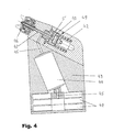
- the exemplary embodiment according to FIG. 4 shows that the Components of the atomizer described here are not necessarily in a housing body such as the cylindrical outer housing 17 must be located in Fig. 1, but also in one other part of the Atomizer can be accommodated.
- an attachment 43 with which the atomizer on his Coating machine is assembled, both the paint valves 48 of the color changing device as well as the flow measuring device Contain 44, which per se the exemplary embodiments already described can correspond. Because of the changed The design opens here, however, away from the main needle valve 46 through the color change and flow measuring devices running color channel 45 transversely into the needle bore 47 of the Main needle valve.
Landscapes
- Spray Control Apparatus (AREA)
- Nozzles (AREA)
- Electrostatic Spraying Apparatus (AREA)
- Glanulating (AREA)
- Acyclic And Carbocyclic Compounds In Medicinal Compositions (AREA)
Applications Claiming Priority (2)
| Application Number | Priority Date | Filing Date | Title |
|---|---|---|---|
| DE10212601A DE10212601A1 (de) | 2002-03-21 | 2002-03-21 | Zerstäuber für eine Beschichtungsanlage |
| DE10212601 | 2002-03-21 |
Publications (2)
| Publication Number | Publication Date |
|---|---|
| EP1346775A1 true EP1346775A1 (fr) | 2003-09-24 |
| EP1346775B1 EP1346775B1 (fr) | 2009-05-13 |
Family
ID=27771478
Family Applications (1)
| Application Number | Title | Priority Date | Filing Date |
|---|---|---|---|
| EP03005817A Expired - Lifetime EP1346775B1 (fr) | 2002-03-21 | 2003-03-14 | Pulvérisateur pour une installation de peinture |
Country Status (4)
| Country | Link |
|---|---|
| EP (1) | EP1346775B1 (fr) |
| AT (1) | ATE431195T1 (fr) |
| DE (2) | DE10212601A1 (fr) |
| ES (1) | ES2326412T3 (fr) |
Cited By (4)
| Publication number | Priority date | Publication date | Assignee | Title |
|---|---|---|---|---|
| WO2008071273A2 (fr) | 2006-12-12 | 2008-06-19 | Dürr Systems GmbH | Dispositif de revêtement équipé d'un dispositif de dosage |
| DE102006058562A1 (de) | 2006-12-12 | 2008-08-14 | Dürr Systems GmbH | Beschichtungseinrichtung mit einer Dosiervorrichtung |
| DE102007029195A1 (de) | 2007-06-25 | 2009-02-19 | Dürr Systems GmbH | Beschichtungseinrichtung mit einer Dosiervorrichtung |
| EP2036618A1 (fr) | 2006-05-09 | 2009-03-18 | DürrSystems GmbH | Système de dosage pour une installation de revêtement |
Families Citing this family (3)
| Publication number | Priority date | Publication date | Assignee | Title |
|---|---|---|---|---|
| ES2330632T3 (es) | 2003-07-28 | 2009-12-14 | Durr Systems Gmbh | Dispositivo de pulverizacion con cambiador de color para el revestimiento en serie de piezas. |
| DE102015008661A1 (de) | 2015-07-03 | 2017-01-05 | Dürr Systems Ag | Nadelventil |
| DE102015008659B4 (de) * | 2015-07-03 | 2019-06-19 | Dürr Systems Ag | Beschichtungsmittelventil und Rotationszerstäuber |
Citations (7)
| Publication number | Priority date | Publication date | Assignee | Title |
|---|---|---|---|---|
| EP0075258A2 (fr) | 1981-09-17 | 1983-03-30 | ABB Fläkt Ransburg GmbH | Appareil pour le revêtement d'objets par un liquide |
| EP0450877A2 (fr) | 1990-03-30 | 1991-10-09 | Nordson Corporation | Atomiseur rotatif avec dispositif de changement de couleur et régulateur de pression de fluide intégrés |
| US5727735A (en) * | 1993-03-04 | 1998-03-17 | Behr Systems, Inc. | Rotary atomizer for a coating arrangement |
| EP0846498A1 (fr) | 1996-12-06 | 1998-06-10 | ITW Oberflächentechnik GmbH | Installation de revêtement par pulverisation avec surveillance automatique du fonctionnement |
| EP0850693A1 (fr) * | 1996-07-18 | 1998-07-01 | ABB Industry K.K. | Dispositif de pulverisation de peinture |
| DE10115472A1 (de) * | 2001-03-29 | 2002-10-10 | Duerr Systems Gmbh | Ventileinheit für eine elektrostatische Beschichtungsanlage |
| EP1287900A2 (fr) | 2001-08-30 | 2003-03-05 | Dürr Systems GmbH | Installation de revêtement comprenant une boucle de régulation |
-
2002
- 2002-03-21 DE DE10212601A patent/DE10212601A1/de not_active Withdrawn
-
2003
- 2003-03-14 AT AT03005817T patent/ATE431195T1/de not_active IP Right Cessation
- 2003-03-14 DE DE50311511T patent/DE50311511D1/de not_active Expired - Lifetime
- 2003-03-14 ES ES03005817T patent/ES2326412T3/es not_active Expired - Lifetime
- 2003-03-14 EP EP03005817A patent/EP1346775B1/fr not_active Expired - Lifetime
Patent Citations (8)
| Publication number | Priority date | Publication date | Assignee | Title |
|---|---|---|---|---|
| EP0075258A2 (fr) | 1981-09-17 | 1983-03-30 | ABB Fläkt Ransburg GmbH | Appareil pour le revêtement d'objets par un liquide |
| EP0450877A2 (fr) | 1990-03-30 | 1991-10-09 | Nordson Corporation | Atomiseur rotatif avec dispositif de changement de couleur et régulateur de pression de fluide intégrés |
| US5727735A (en) * | 1993-03-04 | 1998-03-17 | Behr Systems, Inc. | Rotary atomizer for a coating arrangement |
| EP0850693A1 (fr) * | 1996-07-18 | 1998-07-01 | ABB Industry K.K. | Dispositif de pulverisation de peinture |
| EP0846498A1 (fr) | 1996-12-06 | 1998-06-10 | ITW Oberflächentechnik GmbH | Installation de revêtement par pulverisation avec surveillance automatique du fonctionnement |
| DE10115472A1 (de) * | 2001-03-29 | 2002-10-10 | Duerr Systems Gmbh | Ventileinheit für eine elektrostatische Beschichtungsanlage |
| EP1287900A2 (fr) | 2001-08-30 | 2003-03-05 | Dürr Systems GmbH | Installation de revêtement comprenant une boucle de régulation |
| DE10142355A1 (de) | 2001-08-30 | 2003-03-20 | Duerr Systems Gmbh | Beschichtungsanlage mit einem Regelkreis |
Cited By (6)
| Publication number | Priority date | Publication date | Assignee | Title |
|---|---|---|---|---|
| EP2036618A1 (fr) | 2006-05-09 | 2009-03-18 | DürrSystems GmbH | Système de dosage pour une installation de revêtement |
| WO2008071273A2 (fr) | 2006-12-12 | 2008-06-19 | Dürr Systems GmbH | Dispositif de revêtement équipé d'un dispositif de dosage |
| DE102006058562A1 (de) | 2006-12-12 | 2008-08-14 | Dürr Systems GmbH | Beschichtungseinrichtung mit einer Dosiervorrichtung |
| US8333164B2 (en) | 2006-12-12 | 2012-12-18 | Duerr Systems, Gmbh | Coating apparatus comprising a metering device |
| EP2853312A2 (fr) | 2006-12-12 | 2015-04-01 | Dürr Systems GmbH | Dosage ICC |
| DE102007029195A1 (de) | 2007-06-25 | 2009-02-19 | Dürr Systems GmbH | Beschichtungseinrichtung mit einer Dosiervorrichtung |
Also Published As
| Publication number | Publication date |
|---|---|
| ES2326412T3 (es) | 2009-10-09 |
| ATE431195T1 (de) | 2009-05-15 |
| EP1346775B1 (fr) | 2009-05-13 |
| DE50311511D1 (de) | 2009-06-25 |
| DE10212601A1 (de) | 2003-10-02 |
Similar Documents
| Publication | Publication Date | Title |
|---|---|---|
| EP2185293B1 (fr) | Système d'application | |
| EP2036618B1 (fr) | Système de dosage pour une installation de revêtement | |
| EP2853312B1 (fr) | Dosage ICC | |
| EP3718640A1 (fr) | Dispositif de revêtement et procédé de fonctionnement associé | |
| EP1502658B1 (fr) | Dispositif de pulvérisation avec changeur de couleur pour revêtir en série des pièces d'oeuvre | |
| EP1314483B1 (fr) | Procédé et système de distribution de doses de matériau de revêtement à un appareil de revêment | |
| DE3713999A1 (de) | Verfahren zum selbsttaetigen serienweisen beschichten von werkstuecken | |
| EP1415718B1 (fr) | Dispositif de revêtement par projection d'un liquide de revêtement | |
| EP1666158B1 (fr) | Procédé et dispositif de dosage pour l'alimentation en matériau d'un appareil de revêtement. | |
| DE102006058562A1 (de) | Beschichtungseinrichtung mit einer Dosiervorrichtung | |
| EP1245294A2 (fr) | Pulvérisateur pour une installation de revêtement et procédé d'alimentation en produit de revêtement de ce pulvérisateur | |
| EP1346775B1 (fr) | Pulvérisateur pour une installation de peinture | |
| EP0644025B1 (fr) | Procédé pour mélanger des composants et dispositif de mise en oeuvre du procédé | |
| EP1287900B1 (fr) | Installation de revêtement comprenant une boucle de régulation | |
| EP1666159B1 (fr) | Dispositif de peinture automatique muni d'un réservoir pour le matériau de revêtement | |
| DE4242715C2 (de) | Adapter mit Regelventil für automatische Material-Spritzvorrichtung | |
| WO2000010727A1 (fr) | Dispositif d'application de revetement en poudre | |
| DE3435213A1 (de) | Anordnung zur automatischen konstanthaltung der schichtdicke von markierungslinien o.dgl. | |
| EP1772194B1 (fr) | Dispositif d'alimentation pour un agent de revêtement et correspondant procédé de fonctionnement | |
| DE2855916C2 (de) | Vorrichtung zum Herstellen eines Reaktionsgemisches aus Schaumstoff oder Massivstoff bildenden, fließfähigen Komponenten | |
| EP0351579B1 (fr) | Dispositif de dosage de lubrifiant | |
| EP1348487A1 (fr) | Installation de revêtement avec un pulvérisateur et un pompe de dosage | |
| EP3711864B1 (fr) | Procédé de régulation de la pression d'alimentation dans un système de recirculation pour un dispositif de revêtement et système de recirculation | |
| DE102022131167A1 (de) | Spindeldosierpumpe und zugehöriges Betriebsverfahren | |
| WO2024110168A1 (fr) | Pompe doseuse à broche et procédé de fonctionnement associé |
Legal Events
| Date | Code | Title | Description |
|---|---|---|---|
| PUAI | Public reference made under article 153(3) epc to a published international application that has entered the european phase |
Free format text: ORIGINAL CODE: 0009012 |
|
| AK | Designated contracting states |
Kind code of ref document: A1 Designated state(s): AT BE BG CH CY CZ DE DK EE ES FI FR GB GR HU IE IT LI LU MC NL PT RO SE SI SK TR |
|
| AX | Request for extension of the european patent |
Extension state: AL LT LV MK |
|
| 17P | Request for examination filed |
Effective date: 20040128 |
|
| AKX | Designation fees paid |
Designated state(s): AT BE BG CH CY CZ DE DK EE ES FI FR GB GR HU IE IT LI LU MC NL PT RO SE SI SK TR |
|
| 17Q | First examination report despatched |
Effective date: 20040727 |
|
| GRAP | Despatch of communication of intention to grant a patent |
Free format text: ORIGINAL CODE: EPIDOSNIGR1 |
|
| GRAS | Grant fee paid |
Free format text: ORIGINAL CODE: EPIDOSNIGR3 |
|
| GRAA | (expected) grant |
Free format text: ORIGINAL CODE: 0009210 |
|
| AK | Designated contracting states |
Kind code of ref document: B1 Designated state(s): AT BE BG CH CY CZ DE DK EE ES FI FR GB GR HU IE IT LI LU MC NL PT RO SE SI SK TR |
|
| REG | Reference to a national code |
Ref country code: GB Ref legal event code: FG4D Free format text: NOT ENGLISH |
|
| REG | Reference to a national code |
Ref country code: CH Ref legal event code: EP |
|
| REG | Reference to a national code |
Ref country code: IE Ref legal event code: FG4D |
|
| REF | Corresponds to: |
Ref document number: 50311511 Country of ref document: DE Date of ref document: 20090625 Kind code of ref document: P |
|
| REG | Reference to a national code |
Ref country code: SE Ref legal event code: TRGR |
|
| REG | Reference to a national code |
Ref country code: ES Ref legal event code: FG2A Ref document number: 2326412 Country of ref document: ES Kind code of ref document: T3 |
|
| PG25 | Lapsed in a contracting state [announced via postgrant information from national office to epo] |
Ref country code: PT Free format text: LAPSE BECAUSE OF FAILURE TO SUBMIT A TRANSLATION OF THE DESCRIPTION OR TO PAY THE FEE WITHIN THE PRESCRIBED TIME-LIMIT Effective date: 20090913 Ref country code: FI Free format text: LAPSE BECAUSE OF FAILURE TO SUBMIT A TRANSLATION OF THE DESCRIPTION OR TO PAY THE FEE WITHIN THE PRESCRIBED TIME-LIMIT Effective date: 20090513 |
|
| PG25 | Lapsed in a contracting state [announced via postgrant information from national office to epo] |
Ref country code: SI Free format text: LAPSE BECAUSE OF FAILURE TO SUBMIT A TRANSLATION OF THE DESCRIPTION OR TO PAY THE FEE WITHIN THE PRESCRIBED TIME-LIMIT Effective date: 20090513 |
|
| REG | Reference to a national code |
Ref country code: IE Ref legal event code: FD4D |
|
| RAP2 | Party data changed (patent owner data changed or rights of a patent transferred) |
Owner name: DUERR SYSTEMS GMBH |
|
| PG25 | Lapsed in a contracting state [announced via postgrant information from national office to epo] |
Ref country code: RO Free format text: LAPSE BECAUSE OF FAILURE TO SUBMIT A TRANSLATION OF THE DESCRIPTION OR TO PAY THE FEE WITHIN THE PRESCRIBED TIME-LIMIT Effective date: 20090513 Ref country code: DK Free format text: LAPSE BECAUSE OF FAILURE TO SUBMIT A TRANSLATION OF THE DESCRIPTION OR TO PAY THE FEE WITHIN THE PRESCRIBED TIME-LIMIT Effective date: 20090513 Ref country code: CZ Free format text: LAPSE BECAUSE OF FAILURE TO SUBMIT A TRANSLATION OF THE DESCRIPTION OR TO PAY THE FEE WITHIN THE PRESCRIBED TIME-LIMIT Effective date: 20090513 Ref country code: EE Free format text: LAPSE BECAUSE OF FAILURE TO SUBMIT A TRANSLATION OF THE DESCRIPTION OR TO PAY THE FEE WITHIN THE PRESCRIBED TIME-LIMIT Effective date: 20090513 Ref country code: IE Free format text: LAPSE BECAUSE OF FAILURE TO SUBMIT A TRANSLATION OF THE DESCRIPTION OR TO PAY THE FEE WITHIN THE PRESCRIBED TIME-LIMIT Effective date: 20090513 |
|
| PG25 | Lapsed in a contracting state [announced via postgrant information from national office to epo] |
Ref country code: SK Free format text: LAPSE BECAUSE OF FAILURE TO SUBMIT A TRANSLATION OF THE DESCRIPTION OR TO PAY THE FEE WITHIN THE PRESCRIBED TIME-LIMIT Effective date: 20090513 |
|
| NLT2 | Nl: modifications (of names), taken from the european patent patent bulletin |
Owner name: DUERR SYSTEMS GMBH Effective date: 20100120 |
|
| PLBE | No opposition filed within time limit |
Free format text: ORIGINAL CODE: 0009261 |
|
| STAA | Information on the status of an ep patent application or granted ep patent |
Free format text: STATUS: NO OPPOSITION FILED WITHIN TIME LIMIT |
|
| PG25 | Lapsed in a contracting state [announced via postgrant information from national office to epo] |
Ref country code: BG Free format text: LAPSE BECAUSE OF FAILURE TO SUBMIT A TRANSLATION OF THE DESCRIPTION OR TO PAY THE FEE WITHIN THE PRESCRIBED TIME-LIMIT Effective date: 20090813 |
|
| 26N | No opposition filed |
Effective date: 20100216 |
|
| PG25 | Lapsed in a contracting state [announced via postgrant information from national office to epo] |
Ref country code: GR Free format text: LAPSE BECAUSE OF FAILURE TO SUBMIT A TRANSLATION OF THE DESCRIPTION OR TO PAY THE FEE WITHIN THE PRESCRIBED TIME-LIMIT Effective date: 20090814 Ref country code: MC Free format text: LAPSE BECAUSE OF NON-PAYMENT OF DUE FEES Effective date: 20100331 |
|
| REG | Reference to a national code |
Ref country code: CH Ref legal event code: PL |
|
| PG25 | Lapsed in a contracting state [announced via postgrant information from national office to epo] |
Ref country code: CH Free format text: LAPSE BECAUSE OF NON-PAYMENT OF DUE FEES Effective date: 20100331 Ref country code: LI Free format text: LAPSE BECAUSE OF NON-PAYMENT OF DUE FEES Effective date: 20100331 |
|
| PG25 | Lapsed in a contracting state [announced via postgrant information from national office to epo] |
Ref country code: AT Free format text: LAPSE BECAUSE OF NON-PAYMENT OF DUE FEES Effective date: 20100314 |
|
| PG25 | Lapsed in a contracting state [announced via postgrant information from national office to epo] |
Ref country code: CY Free format text: LAPSE BECAUSE OF FAILURE TO SUBMIT A TRANSLATION OF THE DESCRIPTION OR TO PAY THE FEE WITHIN THE PRESCRIBED TIME-LIMIT Effective date: 20090513 |
|
| PG25 | Lapsed in a contracting state [announced via postgrant information from national office to epo] |
Ref country code: HU Free format text: LAPSE BECAUSE OF FAILURE TO SUBMIT A TRANSLATION OF THE DESCRIPTION OR TO PAY THE FEE WITHIN THE PRESCRIBED TIME-LIMIT Effective date: 20091114 Ref country code: LU Free format text: LAPSE BECAUSE OF NON-PAYMENT OF DUE FEES Effective date: 20100314 |
|
| PG25 | Lapsed in a contracting state [announced via postgrant information from national office to epo] |
Ref country code: TR Free format text: LAPSE BECAUSE OF FAILURE TO SUBMIT A TRANSLATION OF THE DESCRIPTION OR TO PAY THE FEE WITHIN THE PRESCRIBED TIME-LIMIT Effective date: 20090513 |
|
| REG | Reference to a national code |
Ref country code: FR Ref legal event code: PLFP Year of fee payment: 14 |
|
| REG | Reference to a national code |
Ref country code: DE Ref legal event code: R082 Ref document number: 50311511 Country of ref document: DE Representative=s name: V. BEZOLD & PARTNER PATENTANWAELTE - PARTG MBB, DE Ref country code: DE Ref legal event code: R081 Ref document number: 50311511 Country of ref document: DE Owner name: DUERR SYSTEMS AG, DE Free format text: FORMER OWNER: DUERR SYSTEMS GMBH, 74321 BIETIGHEIM-BISSINGEN, DE |
|
| REG | Reference to a national code |
Ref country code: DE Ref legal event code: R082 Ref document number: 50311511 Country of ref document: DE Representative=s name: V. BEZOLD & PARTNER PATENTANWAELTE - PARTG MBB, DE Ref country code: DE Ref legal event code: R081 Ref document number: 50311511 Country of ref document: DE Owner name: DUERR SYSTEMS AG, DE Free format text: FORMER OWNER: DUERR SYSTEMS AG, 74321 BIETIGHEIM-BISSINGEN, DE |
|
| REG | Reference to a national code |
Ref country code: FR Ref legal event code: PLFP Year of fee payment: 15 |
|
| REG | Reference to a national code |
Ref country code: FR Ref legal event code: PLFP Year of fee payment: 16 |
|
| PGFP | Annual fee paid to national office [announced via postgrant information from national office to epo] |
Ref country code: GB Payment date: 20220321 Year of fee payment: 20 Ref country code: DE Payment date: 20220322 Year of fee payment: 20 |
|
| PGFP | Annual fee paid to national office [announced via postgrant information from national office to epo] |
Ref country code: SE Payment date: 20220321 Year of fee payment: 20 Ref country code: NL Payment date: 20220321 Year of fee payment: 20 Ref country code: IT Payment date: 20220322 Year of fee payment: 20 Ref country code: FR Payment date: 20220322 Year of fee payment: 20 Ref country code: BE Payment date: 20220321 Year of fee payment: 20 |
|
| PGFP | Annual fee paid to national office [announced via postgrant information from national office to epo] |
Ref country code: ES Payment date: 20220525 Year of fee payment: 20 |
|
| REG | Reference to a national code |
Ref country code: DE Ref legal event code: R071 Ref document number: 50311511 Country of ref document: DE |
|
| REG | Reference to a national code |
Ref country code: NL Ref legal event code: MK Effective date: 20230313 |
|
| REG | Reference to a national code |
Ref country code: BE Ref legal event code: MK Effective date: 20230314 |
|
| REG | Reference to a national code |
Ref country code: GB Ref legal event code: PE20 Expiry date: 20230313 |
|
| REG | Reference to a national code |
Ref country code: ES Ref legal event code: FD2A Effective date: 20230428 |
|
| REG | Reference to a national code |
Ref country code: SE Ref legal event code: EUG |
|
| PG25 | Lapsed in a contracting state [announced via postgrant information from national office to epo] |
Ref country code: GB Free format text: LAPSE BECAUSE OF EXPIRATION OF PROTECTION Effective date: 20230313 |
|
| P01 | Opt-out of the competence of the unified patent court (upc) registered |
Effective date: 20230512 |
|
| PG25 | Lapsed in a contracting state [announced via postgrant information from national office to epo] |
Ref country code: ES Free format text: LAPSE BECAUSE OF EXPIRATION OF PROTECTION Effective date: 20230315 |