EP0074855A2 - Affûtage automatique - Google Patents
Affûtage automatique Download PDFInfo
- Publication number
- EP0074855A2 EP0074855A2 EP82304863A EP82304863A EP0074855A2 EP 0074855 A2 EP0074855 A2 EP 0074855A2 EP 82304863 A EP82304863 A EP 82304863A EP 82304863 A EP82304863 A EP 82304863A EP 0074855 A2 EP0074855 A2 EP 0074855A2
- Authority
- EP
- European Patent Office
- Prior art keywords
- grinding
- sensing
- broach
- work head
- bed
- Prior art date
- Legal status (The legal status is an assumption and is not a legal conclusion. Google has not performed a legal analysis and makes no representation as to the accuracy of the status listed.)
- Granted
Links
Images


Classifications
-
- B—PERFORMING OPERATIONS; TRANSPORTING
- B24—GRINDING; POLISHING
- B24B—MACHINES, DEVICES, OR PROCESSES FOR GRINDING OR POLISHING; DRESSING OR CONDITIONING OF ABRADING SURFACES; FEEDING OF GRINDING, POLISHING, OR LAPPING AGENTS
- B24B49/00—Measuring or gauging equipment for controlling the feed movement of the grinding tool or work; Arrangements of indicating or measuring equipment, e.g. for indicating the start of the grinding operation
-
- B—PERFORMING OPERATIONS; TRANSPORTING
- B24—GRINDING; POLISHING
- B24B—MACHINES, DEVICES, OR PROCESSES FOR GRINDING OR POLISHING; DRESSING OR CONDITIONING OF ABRADING SURFACES; FEEDING OF GRINDING, POLISHING, OR LAPPING AGENTS
- B24B3/00—Sharpening cutting edges, e.g. of tools; Accessories therefor, e.g. for holding the tools
- B24B3/16—Sharpening cutting edges, e.g. of tools; Accessories therefor, e.g. for holding the tools of broaches
Definitions
- This invention relates to the grinding of workpieces by means of a grinding tool which operates at predetermined locations along each workpiece and the correct position of which, in relation to each location is automatically determined by a probe or sensing device operating in advance of the grinding tool.
- a workpiece to be ground is mounted on a fixed bed, the locations at which grinding is to be performed are sensed during a first or forward pass of the probe along the whole length of the workpiece, the information so obtained is stored and grinding is performed at each location in turn during a return pass of the grinding tool along the workpiece using the stored information.
- the machine is not required to be of excessive length and can be made capable of bearing greater loads than one with a movable bed or table and the grinding tool and probe are not required to be operated alternately at each location along the whole length of the workpiece with the consequent wear and tear, particularly on the cross traverse slide.
- a machine for automatically performing a series of grinding operations at predetermined locations along a workpiece comprises a fixed bed to receive the workpiece, a sensing and grinding assembly mounted on said bed and comprising a first member movable longitudinally relative to said bed, a second member mounted on said first member for vertical movement relative thereto, a third member mounted on said second member for transverse movement relative to said second member and to said bed, a work head pivotally mounted on said third member for movement relative thereto about a substantially horizontal axis, a sensing probe and a grinding tool mounted in spaced relation on said work head and a central unit for controlling the operation of the individual elements of said sensing and grinding assembly in accordance with operating instructions and sensed information fed to and stored in a micro-processor to provide an initial sensing cycle in which said sensing and grinding assembly is moved in one direction along the entire length of the workpiece with said sensing probe operative to sense and record each location on the workpiece at which grinding is to be performed, followed by a grinding cycle in which
- the machine illustrated in the drawings has a fixed bed and table, shown generally at 1, to receive and rigidly secure a broach to be sharpened.
- the bed is preferably moulded from synthetic granite for thermal stability and vibration damping and the table is preferably cast from Meehanite.
- the bed/table 1 is preferably fitted with a headstock 3 and a tailstock 2, as shown in Figs.. 1 and 2, with the head stock driven by a stepping motor 44 through a toothed belt (not shown) while for use with surface broaches, the headstock and tailstock may be replaced by magnetic chucks 51 (Figs. 5, 6 and 7) or other holding devices.
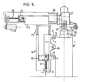
- the bed/table has a rear extension 4 (Fig. 5) provided with precision-hardened and ground guideways 5 and 6 which extend longitudinally of the bed/table and are fitted with rollers 7 to assist the movement along the guideways of a slide 8 forming part of a movable assembly 9 for sensing and grinding the teeth of a broach 50 mounted on the bed/table.
- the assembly 9 also includes a vertical slide 10 movable in guideways (not shown) in the slide 8 and a cross traverse slide 11 running in guideways in a frame lla carried by the upper end of the slide 10.
- a work head 12 is mounted at one end of the slide 11 for pivotal movement about an axis 13 (Fig. 8) extending parallel with the direction of movement of the slide 11 and provided with a sensing probe 14 and a grinding wheel 15 spaced from the probe 14 in the transverse direction of the bed/table 1.
- This construction allows of a reduction in the overall length of the machine and an increase in the load-carrying capacity and stability of the bed/table as compared with a moving bed machine.
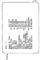
- Movement of the slides 8, 10 and 11 is effected by ball-screw and nut mechanisms 16, 17 and 18 respectively, protected by concertina-type covers 22, 23 and 24 respectively and driven, via toothed belts (not shown), by stepping motors 19, 20 and 21 respectively, under the control of a control and drive unit 40 which also controls the stepping motor 44 and operates in accordance with signals received from a micro-processor having a control panel 25 provided with a keyboard 26 through which input data is initially fed in the form of an inter-active question and answer format and displayed on a video display unit 27 as shown in Figs. 3 and 4.
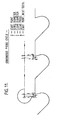
- each tooth 28 on the broach 50 To enable a constant amount to be removed from each tooth 28 on the broach 50 to be sharpened, irrespective of variations in the pitch of the teeth, the position of each tooth is sensed by the probe 14, likewise operatively connected to the control and drive unit 40, during a first or forward pass along the broach so that the positions of all the teeth are sensed and the information fed to and stored in the micro-processor prior to commencing a continuous grinding cycle on the return pass of the work head 12 along the broach.
- This procedure differs from existing methods in which each tooth is ground immediately after its position has been-sensed and the employment of a continuous sensing cycle followed by a continuous grinding cycle reduces the overall time taken to sharpen the broach and reduces wear and tear on the cross traverse slide 11.
- stock removal can be preset to suit the condition of the broach to be sharpened.
- the grinding wheel 15 is mounted on a liquid-cooled spindle 30, the speed of which can be infinitely varied over a range of from 1800 to 18000 r.p.m. by a speed-control unit 60 interposed in the driving connection between the control and drive unit 40 and the spindle 30.
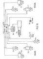
- the machine is preferably provided with an automatic diamond wheel dresser 31 (Fig. 10) for the grinding wheel 15.
- the wheel dresser 31 is mounted for rotation in the direction of the arrows E in a carriage 32 movable in the direction of the arrows V in a carriage 33 which is, in turn movable in the direction of the arrows W on a guide 34.
- Rotational movement of the dresser 31 is effected by a stepping motor 41 andlinear movement of the dresser in the directions V and W is effected by stepping motors 42 and 43 respectively.
- the stepping motors 41,y42 and 43 are operated by the control and drive unit 40 under the control of the micro-processor which is programmed through the keyboard 26 in accordance with the profile of the grinding wheel employed and to fully compensate for increments of wheel dressing.
- the speed control unit 60 for the grinding spindle 30 has access to the dresser data through the control and drive unit 40, the speed of the grinding spindle being determined by surface speed requirements after compensation for reduction in the diameter of the wheel as a result of dressing.
- the machine will perform face and gullet grinding with backing-off operations on all types of surface and form broaches using a magnetic chuck 51 or other holding device as shown in Figs. ' 5, 6 and 7 and on cylindrical broaches using a headstock 3 and compensated tailstock 2, as shown in Figs. 1 and 2. It can also be used, with the appropriate form of grinding tool, for performing other operations, e.g. cylindrical grinding and spline grinding.
- Figs. 11 and 12 illustrate typical continuous probe and grind cycles which can be employed with the machine according to the invention and Fig. 13 illustrates some examples of tooth forms which can be ground by the machine of the invention.
Priority Applications (1)
| Application Number | Priority Date | Filing Date | Title |
|---|---|---|---|
| AT82304863T ATE22027T1 (de) | 1981-09-15 | 1982-09-15 | Automatisches schleifen. |
Applications Claiming Priority (2)
| Application Number | Priority Date | Filing Date | Title |
|---|---|---|---|
| GB8127827 | 1981-09-15 | ||
| GB8127827 | 1981-09-15 |
Publications (3)
| Publication Number | Publication Date |
|---|---|
| EP0074855A2 true EP0074855A2 (fr) | 1983-03-23 |
| EP0074855A3 EP0074855A3 (en) | 1983-08-31 |
| EP0074855B1 EP0074855B1 (fr) | 1986-09-10 |
Family
ID=10524517
Family Applications (1)
| Application Number | Title | Priority Date | Filing Date |
|---|---|---|---|
| EP82304863A Expired EP0074855B1 (fr) | 1981-09-15 | 1982-09-15 | Affûtage automatique |
Country Status (8)
| Country | Link |
|---|---|
| US (1) | US4501092A (fr) |
| EP (1) | EP0074855B1 (fr) |
| JP (1) | JPS5859757A (fr) |
| AT (1) | ATE22027T1 (fr) |
| AU (1) | AU8836582A (fr) |
| DE (1) | DE3273201D1 (fr) |
| ES (1) | ES515714A0 (fr) |
| IN (1) | IN158280B (fr) |
Cited By (8)
| Publication number | Priority date | Publication date | Assignee | Title |
|---|---|---|---|---|
| EP0109687A2 (fr) * | 1982-11-22 | 1984-05-30 | WesTech Gear Corporation | Asservissement de suivi de profil de pièce pour la commande de meuleuses |
| EP0175168A2 (fr) * | 1984-09-03 | 1986-03-26 | Robert Ek | Méthode et dispositif pour meuler les bandes de patins à glace |
| WO1988003460A1 (fr) * | 1986-11-05 | 1988-05-19 | Salje Ernst | Procede et dispositif de meulage en profondeur |
| FR2625458A1 (fr) * | 1987-12-31 | 1989-07-07 | Electricite De France | Cellule de meulage |
| EP0462057A1 (fr) * | 1990-06-11 | 1991-12-18 | Robert Habib | Machine à affûter |
| EP0589826A1 (fr) * | 1992-08-27 | 1994-03-30 | L. KELLENBERGER & CO. AG | Machine de meulage |
| CN101224562B (zh) * | 2007-01-18 | 2013-07-10 | 弗立兹·斯图特公司 | 用于控制可移动工具的方法和设备和机械工具 |
| ITTO20120980A1 (it) * | 2012-11-13 | 2014-05-14 | A T P S R L | Dispositivo per la bisellatura di alberi a sezione trasversale costante, con lettura meccanica del profilo della sezione trasversale del pezzo in lavorazione |
Families Citing this family (12)
| Publication number | Priority date | Publication date | Assignee | Title |
|---|---|---|---|---|
| US4945888A (en) * | 1987-08-04 | 1990-08-07 | Korber Ag | Method of dressing grinding wheels |
| GB9510275D0 (en) * | 1995-05-22 | 1995-07-19 | Iseli & Co Ag | Saw blade tooth formation |
| US5803796A (en) * | 1996-12-18 | 1998-09-08 | Barton, Ii; Kenneth A. | Microfinishing machine |
| US6733365B1 (en) * | 1997-08-12 | 2004-05-11 | Arizona Board Of Regents | Method and apparatus for hard machining |
| DE102005013363B4 (de) | 2004-05-13 | 2023-01-05 | Weber Maschinenbau Gmbh Breidenbach | Maschine zum Schärfen von Rotationsmessern |
| DE102005020034A1 (de) * | 2005-04-29 | 2006-11-02 | Vollmer Werke Maschinenfabrik Gmbh | Vorrichtung zum Bearbeiten und Vermessen von mit Schneidzähnen versehenen Werkstücken |
| DE102005020035A1 (de) * | 2005-04-29 | 2006-11-02 | Vollmer Werke Maschinenfabrik Gmbh | Vorrichtung zum Bearbeiten von mit Schneidzähnen versehenen plattenförmigen oder zylindrischen Werkstücken |
| KR100862716B1 (ko) * | 2006-06-30 | 2008-10-10 | 박용남 | 브로치 커터의 연마 장치 |
| JP4870593B2 (ja) * | 2007-02-28 | 2012-02-08 | トヨタ自動車株式会社 | ブローチ研削装置及びブローチ研削方法 |
| JP5309860B2 (ja) * | 2008-10-08 | 2013-10-09 | 株式会社不二越 | 数値制御ブローチ研削盤の基準すくい面の位置検出方法 |
| JP5309861B2 (ja) * | 2008-10-08 | 2013-10-09 | 株式会社不二越 | 数値制御ブローチ研削盤の基準すくい面の位置検出方法 |
| DE102016217251A1 (de) * | 2016-09-09 | 2018-03-15 | Sauer Gmbh | Verfahren zum Bearbeiten eines Werkstücks aus Hartmetall für die Herstellung eines Werkzeuggrundkörpers an einer numerisch gesteuerten Werkzeugmaschine mit werkzeugtragender Arbeitsspindel |
Citations (3)
| Publication number | Priority date | Publication date | Assignee | Title |
|---|---|---|---|---|
| US3646593A (en) * | 1968-07-05 | 1972-02-29 | Forst Oswald Gmbh | Apparatus for the automatic sharpening of broaching or reaming tools |
| DE8008057U1 (de) * | 1979-10-03 | 1980-07-17 | Tacchella Macchine S.P.A., Cassine, Alessandria (Italien) | Maschine zum schaerfen von raeumnadeln |
| GB2059832A (en) * | 1979-10-03 | 1981-04-29 | Tacchella Macchine Spa | Broach sharpening machine |
Family Cites Families (6)
| Publication number | Priority date | Publication date | Assignee | Title |
|---|---|---|---|---|
| JPS4885292U (fr) * | 1972-01-18 | 1973-10-16 | ||
| US3827420A (en) * | 1972-02-28 | 1974-08-06 | Hoglund Eng And Mfg Co Inc | Grinding wheel dressing apparatus |
| US4135238A (en) * | 1976-01-26 | 1979-01-16 | Hamill Company, Inc. | Numerically controlled machine tool system |
| US4112626A (en) * | 1977-04-08 | 1978-09-12 | Daido Tokushuko Kabushiki Kaisha | Automatic deseaming apparatus for elongate block of metallic material |
| JPS54125375A (en) * | 1978-03-23 | 1979-09-28 | Fanuc Ltd | Profiling control system |
| CH631647A5 (fr) * | 1979-11-16 | 1982-08-31 | Robert Habib | Machine a affuter les outils de coupe munis de dents. |
-
1982
- 1982-09-14 AU AU88365/82A patent/AU8836582A/en not_active Abandoned
- 1982-09-14 US US06/417,840 patent/US4501092A/en not_active Expired - Fee Related
- 1982-09-15 JP JP57160754A patent/JPS5859757A/ja active Pending
- 1982-09-15 DE DE8282304863T patent/DE3273201D1/de not_active Expired
- 1982-09-15 ES ES515714A patent/ES515714A0/es active Granted
- 1982-09-15 EP EP82304863A patent/EP0074855B1/fr not_active Expired
- 1982-09-15 IN IN706/DEL/82A patent/IN158280B/en unknown
- 1982-09-15 AT AT82304863T patent/ATE22027T1/de not_active IP Right Cessation
Patent Citations (3)
| Publication number | Priority date | Publication date | Assignee | Title |
|---|---|---|---|---|
| US3646593A (en) * | 1968-07-05 | 1972-02-29 | Forst Oswald Gmbh | Apparatus for the automatic sharpening of broaching or reaming tools |
| DE8008057U1 (de) * | 1979-10-03 | 1980-07-17 | Tacchella Macchine S.P.A., Cassine, Alessandria (Italien) | Maschine zum schaerfen von raeumnadeln |
| GB2059832A (en) * | 1979-10-03 | 1981-04-29 | Tacchella Macchine Spa | Broach sharpening machine |
Non-Patent Citations (1)
| Title |
|---|
| TECHNISCHES ZENTRALBLATT F]R PRAKTISCHE METALLBEARBEITUNG, vol. 70, no. 6, June 1976, Stuttgart W.K. BEHRENDT "Erhöhte Wirtschaftlichkeit beim Schärfen von Räumwerkzeugen durch programmierbare Steuerung" pages 197-203 * |
Cited By (11)
| Publication number | Priority date | Publication date | Assignee | Title |
|---|---|---|---|---|
| EP0109687A2 (fr) * | 1982-11-22 | 1984-05-30 | WesTech Gear Corporation | Asservissement de suivi de profil de pièce pour la commande de meuleuses |
| EP0109687A3 (en) * | 1982-11-22 | 1985-10-30 | Western Gear Machinery Co. | Workpiece profile-following control system for conditioning grinders |
| EP0175168A2 (fr) * | 1984-09-03 | 1986-03-26 | Robert Ek | Méthode et dispositif pour meuler les bandes de patins à glace |
| EP0175168A3 (en) * | 1984-09-03 | 1988-08-31 | Robert Ek | Method and apparatus for grinding the slide surface of skates |
| WO1988003460A1 (fr) * | 1986-11-05 | 1988-05-19 | Salje Ernst | Procede et dispositif de meulage en profondeur |
| FR2625458A1 (fr) * | 1987-12-31 | 1989-07-07 | Electricite De France | Cellule de meulage |
| EP0462057A1 (fr) * | 1990-06-11 | 1991-12-18 | Robert Habib | Machine à affûter |
| CH683330A5 (fr) * | 1990-06-11 | 1994-02-28 | Robert Habib | Machine à affûter. |
| EP0589826A1 (fr) * | 1992-08-27 | 1994-03-30 | L. KELLENBERGER & CO. AG | Machine de meulage |
| CN101224562B (zh) * | 2007-01-18 | 2013-07-10 | 弗立兹·斯图特公司 | 用于控制可移动工具的方法和设备和机械工具 |
| ITTO20120980A1 (it) * | 2012-11-13 | 2014-05-14 | A T P S R L | Dispositivo per la bisellatura di alberi a sezione trasversale costante, con lettura meccanica del profilo della sezione trasversale del pezzo in lavorazione |
Also Published As
| Publication number | Publication date |
|---|---|
| AU8836582A (en) | 1983-03-24 |
| IN158280B (fr) | 1986-10-11 |
| JPS5859757A (ja) | 1983-04-08 |
| EP0074855B1 (fr) | 1986-09-10 |
| ATE22027T1 (de) | 1986-09-15 |
| US4501092A (en) | 1985-02-26 |
| EP0074855A3 (en) | 1983-08-31 |
| ES8404222A1 (es) | 1984-04-16 |
| DE3273201D1 (en) | 1986-10-16 |
| ES515714A0 (es) | 1984-04-16 |
Similar Documents
| Publication | Publication Date | Title |
|---|---|---|
| EP0074855B1 (fr) | Affûtage automatique | |
| US4274231A (en) | Method and apparatus for dressing a grinding wheel | |
| EP1146983B1 (fr) | Procede et machine permettant d'usiner des pieces dentees pre-usinees telles que des engrenages | |
| DE69836381T2 (de) | Werkzeugmaschine und bearbeitungsverfahren | |
| EP0712682A3 (fr) | ||
| JPS6161765A (ja) | 砥石の直交ドレツシング | |
| CN206200757U (zh) | 用于齿轮磨削加工的数控机床 | |
| US4226053A (en) | Grinding apparatus | |
| JPH0133302B2 (fr) | ||
| US4443975A (en) | Dual wheel cylindrical grinding center | |
| EP0539633B1 (fr) | Machine-outil avec portal | |
| GB2292704A (en) | Controlling the movement of dressing tools for dressing a plurality of grinding wheels by a microprocessor | |
| DE59100270D1 (de) | Spitzenlose rundschleifmaschine. | |
| CN210731930U (zh) | 一种三面同时加工的直线导轨成型机床 | |
| JP4462731B2 (ja) | 砥石の上下ドレッシング方法および研削装置 | |
| JP2623417B2 (ja) | レール溶接部自動仕上げ装置 | |
| GB2045663A (en) | Machine for finish-machining the tooth flanks of toothed workpieces | |
| US3066456A (en) | Work moving machine | |
| EP1493533B1 (fr) | Machine à meuler sans centre | |
| JPH01316112A (ja) | V字形状溝加工機 | |
| CN214721182U (zh) | 一种数控蜗杆砂轮磨齿机 | |
| DE59100441D1 (de) | Spitzenlose Rundschleifmaschine. | |
| JPH0248393B2 (fr) | ||
| US4510716A (en) | Grinding machine having improved dressing means | |
| JPS60213472A (ja) | 研削盤 |
Legal Events
| Date | Code | Title | Description |
|---|---|---|---|
| PUAI | Public reference made under article 153(3) epc to a published international application that has entered the european phase |
Free format text: ORIGINAL CODE: 0009012 |
|
| AK | Designated contracting states |
Designated state(s): AT CH DE FR GB LI SE |
|
| PUAL | Search report despatched |
Free format text: ORIGINAL CODE: 0009013 |
|
| AK | Designated contracting states |
Designated state(s): AT CH DE FR GB LI SE |
|
| 17P | Request for examination filed |
Effective date: 19840127 |
|
| GRAA | (expected) grant |
Free format text: ORIGINAL CODE: 0009210 |
|
| AK | Designated contracting states |
Kind code of ref document: B1 Designated state(s): AT CH DE FR GB LI SE |
|
| PG25 | Lapsed in a contracting state [announced via postgrant information from national office to epo] |
Ref country code: AT Effective date: 19860910 |
|
| REF | Corresponds to: |
Ref document number: 22027 Country of ref document: AT Date of ref document: 19860915 Kind code of ref document: T |
|
| REF | Corresponds to: |
Ref document number: 3273201 Country of ref document: DE Date of ref document: 19861016 |
|
| ET | Fr: translation filed | ||
| PLBI | Opposition filed |
Free format text: ORIGINAL CODE: 0009260 |
|
| PLBI | Opposition filed |
Free format text: ORIGINAL CODE: 0009260 |
|
| 26 | Opposition filed |
Opponent name: ARTHUR KLINK GMBH Effective date: 19870609 Opponent name: OSWALD FORST MASCHINENFABRIK U.APPARATEBAUANSTALT Effective date: 19870609 |
|
| 26 | Opposition filed |
Opponent name: KARL KLINK GMBH & CO. KG WERKZEUG- UND MASCHINENFA Effective date: 19870610 |
|
| PGFP | Annual fee paid to national office [announced via postgrant information from national office to epo] |
Ref country code: CH Payment date: 19890905 Year of fee payment: 8 |
|
| PGFP | Annual fee paid to national office [announced via postgrant information from national office to epo] |
Ref country code: DE Payment date: 19891108 Year of fee payment: 8 |
|
| PGFP | Annual fee paid to national office [announced via postgrant information from national office to epo] |
Ref country code: GB Payment date: 19900917 Year of fee payment: 9 |
|
| RDAG | Patent revoked |
Free format text: ORIGINAL CODE: 0009271 |
|
| STAA | Information on the status of an ep patent application or granted ep patent |
Free format text: STATUS: PATENT REVOKED |
|
| PGFP | Annual fee paid to national office [announced via postgrant information from national office to epo] |
Ref country code: SE Payment date: 19900926 Year of fee payment: 9 |
|
| PGFP | Annual fee paid to national office [announced via postgrant information from national office to epo] |
Ref country code: FR Payment date: 19900928 Year of fee payment: 9 |
|
| 27W | Patent revoked |
Effective date: 19900731 |
|
| GBPR | Gb: patent revoked under art. 102 of the ep convention designating the uk as contracting state | ||
| REG | Reference to a national code |
Ref country code: CH Ref legal event code: PL |
|
| EUG | Se: european patent has lapsed |
Ref document number: 82304863.2 Effective date: 19901107 |
|
| APAH | Appeal reference modified |
Free format text: ORIGINAL CODE: EPIDOSCREFNO |
|
| PLAB | Opposition data, opponent's data or that of the opponent's representative modified |
Free format text: ORIGINAL CODE: 0009299OPPO |