EP0072706B1 - Tonsignalverarbeitungssystem - Google Patents
Tonsignalverarbeitungssystem Download PDFInfo
- Publication number
- EP0072706B1 EP0072706B1 EP82304363A EP82304363A EP0072706B1 EP 0072706 B1 EP0072706 B1 EP 0072706B1 EP 82304363 A EP82304363 A EP 82304363A EP 82304363 A EP82304363 A EP 82304363A EP 0072706 B1 EP0072706 B1 EP 0072706B1
- Authority
- EP
- European Patent Office
- Prior art keywords
- frequency
- clock pulse
- filter
- signal
- pulse generator
- Prior art date
- Legal status (The legal status is an assumption and is not a legal conclusion. Google has not performed a legal analysis and makes no representation as to the accuracy of the status listed.)
- Expired
Links
- 230000005236 sound signal Effects 0.000 title claims description 92
- 238000006243 chemical reaction Methods 0.000 claims description 33
- 238000005070 sampling Methods 0.000 claims description 32
- 238000001914 filtration Methods 0.000 claims description 8
- 230000008878 coupling Effects 0.000 claims 2
- 238000010168 coupling process Methods 0.000 claims 2
- 238000005859 coupling reaction Methods 0.000 claims 2
- 230000006870 function Effects 0.000 description 35
- 238000010586 diagram Methods 0.000 description 16
- 238000001228 spectrum Methods 0.000 description 12
- 230000006835 compression Effects 0.000 description 10
- 238000007906 compression Methods 0.000 description 10
- 238000009826 distribution Methods 0.000 description 3
- 238000013459 approach Methods 0.000 description 2
- 230000008859 change Effects 0.000 description 2
- 230000001747 exhibiting effect Effects 0.000 description 2
- 230000010355 oscillation Effects 0.000 description 2
- 230000004044 response Effects 0.000 description 2
- 239000003990 capacitor Substances 0.000 description 1
- 230000000994 depressogenic effect Effects 0.000 description 1
- 230000006872 improvement Effects 0.000 description 1
- 230000002035 prolonged effect Effects 0.000 description 1
Images


Classifications
-
- G—PHYSICS
- G10—MUSICAL INSTRUMENTS; ACOUSTICS
- G10L—SPEECH ANALYSIS TECHNIQUES OR SPEECH SYNTHESIS; SPEECH RECOGNITION; SPEECH OR VOICE PROCESSING TECHNIQUES; SPEECH OR AUDIO CODING OR DECODING
- G10L21/00—Speech or voice signal processing techniques to produce another audible or non-audible signal, e.g. visual or tactile, in order to modify its quality or its intelligibility
- G10L21/04—Time compression or expansion
Definitions
- the present invention relates to a sound signal processing apparatus. More specifically, the present invention relates to an improvement in a sound signal processing apparatus of the kind wherein an analog sound input signal is sampled at a first clock frequency and the sampled data is stored in a memory, and wherein the data in the memory is read out under control of a second clock frequency so as to reconstitute an analog sound signal demonstrating a frequency change as compared with the original signal and maintaining the information content of the original signal.
- the reproducing speed is different from the recording speed.
- the frequency components of the sound signal as reproduced are varied as a function of the ratio VpNr of the reproducing speed Vp to the recording speed Vr. More specifically, a frequency component x(f) of the original sound signal becomes Vp ⁇ Ir.xl (Vr ⁇ Ip)f ⁇ .
- the reproducing speed Vp and the recording speed Vr specifically mean the travelling speed (cm/sec) of a magnetic tape as for a tape recorder and the speed of revolution of a record such as a disc record.
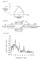
- Fig. 1 is a block diagram for explaining the principle of correcting or changing the time axis.
- Figs. 2A to 2E are graphs showing waveforms for the same purpose. Now the principle of correcting the time axis will be described.
- an original signal shown in Fig. 2A is reproduced at a low speed by means of a tape recorder, a sound signal having the time axis changed as shown in Fig. 2B is obtained.
- this sound signal is reproduced, the sound is heard with a changed pitch and therefore in order to attain the original pitch, the time axis has to be compressed as shown in Fig. 2C while the same signal is partially repeated.
- a sound signal with the time axis changed is applied to an input terminal 1 and is sampled as a function of a sampling pulse of frequency f1 obtained from a clock pulse generator, whereupon the sampled data is stored in a memory 3.
- the sampled data as stored undergoes repetitious reading of the same signal, in part, as a function of a read clock of the frequency f2 obtained from the clock pulse generator 2, whereupon the read output is obtained from an output terminal 5 through a low-pass filter 4.
- a sound signal as high speed reproduced as shown in Fig. 2D may be converted to a signal of the same frequency as the original signal by discarding appropriate portions in the waveform shown in Fig.
- the time axis of the sound signal at the input terminal 1 is corrected so that a reproduced signal having the same frequency components as the original signal is obtained at the output terminal 5.
- the speed ratio signal is supplied from the terminal 6 to the clock pulse generator 2 in order to produce the sampling pulse of the frequency f1 and the read clock pulse of the frequency f2 so as to meet the above described equation (1).
- a circuit for storing the sampled data of the sound signal may comprise a bucket brigade device (or BBD), a charge coupled device or (CCD), an analog memory such as a capacitor memory, a digital memory such as a random access memory, or the like.
- the low-pass filter 4 provided at the output of the Fig. 1 circuit serves to eliminate the high frequency signal component contained in a series of the sampled data, thereby extracting only the sound signal component.
- a desired reproducing signal frequency region is determined by the frequency f2 of the read clock and becomes lower than a half of the clock frequency f2. Therefore, in order to meet the above described equation (1), one might think of an approach in which the frequency f2 of the read clock pulse is set to a predetermined value in association with frequency region of the reproducing signal while the frequency f1 of the sampling pulse is changed in association with speed ratio signal. However, a problem arises as set forth in detail subsequently, when the frequency f1 of the sampling pulse is increased.
- Fig. 3 is a block diagram showing in outline a time axis compression and expansion circuit, similar to that described in US-A-3 934 094 abovementioned, which has been investigated by us, and Figs. 4A, 4B and 4C are graphs showing the spectrum distribution of a PCM signal in a sampled data series as developed in the circuit of Fig. 3.
- the structure and operation of the time axis compression and expansion circuit of Fig. 3 will now be described.
- a sound signal is applied through an input terminal 1 to a low-pass filter 7.
- the low-pass filter 7 serves to restrict the frequency band of the applied sound signal.
- the sound signal which passed through the low-pass filter 7 is applied to an analog/digital converter 8.
- the analog/digital converter 8 is also connected to receive sampling pulses from a clock pulse generator 21.
- the analog/digital converter 8 comprises a sample and hold circuit so that the sound signal may be sampled to be converted into a digital signal, which is then applied to a random access memory 95.
- the clock pulse generator 21 may comprise a voltage controlled oscillator the oscillation frequency of which is changeable as a function of a voltage set by a variable resistor 11, for example, and furthermore the variable resistor 11 may serve as a control voltage generator for generating a control voltage for controlling the speed of a reproducing motor 12 of a tape recorder, for example.
- the sampling pulses obtained from the clock pulse generator 21 are also applied to an address counter 91 and to a read/write switch 93.
- the address counter 91 serves to designate the write address of the random access memory 95 and provides an address signal to a multiplexer 94.
- the read/write switch 93 serves to conrol a write or read operation of the random access memory 95. To that end, the read/write switch 93 provides a read/write signal to the multiplexer 94 and random access memory 95.
- the multiplexer 94 provides an address signal from the address counter 91 to the random access memory 95 in the write mode. Accordingly, the random access memory 95 is stored with the sample data obtained by sampling the sound signal by the analog/digital converter 8.
- a clock pulse generator 22 at the read side serves to generate read clock pulses having the fixed frequency f2 and the read clock pulses are applied to a digital/analog converter 10, to an address counter 92, and to read/write switch 93.
- the address counter 92 serves to count the read clock pulses to designate the read address of the random access memory 95 and to that end the address signal is applied to the multiplexer 94.
- the read/write switch 93 provides a read control signal to the multiplexer 94 and the random access memory 95 in a read mode. Accordingly, the random access memory 95 is responsive to the read control signal and the read address signal to read the sampled data.
- the sampled data, as read is applied to the digital/analog converter 10.
- the digital/analog converter 10 serves to convert the sampled data to an analog signal as a function of the read clock pulses.
- the analog signal is applied to a low-pass filter 4 for removal of a high frequency sampling noise component and the output is obtained from the output terminal 5.
- the above described time axis compressions and expansion circuit differs from that described in US-A-3 934 094 abovementioned particularly in that a control voltage is set by means of the variable resistor 11 so that the reproducing speed by the reproducing motor 12 may be the same as the recording speed, the frequency f1 of the sampling pulse obtained from the clock pulse generator 21 may be equel to the frequency f2 of the read clock obtained from the clock pulse generator 22 as a function of the above described control voltage, and various characteristics are set so that the speed variation of the reproducing motor 12 with respect to the above described control voltage may be always equal to the variation of the frequency f1 of the sampling pulse.
- the spectrum structure of the sampled data time sequence as sampled in accordance with the write clock of the frequency f1 has approximately the same spectrum distribution as that of the input signal on both sides of frequencies equal to integral multiples of the sampling frequency f1 as shown in Fig. 4A. Accordingly, if the frequency band restriction of the input signal is incomplete, overlapping occurs between the spectrum of the input signal and the spectrum of the integral multiple of the sampling frequency (1), as shown by the dotted lines in Fig. 4A. Such overlapping gives rise to a form of distortion referred to as folded noise, and the low-pass filter 7 shown in Fig. 3 is provided for the purpose of eliminating this folded noise and must have a characteristic with sufficient attenuation at the frequency ratio f1/f2.
- the time axis compression and expansion circuit shown in Fig. 3 was such that a sound signal as low speed reproduced or high speed reproduced received as an input signl could be converted to a signal of the same frequency as that of the original signal, we found that the occasion could arise when it was desired such as in the case of an electronic musical instrument that the frequency of a musical signal was converted to a different pitch.
- the inputted musical signal could be sampled as a function of the sampling pulse and the sampled data stored, and the data then read as a function of the read clock pulse, but the frequency width of the inputted musical signal needed to be fixed while the frequency width of the outputted musical signal needed to be variable and therefore the time axis compression and expansion circuit shown in Fig. 3 could not be utilized.
- the object of the present invention is to provide a sound signal processing apparatus which is capable of changing the pitch of an inputted sound signal as desired and of providing a reconstituted sound signal of a changed pitch.
- sound signal frequency conversion apparatus comprising: a first filter for receiving and filtering an analog input signal the frequency whereof is to be converted; a first clock pulse generator for generating first clock pulses at a predetermined sampling frequency; a second clock pulse generator for generating second clock pulses at a frequency different from said sampling frequency; frequency conversion means responsive to the output of said first clock pulse generator for sampling the output of said first filter and for storing the resultant sampled data, and reponsive to the output of said second clock pulse generator for reading out said sampled data as stored whereby to obtain a frequency converted reconstitution of said analog input signal; and a second filter for receiving and filtering the thus reconstituted frequency converted signal from the frequency conversion means; as known for example from US-A-3 934 094 abovementioned, wherein in accordance with the invention the second clock pulse generator is adapted for the generation of said second clock pulses at a frequency which is variable in dependence upon a variable control signal; and the characteristics of the second filter are variable as a function of the variable frequency
- the present invention thus comprises first clock pulse generating means for generating a first clock pulse serving as a sampling pulse, second clock pulse generating means for generating a second clock pulse serving as a read clock pulse, first and second filter means provided at the input end and the output end, respectively, and frequency converting means.
- the first filter means can have a fixed attenuation characteristic and receives the inputted sound signal and provides an output to the frequency converting means.
- the frequency converting means serves to sample the sound signal as a function of the first clock pulse and store the same, and reads the stored data as a function of the second clock pulse the frequency of which is changeable in response to an external control signal.
- the read signal is applied to the second filter means the attenuation characteristic of which is changeable in association with the conversion of the frequency of the second clock pulse.
- a sound signal of changed pitch can be obtained by changing the frequency of the second clock pulse. Furthermore, since the attenuation characteristic of the second filter means is changed in association with the conversion of the frequency of the second clock pulse, the frequency band of the sound signal thus obtained can be restricted and therefore folded noise can be eliminated without increasing the frequency of the first clock pulse, i.e. the sampling pulse.
- the first clock pulse generating means and the second clock pulse generating means are switchably coupled to the input and output ends of the frequency converting means by means of a first switching means
- the first filter means and the second filter means are switchably coupled to the input and output ends of the frequency converting means by means of a second switching means.
- the sound signal obtained from the second filter means is sampled as a function of the second clock pulse and the sampled data is stored and the stored data is read as a function of the first clock pulse and is obtained from the first filter means.
- the sound signal as low speed reproduced or high speed reproduced having the same frequency as that of the original signal can be obtained. Therefore, according to the above described preferred embodiment, the pitch of the inputted sound signal can be changed or the sound signal as low speed reproduced or high speed reproduced can be changed to a sound signal of the same frequency as that of the original signal using a common circuit.
- a control signal is generated in response to the inputted sound signal and a reference sound signal. Then the frequency of the first clock pulse is changed and the attenuation characteristic of the second filter means is changed as a function of the control signal, whereby the inputted sound signal is converted to a sound signal of a pitch consistent with that of the reference sound signal.
- a musical signal of a different pitch can be converted into a musical signal of a pitch consistent with that of a reference musical signal.
- Fig. 5 is a block diagram of an outline of one embodiment of the present invention.
- Fig. 6 is a block diagram of the Fig. 5 embodiment when selecting switches 141, 142, 151 to 154 are turned to a first state.
- Fig. 7 is a graph showing a characteristic of a variable attenuation characteristic filter 13 shown in Figs. 5 and 6. First referring to Fig. 5, a structure of one embodiment of the present invention will be described.
- the Fig. 5 block diagram is substantially the same as the Fig. 3 block diagram, except for the following respects.
- the selecting switches 141 and 142 serving as a first selecting means are provided between a clock pulse generator 21 serving as a second clock pulse generating means at the input end and an address counter 91, and between a clock pulse generator 22 serving as a first clock pulse generating means at the output end and an address counter 92.
- These selecting switches 141 and 142 serve to provide the clock pulses obtained from the clock pulse generator 21 and 22 to the input and output ends of the frequency converter 9. More specifically, if and when the selecting switches 141 and 142 are turned to a second state as shown in Fig.
- the clock pulse obtained from the clock pulse generator 21 is applied to an address counter 91 as a sampling pulse and the clock pulse obtained from the clock pulse generator 22 at the output end is applied to an address counter 92 as a read clock pulse.
- the selecting switches 141 and 142 are simultaneously turned, the clock pulse obtained from the clock pulse generator 21 at the input end is applied to an address counter 92 as a read clock pulse and the clock pulse obtained from the clock pulse generator 22 at the output end is applied to an address counter 91 as a sampling pulse.
- selecting switches 151 to 154 serving as a second selecting means are provided for switching a variable attenuation characteristic filter 13 serving as a second filter means and a low-pass filter serving as a first filter means to the input or the output. More specifically, the selecting switch 151 serves to provide the sound signal applied to the input terminal 1 to the variable attenuation characteristic filter 13 or the low-pass filter 4. The selection switch 152 serves to provide the output of the variable attenuation characteristic filter 13 to the analog/digital converter 8 or the output terminal 5. The selection switch 153 serves to provide the output of the digital/analog converter 10 to the low-pass filter 4 or the variable attenuation characteristic filter 13.
- the selection switch 154 serves to provide the output of the low-pass filter 4 to the output terminal 5 or the analog/digital converter 8.
- the variable attenuation characteristic filter 13 is structured to exhibit a cutoff characteristic which is changeable as a function of a control voltage Vc obtained by manually operating a variable resistor 11. Assuming the cutoff frequency of the variable attenuation characteristic filter 13 to be fc, then the following relation is established: where k1 and k2 are constants.
- the control voltage Vc is given as a speed control voltage of the reproducing motor 12 through the switch 27. Accordingly, the speed Vp of the reproducing motor 12 is given by the following equation (4): where k3 is a constant.
- the attenuation characteristic of the low-pass filter 4 at the output end has a sufficient attenuation amount at the half of the frequency f2 of the clock pulse obtained from the clock pulse generator 22.
- the selection switches 141, 142, 151 to 154 are simultaneously turned in the above described sound signal processing apparatus, then the Fig. 5 block diagram becomes as shown in Fig. 6. More specifically, the sound signal applied to the input terminal 1 is applied to the analog/digital converter 8 through the selection switch 151, the low-pass filter 4 and the selection switch 152.
- the analog/digital converter 8 serves to sample the sound signal as a function of the clock pulse of the frequency f2 obtained from the clock pulse generator 22 and the sampled data as digital coded is stored in the address of the random access memory 95 designated by the address counter 91.
- the sampled data as stored in the random access memory 95 is read out as a function of the clock pulse of the frequency of f1 obtained from the clock pulse generator 21.
- the frequency f1 of the clock pulse is determined as a function of a control voltage determined at an adjusting position of the variable resistor 11.
- the data as read out as a function of the clock pulse is converted into an analog format by means of the digital/analog converter 10 and is obtained through the selection switch 153, the variable attenuation characteristic filter 13 and the selection switch 154 from the output terminal 5.
- the frequency conversion ratio i.e.
- the pitch conversion ratio in this case becomes the ratio f1/f2 of the frequency f1 of the sampling clock and the frequency f2 of the read clock and therefore, by properly adjusting the variable resistor 11, the pitch of the sound signal thus obtained can be arbitrarily changed.
- the cutoff frequency fc of the variable attenutaion characteristic filter 13 is changed in association with the frequency f1 of the read clock pulse as a function of the control voltage Vc as shown by the previously described equations (2) and (3). More specifically, since the variable attenuation characteristic filter 13 exhibits a sufficient attenuation amount at approximately a half of the frequency f1 of the read clock pulse as shown in Fig. 7, a portion of the read clock pulse component entering into the frequency band of the output signal can be disregarded.
- variable attenuation characteristic filter 13 is connected to the input end. Therefore, even if the sound signal as low speed reproduced or high speed reproduced from a tape recorder is inputted, the frequency band restriction is made in association with the respective frequency bands. Accordingly, the frequency of the sound signal as low speed reproduced or high speed reproduced obtained from the low-pass filter 4 of the output end is converted, whereby the original signal is obtained.
- variable attenuation characteristic filter 13, the clock pulse generator 22, the clock pulse generator 21 and the fixed attenuation characteristic low-pass filter 4 can be connected either to the input or to the output of the frequency converter 9 by means of the selection switches 141, 142, 151 to 154. Therefore, the pitch of the sound signal as inputted can be changed arbitrarily or the sound signal as low speed reproduced or high speed reproduced can be obtained with a sound signal of a reference pitch using the same circuit configuration.
- Fig. 8 is a block diagram of an outline of another embodiment of the present invention and Fig. 9 is a block diagram of the conversion ratio detecting circuit 19 shown in Fig. 8.
- the embodiment shown in Figs. 8 and 9 is adapted such that the pitch of the sound signal inputted to the input terminal 1 is tuned to the pitch of a reference sound signal inputted to the input terminal 16. More specifically, the sound signal inputted to the input terminal 1 and the reference sound signal inputted to the input terminal 16 are applied to the multiplexer 17.
- the multiplexer 17 serves to provide sound piece elements by alternately switching the respective sound signals at appropriate time intervals of say several hundreds. msec. The sound piece elements are then applied to the pitch detecting circuit 18.
- the pitch detecting circuit 18 serves to detect the respective fundamental pitch frequencies of the sound piece elements obtained from the multiplexer 17.
- the fundamental pitch frequency is meant the lowest frequency out of the frequency peaks appearing in the sound or musical signal frequency spectrum.
- the detected fundamental pitch frequency is applied to the conversion ratio detecting circuit 19.
- the conversion ratio detecting circuit 19 is responsive to the respective fundamental pitch frequencies of the two sound signals to detect the ratio T2/T1 of the respective pitch periods T1 and T2.
- the conversion ratio detecting circuit 19 comprises a comparator 191, a counter 192, resistors 193 and 194, a divider 195, and a digital/analog converter 196. More specifically, the comparator 191 serves to pulse shape the output of the pitch detector 17 shown in Fig. 8.
- the counter 192 serves to count the period T1 or T2 of the output pulse obtained from the comparator 191.
- the registers 193 and 194 serves to store the count value in the counter 192 alternately in synchronism with the selecting timing of the multiplexer 17 alternately switching the sound signal and the reference sound signal.
- the divider 195 serves to operate the ratio of the pitch periods based on the fundamental pitch periods T1 and T2 stored in the registers 193 and 194, respectively.
- the digital/analog converter 196 serves to provide the ratio of the pitch periods of the output from the divider 195 as an analog signal.
- the analog signal obtained from the above described conversion ratio detecting circuit 19 is applied to the variable gain amplifier 20 as a control signal.
- the frequency f1 of the clock pulse obtained from the clock pulse generator 22 is converted to a voltage value by means of the fN converter 24 and the ouput is applied to the variable gain amplifier 20.
- the variable gain amplifier 20 serves to control the gain of the applied voltage as a function of the ratio of the pitch periods, thereby to provide the output signal to the positive input terminal of the error amplifier 23.
- the frequency f2 of the clock pulse obtained from the clock pulse generator 21 is converted to a voltage value by means of the fN converter 25 and the output is applied to the negative input of the error amplifier 23.
- the error amplifier 23 serves to provide a control voltage based on an error of the applied two voltage values.
- the control voltage is applied to the clock pulse generator 21 and the variable attenuation characteristic filter 13.
- the sound signal applied to the input terminal 1 can be tuned to the pitch of the reference sound signal applied to the input terminal 16. More specifically, the sound signal applied to the input terminal 1 is applied through the low-pass filter 4 to the analog/digital converter 8.
- the output of the analog/digital converter 8 is sampled as a function of the clock pulse of the frequency f1 obtained from the clock pulse generator 22 and the sampled data is stored in the random access memory 95. This series of operations in the same as that of the Fig. 6 embodiment.
- the sound signal and the reference sound signal are in succession switched by means of the multiplexer 17 and the output is applied to the pitch detecting circuit 18, whereby the fundamental pitch frequencies of the respective sound signals are detected. Then the ratio m of the fundamental pitch periods T1 and T2 of the respective sound signals are operated by the conversion ratio detecting circuit 19 and the gain of the variable gain amplifier 22 is determined by the above described ratio m.
- the voltage V1 corresponding to the frequency f1 of the clock pulse obtained from the fN converter 24 is applied to the variable gain amplifier 20. Accordingly, the variable gain amplifier 20 provides the output voltage of mV1 to the error amplifier 23.
- the sampled data stored in the random access memory 95 is read as a function of the above described clock pulse.
- the sampled data is withdrawn from the output terminal 5 through the variable attenuation characteristic filter 13 the frequency band of which is restricted as a function of the voltage Vm.
- the pitch of the inputted sound signal is to be changed, it is necessary to partially disregard or repeat the sampled data stored in the random access memory 95 in reading the same. At that time, it is necessary to control the read address of the random access memory 95 in connecting the sound piece elements so that discontinuity may not arise in the output signal waveform.
- the positions of discontinuity of the read data are determined as a function of the frequency f1 of the sampling pulse, the frequency f2 of the read clock pulse and the storage capacity N of the random access memory 95 and these values can be known in advance.
- the spectrum of the sound signal including a musical signal includes a plurality of resonance frequencies as shown in an instantaneous spectrum of a piano tone in Fig. 10, for example, and therefore a complete sound signal cannot be reproduced by a conventional pitch connection by means of a single frequency converting circuit. More specifically, by making pitch connection with respect to a low frequency component, a high frequency component cannot be connected and vice versa. Therefore, it is advantageous to split the inputted sound signal into a predetermined frequency regions, to make frequency conversion of the sound signal for each of the frequency regions as split, and then to synthesize the respective sound signals.
- Fig. 11 is a block diagram of an embodiment for performing such sound signal processing.
- the sound signal applied to the input terminal 1 is applied to the bandpass filters 261 to 263.
- the bandpass filter 261 serves to extract the sound signal included in a predetermined frequency band width of the center frequency of a.
- the bandpass filter 262 serves to extract the sound signal included in a predetermined frequency band of the center frequency of 2a.
- the bandpass filter 263 serves to extract the sound signal included in a predetermined frequency band of the center frequency of 4a.
- the output of the bandpass filter 261 is applied to the analog/ digital converter 81, the output of the bandpass filter 262 is applied to the analog/digital converter 82, and the output of the bandpass filter 263 is applied to the analog/digital converter 83.
- the clock pulse of the frequency 4f1 obtained from the clock generator 21 is applied to the analog/digital converter 83 and the frequency converter 903.
- the clock pulse is applied to the counter 27, whereby the frequency is divided by two and four.
- the clock pulse of the frequency 2f1 as frequency divided by two is applied to the analog/digital converter 82 and the frequency converter 902.
- the clock pulse of the frequency f1 as frequency divided by four is applied to the analog/digital converter 81 and the frequency converter 901.
- the frequency converters 901 to 903 are structured in substantially the same manner as that of the frequency converter 9. Accordingly, the sound signal of the frequency band with the center frequency a is sampled as a function of the clock pulse of the frequency f1 and the sampled data is stored in the frequency converter 901. The sound signal of the frequency band with the center frequency 2a is sampled by the analog/ digital converter 82 as a function of the clock pulse of the frequency 2f1 and the sampled data is stored in the frequency converter 902. Furthermore, the sound signal of the frequency band with the center frequency of 4a is sampled by the analog/digital converter 83 as a function of the clock pulse of the frequency 4f1.
- the clock pulse of the frequency 4f2 obtained from the clock generator 22 at the output end is applied to the above described frequency converter 903 and the digital/analog converter 103.
- the above described clock pulse is also applied to the counter 28 so that the same is frequency divided by two and four.
- the clock pulse of the frequency 2f2 as frequency divided by two is applied to the frequency converter 902 and the digital/analog converter 102.
- the clock pulse of the frequency f2 as frequency divided by four is applied to the frequency converter 901 and the digital/analog converter 101. Accordingly, the sampled data stored in the frequency converter 901 is read as a function of the clock pulse of the frequency f2 and is converted into an analog signal by means of the digital/analog converter 101.
- the sampled data stored in the frequency converter 902 is read as a function of the clock pulse of the frequency 2f2 and is converted into the analog signal by means of the digital/analog converter 102. Furthermore, the sampled data stored in the frequency converter 903 is read as a function of the clock pulse of the frequency 4f2 and is converted into the analog signal by means of the digital/analog converter 103. Furthermore, the voltage as set by the variable resistor 11 for controlling the oscillation frequency of the clock pulse generator 22 is applied to the variable attenuation characteristic filter 131. The voltage is voltage divided by the resistors 281 and 282 and the divided voltage is applied to the variable attenuation characteristic filter 132 as a voltage corresponding to the frequency 2f2 of the read clock.
- the voltage set by the variable resistor 11 is voltage divided by the resistors 291 and 292 and the divided voltage is applied to the variable attenuation characteristic filter 133 as a voltage corresponding to the frequency 4f2 of the clock pulse. Accordingly, the variable attenuation characteristic filter 131 comes to exhibit an attenuation characteristic corresponding to the voltage set by the variable resistor 11 and the analog signal obtained from the digital/analog converter 101 is applied to the adding circuit 29. Similarly, the variable attenuation characteristic filter 132 comes to exhibit an attenuation characteristic corresponding to the clock pulse of the frequency 2f2 and the analog signal obtained from the digital/analog converter 102 is applied to the adding circuit 29.
- variable attenuation characteristic filter 133 comes to exhibit an attenuation characteristic corresponding to the clock pulse of the frequency 4f2 and the analog signal obtained from the digital/analog converter 103 is applied to the adding circuit 29.
- the adding circuit 29 sums up the sound signals as frequency converted for the respective frequency regions, thereby to provide a summed up output at the output terminal 5.
- the sound signals are sampled and stored for the respective frequency regions as split and the sampled data as stored is read for the respective frequency regions as a functionn of the corresponding read clock pulses, whereupon the outputs are applied to the filters exhibiting the attenuation characteristic associated with the read clock pulses and the outputs are synthesized. Therefore, the waveform connection processing of the sound piece elements can be done for each of the frequency regions as split by means of each of the frequency converters 901 to 903. Accordingly, pitch connection processing can also be done for each of the respective frequency spectrums.
Landscapes
- Engineering & Computer Science (AREA)
- Computational Linguistics (AREA)
- Quality & Reliability (AREA)
- Signal Processing (AREA)
- Health & Medical Sciences (AREA)
- Audiology, Speech & Language Pathology (AREA)
- Human Computer Interaction (AREA)
- Physics & Mathematics (AREA)
- Acoustics & Sound (AREA)
- Multimedia (AREA)
- Electrophonic Musical Instruments (AREA)
Claims (7)
dadurch gekennzeichnet, daß der zweite Taktgeber (21) angepaßt ist zur Erzeugung der zweitem Taktpulse mit einer Frequenz, die variabel ist in Abhängigkeit von einem variablen Steuersignal (11); und
Applications Claiming Priority (8)
| Application Number | Priority Date | Filing Date | Title |
|---|---|---|---|
| JP56129824A JPS5831397A (ja) | 1981-08-19 | 1981-08-19 | 音声信号処理装置 |
| JP129824/81 | 1981-08-19 | ||
| JP130980/81 | 1981-08-20 | ||
| JP56130980A JPS5831399A (ja) | 1981-08-20 | 1981-08-20 | 音響信号の周波数変換装置 |
| JP56148472A JPS5849999A (ja) | 1981-09-18 | 1981-09-18 | 音響信号の周波数同調装置 |
| JP148472/81 | 1981-09-18 | ||
| JP56205955A JPS58106598A (ja) | 1981-12-18 | 1981-12-18 | 信号周波数変換装置 |
| JP205955/81 | 1981-12-18 |
Publications (2)
| Publication Number | Publication Date |
|---|---|
| EP0072706A1 EP0072706A1 (de) | 1983-02-23 |
| EP0072706B1 true EP0072706B1 (de) | 1986-11-12 |
Family
ID=27471489
Family Applications (1)
| Application Number | Title | Priority Date | Filing Date |
|---|---|---|---|
| EP82304363A Expired EP0072706B1 (de) | 1981-08-19 | 1982-08-18 | Tonsignalverarbeitungssystem |
Country Status (3)
| Country | Link |
|---|---|
| US (1) | US4586191A (de) |
| EP (1) | EP0072706B1 (de) |
| DE (1) | DE3274312D1 (de) |
Families Citing this family (11)
| Publication number | Priority date | Publication date | Assignee | Title |
|---|---|---|---|---|
| EP0275099B1 (de) * | 1987-01-16 | 1994-03-23 | Sharp Kabushiki Kaisha | Gerät zur Sprachanalyse und -synthese |
| US4989249A (en) * | 1987-05-29 | 1991-01-29 | Sanyo Electric Co., Ltd. | Method of feature determination and extraction and recognition of voice and apparatus therefore |
| JP2853147B2 (ja) * | 1989-03-27 | 1999-02-03 | 松下電器産業株式会社 | 音程変換装置 |
| JP3435168B2 (ja) * | 1991-11-18 | 2003-08-11 | パイオニア株式会社 | 音程制御装置及び方法 |
| US5920842A (en) * | 1994-10-12 | 1999-07-06 | Pixel Instruments | Signal synchronization |
| US5758257A (en) * | 1994-11-29 | 1998-05-26 | Herz; Frederick | System and method for scheduling broadcast of and access to video programs and other data using customer profiles |
| JPH08195028A (ja) * | 1995-01-13 | 1996-07-30 | Victor Co Of Japan Ltd | 音声処理回路 |
| JP3073942B2 (ja) * | 1997-09-12 | 2000-08-07 | 日本放送協会 | 音声処理方法、音声処理装置および記録再生装置 |
| US6009386A (en) * | 1997-11-28 | 1999-12-28 | Nortel Networks Corporation | Speech playback speed change using wavelet coding, preferably sub-band coding |
| JP2000122700A (ja) * | 1998-10-21 | 2000-04-28 | Kawai Musical Instr Mfg Co Ltd | ピッチシフト装置及びその方法 |
| JP3450237B2 (ja) * | 1999-10-06 | 2003-09-22 | 株式会社アルカディア | 音声合成装置および方法 |
Family Cites Families (12)
| Publication number | Priority date | Publication date | Assignee | Title |
|---|---|---|---|---|
| US3394228A (en) * | 1965-06-03 | 1968-07-23 | Bell Telephone Labor Inc | Apparatus for spectral scaling of speech |
| GB1261385A (en) * | 1968-07-24 | 1972-01-26 | Matsushita Electric Industrial Co Ltd | Speech analyzing apparatus |
| US3631365A (en) * | 1968-11-01 | 1971-12-28 | Dolby Laboratories Inc | Signal compressors and expanders |
| US3816664A (en) * | 1971-09-28 | 1974-06-11 | R Koch | Signal compression and expansion apparatus with means for preserving or varying pitch |
| JPS5727627B2 (de) * | 1972-08-28 | 1982-06-11 | ||
| US3860760A (en) * | 1973-06-06 | 1975-01-14 | Us Army | Electronic time compressor or expander |
| US3988546A (en) * | 1974-09-13 | 1976-10-26 | General Signal Corporation | System for audibly recognizing an aurally unclassifiable signal |
| US3965298A (en) * | 1975-05-05 | 1976-06-22 | Long Enterprises | Deep sea diving speech converter |
| JPS52134303A (en) * | 1976-05-06 | 1977-11-10 | Tadamutsu Hirata | Device for processing audio pitch correcting signal |
| US4271331A (en) * | 1979-06-27 | 1981-06-02 | In-Mar Electronics | Analog processing system for real-time conversion of the frequency of analog signals |
| JPS56119909A (en) * | 1980-02-22 | 1981-09-19 | Victor Co Of Japan Ltd | Reproducing device for speed variable digital signal |
| US4462555A (en) * | 1982-12-13 | 1984-07-31 | At&T Technologies, Inc. | Split reel with quick-release flange |
-
1982
- 1982-08-09 US US06/406,442 patent/US4586191A/en not_active Expired - Fee Related
- 1982-08-18 DE DE8282304363T patent/DE3274312D1/de not_active Expired
- 1982-08-18 EP EP82304363A patent/EP0072706B1/de not_active Expired
Also Published As
| Publication number | Publication date |
|---|---|
| US4586191A (en) | 1986-04-29 |
| DE3274312D1 (en) | 1987-01-02 |
| EP0072706A1 (de) | 1983-02-23 |
Similar Documents
| Publication | Publication Date | Title |
|---|---|---|
| US4433604A (en) | Frequency domain digital encoding technique for musical signals | |
| US4715257A (en) | Waveform generating device for electronic musical instruments | |
| US4568912A (en) | Method and system for translating digital signal sampled at variable frequency | |
| US4829463A (en) | Programmed time-changing coefficient digital filter | |
| US4626827A (en) | Method and system for data compression by variable frequency sampling | |
| EP0072706B1 (de) | Tonsignalverarbeitungssystem | |
| US3949175A (en) | Audio signal time-duration converter | |
| EP0337458A2 (de) | Vorrichtung zur Synthese von analogen Signalen in PCM | |
| US6300553B2 (en) | Pitch shifter | |
| US3936610A (en) | Dual delay line storage sound signal processor | |
| US4402243A (en) | Synthesizer circuit for electronic musical instrument | |
| US4245541A (en) | Apparatus for reducing noise in digital to analog conversion | |
| US4638710A (en) | Periodic waveform generation by nonrecyclically reading lower frequency audio samples and recyclically reading higher frequency audio samples | |
| JPH10126645A (ja) | 周波数変換装置 | |
| JPH057903B2 (de) | ||
| JP3134602B2 (ja) | 波形記録装置 | |
| JPH023999B2 (de) | ||
| SU1141591A1 (ru) | Телевизионный цветомузыкальный синтезатор | |
| JPS5855393Y2 (ja) | 集団演奏教習装置 | |
| US4683795A (en) | Periodic wave form generation by recyclically reading amplitude and frequency equalized digital signals | |
| JPH0690637B2 (ja) | 補間方法 | |
| SU1647918A1 (ru) | Устройство преобразовани частоты в код | |
| SU1453622A1 (ru) | Устройство дл усилени звука | |
| SU1053018A1 (ru) | Устройство дл измерени амплитудно-частотных характеристик | |
| JPH0535510B2 (de) |
Legal Events
| Date | Code | Title | Description |
|---|---|---|---|
| PUAI | Public reference made under article 153(3) epc to a published international application that has entered the european phase |
Free format text: ORIGINAL CODE: 0009012 |
|
| AK | Designated contracting states |
Designated state(s): DE FR GB IT |
|
| 17P | Request for examination filed |
Effective date: 19830816 |
|
| GRAA | (expected) grant |
Free format text: ORIGINAL CODE: 0009210 |
|
| AK | Designated contracting states |
Kind code of ref document: B1 Designated state(s): DE FR GB IT |
|
| REF | Corresponds to: |
Ref document number: 3274312 Country of ref document: DE Date of ref document: 19870102 |
|
| ITF | It: translation for a ep patent filed | ||
| ET | Fr: translation filed | ||
| PLBE | No opposition filed within time limit |
Free format text: ORIGINAL CODE: 0009261 |
|
| STAA | Information on the status of an ep patent application or granted ep patent |
Free format text: STATUS: NO OPPOSITION FILED WITHIN TIME LIMIT |
|
| 26N | No opposition filed | ||
| ITTA | It: last paid annual fee | ||
| PGFP | Annual fee paid to national office [announced via postgrant information from national office to epo] |
Ref country code: GB Payment date: 19950807 Year of fee payment: 14 |
|
| PGFP | Annual fee paid to national office [announced via postgrant information from national office to epo] |
Ref country code: FR Payment date: 19950809 Year of fee payment: 14 |
|
| PGFP | Annual fee paid to national office [announced via postgrant information from national office to epo] |
Ref country code: DE Payment date: 19950828 Year of fee payment: 14 |
|
| PG25 | Lapsed in a contracting state [announced via postgrant information from national office to epo] |
Ref country code: GB Effective date: 19960818 |
|
| GBPC | Gb: european patent ceased through non-payment of renewal fee |
Effective date: 19960818 |
|
| PG25 | Lapsed in a contracting state [announced via postgrant information from national office to epo] |
Ref country code: FR Effective date: 19970430 |
|
| PG25 | Lapsed in a contracting state [announced via postgrant information from national office to epo] |
Ref country code: DE Effective date: 19970501 |
|
| REG | Reference to a national code |
Ref country code: FR Ref legal event code: ST |