EP0072652B1 - Variable stereomicroscope - Google Patents
Variable stereomicroscope Download PDFInfo
- Publication number
- EP0072652B1 EP0072652B1 EP82304146A EP82304146A EP0072652B1 EP 0072652 B1 EP0072652 B1 EP 0072652B1 EP 82304146 A EP82304146 A EP 82304146A EP 82304146 A EP82304146 A EP 82304146A EP 0072652 B1 EP0072652 B1 EP 0072652B1
- Authority
- EP
- European Patent Office
- Prior art keywords
- objective lens
- secondary objective
- axis
- optical system
- light
- Prior art date
- Legal status (The legal status is an assumption and is not a legal conclusion. Google has not performed a legal analysis and makes no representation as to the accuracy of the status listed.)
- Expired
Links
Images

Classifications
-
- G—PHYSICS
- G02—OPTICS
- G02B—OPTICAL ELEMENTS, SYSTEMS OR APPARATUS
- G02B27/00—Optical systems or apparatus not provided for by any of the groups G02B1/00 - G02B26/00, G02B30/00
- G02B27/10—Beam splitting or combining systems
- G02B27/14—Beam splitting or combining systems operating by reflection only
- G02B27/144—Beam splitting or combining systems operating by reflection only using partially transparent surfaces without spectral selectivity
-
- G—PHYSICS
- G02—OPTICS
- G02B—OPTICAL ELEMENTS, SYSTEMS OR APPARATUS
- G02B21/00—Microscopes
- G02B21/18—Arrangements with more than one light path, e.g. for comparing two specimens
- G02B21/20—Binocular arrangements
- G02B21/22—Stereoscopic arrangements
Definitions
- This invention relates to a microscope which has a high aperture and magnification, and a continuously variable degree of stereoscopy.
- the advantages of high magnification and aperture are retained, but the improved optical system is such that the angle of stereoscopy can be varied and if required reverse stereoscopy can be achieved.
- an optical system comprising a first objective lens system, first and second secondary objective lens systems arranged to provide focussed images from light received from the front objective lens system; and between the front objective lens and the secondary objective lens systems a beam directing means comprising a semi-reflecting beam dividing surface and arranged to receive light from the front objective lens and to direct a part of said light to each of said secondary objective lens systems, characterized in that the beam directing means comprises a reflecting surface and is movable along the axis of the front objective lens with respect to that lens and to the secondary objective lens systems, said movement causing a variation in the angle of stereoscopy of the system.
- the beam directing means comprises a beam dividing surface arranged to reflect part of the light received from the objective lens system to the first secondary objective lens system, and to transmit the remainder of said light to a reflecting surface which reflects light to the second secondary objective lens system.
- a prism block movable along the axis may be provided.
- a binocular but non-stereoscopic microscope In one "neutral" position of the beam dividing means and the reflecting surface, a binocular but non-stereoscopic microscope will be provided. If, however, the beam dividing means and reflecting surface are moved closer to the front objective lens than the "neutral" position a stereomicroscope is provided, and if they are moved further away than the "neutral” position, reverse stereoscopy is achieved. This is so for a microscope in which a final erect image is formed. If the microscope forms an inverted image, raising the beam dividing means will produce stereoscopy, whilst lowering them will produce reverse stereoscopy.
- the microscope of the invention can therefore be regarded as similar to a conventional binocular microscope but modified to allow movement of the beam divider and reflector. This is the reverse of the normal aim which would be to fix the beam divider and reflector at a precisely defined position.
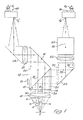
- the microscope has a front objective lens system 10 arranged above an object 0.
- the lens system 10 is here depicted schematically as a single elemental component.
- this system would, of course, be of more complex construction.
- a prism block 12 Spaced above the lens system 10 is a prism block 12 having a receiving face 14 perpendicular to the optical axis A of lens system 10, an internal beam-dividing surface 16 at an angle of 45° to the optical axis and a fully reflecting surface 18 above and perpendicular to the surface 16.
- first secondary objective lens system consisting of a reflecting prism 20, a first secondary objective lens 22 and a glass block 24.
- second secondary objective lens system consisting of a second secondary objective lens 26 and a reflecting prism 28. Spaced from the block 24 and the prism 28 are respectively a right and left Porro prism system 38, 40 viewed by right and left eyes E R , E L .
- the prism block 12, and therefore the beam-dividing surface 16 and the reflecting surface 18, is movable along the optical axis of the front objective lens 10 as indicated by the arrow 13.
- a rack-and-pinion mechanism (not illustrated) or any other suitable mechanical arrangement can be used.
- Light from the object O is collimated by the front objective lens system 10 and passes through the receiving face 14 to the beam-dividing surface 16.
- Light reflected through 90° by the surface 16 passes to the prism 20 which reflects it through the first secondary objective lens 22 to form an image O R ' for the right eye.
- Light transmitted by the surface 16 is reflected through 90° by the surface 18 to pass through the second secondary objective lens 26 and is reflected by the reflecting prism 28 to form an image O L ' for the left eye.
- the glass block 24 equalises the path lengths in glass.
- the images OR" 0,', which are inverted, are viewed through the conventional Porro prism systems 38, 40 to give an erect final image.
- each secondary objective lens 22, 26 receives light from a different part of the surface of the objective lens, the two parts overlapping on the central part of the lens.
- Light forming the image O R ' at the right eye is shown by the two extreme rays 30, (shown as dashes) and a central ray 32.
- Light forming the image O L ' at the left eye is shown by the two extreme rays 34 (shown chain-dotted) and a central ray 36.
- the angle between each extreme ray 30 and the associated central ray 32, and between each extreme ray 34 and the associated central ray 36 is the aperture angle of the microscope.
- the two central rays 32, 36 lie on opposite sides of the axis of the lens 10 and the angle 0 between them is the angle of stereoscopy of the microscope.
- FIG 2 the effect of moving the prism block 12 away from the objective lens is illustrated.
- the block is in a "neutral" position; a binocular, non-stereoscopic microscope is provided, i.e. the central rays 32, 36 to each secondary objective lens system coincide in their passage through the front objective lens 10; the extreme rays 30, 34 also coincide but are not shown in Figure 2; and the aperture angle is maintained.
- the positions of the surfaces 16, 18 in the Figure 1 arrangement are shown by the broken lines.
Description
- This invention relates to a microscope which has a high aperture and magnification, and a continuously variable degree of stereoscopy.
- In the specification of UK Patent No. 1,139,385, Bausch and Lomb, a stereomicroscope is described which has a high magnification and a long working distance; this is achieved by providing a pair of apertures offset with respectto the central rays from the axial point of an object to the two eyepiece lens systems. But as disclosed in the stereoscopic angle is fixed; while a variable angle could be provided, it would require a mechanically complex linkage system and would result, when operated, in the disadvantage that one eyepiece would be at a different height from the other.
- In the present invention, the advantages of high magnification and aperture are retained, but the improved optical system is such that the angle of stereoscopy can be varied and if required reverse stereoscopy can be achieved.
- According to the invention, an optical system comprising a first objective lens system, first and second secondary objective lens systems arranged to provide focussed images from light received from the front objective lens system; and between the front objective lens and the secondary objective lens systems a beam directing means comprising a semi-reflecting beam dividing surface and arranged to receive light from the front objective lens and to direct a part of said light to each of said secondary objective lens systems, characterized in that the beam directing means comprises a reflecting surface and is movable along the axis of the front objective lens with respect to that lens and to the secondary objective lens systems, said movement causing a variation in the angle of stereoscopy of the system.
- The beam directing means comprises a beam dividing surface arranged to reflect part of the light received from the objective lens system to the first secondary objective lens system, and to transmit the remainder of said light to a reflecting surface which reflects light to the second secondary objective lens system. For example, a prism block movable along the axis may be provided.
- In one "neutral" position of the beam dividing means and the reflecting surface, a binocular but non-stereoscopic microscope will be provided. If, however, the beam dividing means and reflecting surface are moved closer to the front objective lens than the "neutral" position a stereomicroscope is provided, and if they are moved further away than the "neutral" position, reverse stereoscopy is achieved. This is so for a microscope in which a final erect image is formed. If the microscope forms an inverted image, raising the beam dividing means will produce stereoscopy, whilst lowering them will produce reverse stereoscopy. The microscope of the invention can therefore be regarded as similar to a conventional binocular microscope but modified to allow movement of the beam divider and reflector. This is the reverse of the normal aim which would be to fix the beam divider and reflector at a precisely defined position.
- The invention will now be described by way of example only with reference to the accompanying drawings in which:-
- Figure 1 illustrates schematically the optical arrangement of a variable stereoscopic microscope according to the invention in a position giving a stereoscopic image of an object for the case when an erect final image is formed;
- Figure 2 illustrates the microscope at a "neutral" position at which there is no stereoscopic effect; and
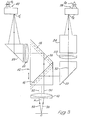
- Figure 3 illustrates a microscope having reverse stereoscopy for the case when an erect final image is formed.
- Referring now to Figure 1, the microscope has a front
objective lens system 10 arranged above an object 0. In the interests of simplicity, thelens system 10 is here depicted schematically as a single elemental component. For achieving higher numerical apertures, this system would, of course, be of more complex construction. Spaced above thelens system 10 is aprism block 12 having a receivingface 14 perpendicular to the optical axis A oflens system 10, an internal beam-dividingsurface 16 at an angle of 45° to the optical axis and a fully reflectingsurface 18 above and perpendicular to thesurface 16. - On one side of the
prism block 12 is a first secondary objective lens system consisting of a reflectingprism 20, a first secondaryobjective lens 22 and aglass block 24. On the other side of theprism block 12 is a second secondary objective lens system consisting of a second secondaryobjective lens 26 and a reflectingprism 28. Spaced from theblock 24 and theprism 28 are respectively a right and left Porroprism system - The
prism block 12, and therefore the beam-dividingsurface 16 and the reflectingsurface 18, is movable along the optical axis of the frontobjective lens 10 as indicated by thearrow 13. A rack-and-pinion mechanism (not illustrated) or any other suitable mechanical arrangement can be used. - Light from the object O is collimated by the front
objective lens system 10 and passes through thereceiving face 14 to the beam-dividingsurface 16. Light reflected through 90° by thesurface 16 passes to theprism 20 which reflects it through the first secondaryobjective lens 22 to form an image OR' for the right eye. Light transmitted by thesurface 16 is reflected through 90° by thesurface 18 to pass through the second secondaryobjective lens 26 and is reflected by the reflectingprism 28 to form an image OL' for the left eye. Theglass block 24 equalises the path lengths in glass. The images OR" 0,', which are inverted, are viewed through the conventional Porroprism systems - In Figure 1, the position of the
prism block 12 with respect to the secondary objective system is such that each secondaryobjective lens extreme rays 30, (shown as dashes) and acentral ray 32. Light forming the image OL' at the left eye is shown by the two extreme rays 34 (shown chain-dotted) and acentral ray 36. At the object, the angle between eachextreme ray 30 and the associatedcentral ray 32, and between eachextreme ray 34 and the associatedcentral ray 36, is the aperture angle of the microscope. The twocentral rays lens 10 and the angle 0 between them is the angle of stereoscopy of the microscope. - In Figure 2, the effect of moving the
prism block 12 away from the objective lens is illustrated. The block is in a "neutral" position; a binocular, non-stereoscopic microscope is provided, i.e. thecentral rays objective lens 10; theextreme rays surfaces - From Figures 1 and 2 the effect of moving the
prism block 12 along the axis of the frontobjective lens 10 can be seen. Movement from the "neutral" position of Figure 2 towards the lens, to the Figure 1 position, generates a stereoscopic effect, the angle of stereoscopy 8 being proportional to the linear movement ofprism block 12 from the "neutral" position. Thus by a simple mechanical movement, the angle of stereoscopy θ can be varied while maintaining a wide aperture angle a and, if desired, a large working distance. The advantage is achieved in this stereomicroscope using a conventional objective lens. It will be seen that 8<a; in contrast, in prior art stereomicroscopes such as the Greenough microscope, θ>o, so that having large to achieve high lateral resolution carries with it a higher angle of stereoscopy with consequent distortion of perceived space; the microscope of the invention does not have this disadvantage. Further, the microscope is not resolution-blocked by elimination of half of the rays reaching each eyepiece, which is an arrangement used in yet another stereomicroscope. - Referring again to Figure 1, if the focal length of the
lens 10 is F and the separation of the parallelcentral rays central ray lens 10 is d/2, then:-
- Referring now to Figure 2, in which the position of
central ray 32 corresponding to the Figure 1 arrangement is shown by a dotted line, by simple geometry the offset of thesurface 16 is seen to be d/2. - Rearranging equation (1):-

prism block 12 would be ±7 millimetres from the "neutral", Figure 2, position. Typical corresponding apertures will be a numerical aperture sin a=0.40, and a numerical aperture of theobjective lens 10 of 0.55. - In Figure 3 the
prism block 12 has been moved even further from the frontobjective lens 10 than the "neutral" position; the positions ofsurfaces central rays lens 10, and the image OL' at the left eye from the right-hand part. Thus stereoscopy is reversed in a microscope giving an erect image. This effect may also be used to give true stereoscopic perception of depth (but an inverted image) if the Porroprism systems - From Figures 1, 2 and 3 it can easily be seen that the distance of the images OR', OL' from the object 0 are equal to each other and unchanged in all three illustrated positions of the
prism block 12, i.e. the positions of the viewer's eyes are at the same distance, whatever the stereoscopic effect, with no need to offset one eye.
Claims (5)
Applications Claiming Priority (2)
| Application Number | Priority Date | Filing Date | Title |
|---|---|---|---|
| GB8125085 | 1981-08-17 | ||
| GB8125085 | 1981-08-17 |
Publications (2)
| Publication Number | Publication Date |
|---|---|
| EP0072652A1 EP0072652A1 (en) | 1983-02-23 |
| EP0072652B1 true EP0072652B1 (en) | 1985-09-25 |
Family
ID=10523991
Family Applications (1)
| Application Number | Title | Priority Date | Filing Date |
|---|---|---|---|
| EP82304146A Expired EP0072652B1 (en) | 1981-08-17 | 1982-08-05 | Variable stereomicroscope |
Country Status (5)
| Country | Link |
|---|---|
| US (1) | US4492441A (en) |
| EP (1) | EP0072652B1 (en) |
| JP (1) | JPS5838917A (en) |
| DE (1) | DE3266560D1 (en) |
| GB (1) | GB2104243B (en) |
Cited By (1)
| Publication number | Priority date | Publication date | Assignee | Title |
|---|---|---|---|---|
| WO2014068058A1 (en) | 2012-11-02 | 2014-05-08 | Leica Microsystems (Schweiz) Ag | Stereomicroscope with stereovariator |
Families Citing this family (17)
| Publication number | Priority date | Publication date | Assignee | Title |
|---|---|---|---|---|
| EP0140836B1 (en) * | 1983-11-03 | 1991-06-12 | Projectina AG | Optical apparatus for generating a stereoscopic visual image |
| EP0167926B1 (en) * | 1984-06-29 | 1988-09-28 | Wild Leitz Ag | Microscope with a binocular tube |
| US4674845A (en) * | 1984-09-01 | 1987-06-23 | Canon Kabushiki Kaisha | Stereoscopic microscope with means for varying stereoscopic viewing angle |
| EP0242321B1 (en) * | 1986-03-14 | 1989-06-28 | HAAG-STREIT AG Werkstätten für Präzisionsmechanik | Stereo microscope |
| US5253106A (en) * | 1992-03-20 | 1993-10-12 | Amarel Precision Instruments, Inc. | Oblique viewing system for microscopes |
| JP3290467B2 (en) * | 1992-06-15 | 2002-06-10 | 株式会社トプコン | Binocular stereo microscope |
| GB9213136D0 (en) * | 1992-06-20 | 1992-08-05 | Atomic Energy Authority Uk | Optical system |
| DE59508357D1 (en) * | 1994-03-30 | 2000-06-21 | Leica Mikroskopie Sys Ag | STEREOMICROSCOP |
| JPH08201851A (en) * | 1995-01-31 | 1996-08-09 | Sharp Corp | Active matrix substrate |
| DE10140402B4 (en) * | 2000-09-26 | 2012-08-30 | Carl Zeiss Meditec Ag | Image inversion system, ophthalmoscopy attachment module and surgical microscope |
| JP4511360B2 (en) * | 2002-10-31 | 2010-07-28 | ライカ インストルメンツ(シンガポール)プライベート リミテッド | Stereo microscope or additional unit of stereo microscope |
| DE102006036300B4 (en) | 2005-08-26 | 2007-11-29 | Leica Microsystems (Schweiz) Ag | High performance stereo microscope |
| DE102005040473B4 (en) * | 2005-08-26 | 2007-05-24 | Leica Microsystems (Schweiz) Ag | stereomicroscope |
| DE102006036768B4 (en) * | 2005-08-26 | 2007-11-29 | Leica Microsystems (Schweiz) Ag | Stereo microscope after Greenough |
| DE102011100997B4 (en) | 2011-05-10 | 2021-11-04 | Sébastien Debruyne | High-performance stereo microscope with improved resolution |
| NL2018857B1 (en) * | 2017-05-05 | 2018-11-09 | Illumina Inc | Systems and methods for improved focus tracking using a light source configuration |
| GB2567439A (en) * | 2017-10-10 | 2019-04-17 | Vision Eng | Stereo microscope with single objective |
Family Cites Families (6)
| Publication number | Priority date | Publication date | Assignee | Title |
|---|---|---|---|---|
| US2735337A (en) * | 1956-02-21 | Frischmann | ||
| US2406526A (en) * | 1943-08-23 | 1946-08-27 | American Optical Corp | Microscope |
| GB907679A (en) * | 1960-04-02 | 1962-10-10 | Zeiss Stiftung | Stereomicroscope |
| GB1139385A (en) * | 1966-07-22 | 1969-01-08 | Bausch & Lomb | Optical system for a stereomicroscope |
| US4009930A (en) * | 1975-04-23 | 1977-03-01 | Konan Camera Research Institute | Binomial microscope |
| JPH0219770Y2 (en) * | 1980-04-22 | 1990-05-31 |
-
1982
- 1982-08-05 GB GB08222605A patent/GB2104243B/en not_active Expired
- 1982-08-05 DE DE8282304146T patent/DE3266560D1/en not_active Expired
- 1982-08-05 EP EP82304146A patent/EP0072652B1/en not_active Expired
- 1982-08-13 JP JP57140892A patent/JPS5838917A/en active Granted
- 1982-08-16 US US06/408,283 patent/US4492441A/en not_active Expired - Fee Related
Cited By (3)
| Publication number | Priority date | Publication date | Assignee | Title |
|---|---|---|---|---|
| WO2014068058A1 (en) | 2012-11-02 | 2014-05-08 | Leica Microsystems (Schweiz) Ag | Stereomicroscope with stereovariator |
| DE102012220051A1 (en) | 2012-11-02 | 2014-05-08 | Leica Microsystems (Schweiz) Ag | Stereo microscope with stereo variator |
| DE102012220051B4 (en) * | 2012-11-02 | 2014-09-04 | Leica Microsystems (Schweiz) Ag | A video microscopy system including a stereoscopic stereomicroscope, stereovariator for and use in such a video microscopy system, and methods of displaying a stereoscopic image in such a video microscopy system |
Also Published As
| Publication number | Publication date |
|---|---|
| DE3266560D1 (en) | 1985-10-31 |
| JPS5838917A (en) | 1983-03-07 |
| JPH04249B2 (en) | 1992-01-06 |
| US4492441A (en) | 1985-01-08 |
| GB2104243B (en) | 1985-09-18 |
| GB2104243A (en) | 1983-03-02 |
| EP0072652A1 (en) | 1983-02-23 |
Similar Documents
| Publication | Publication Date | Title |
|---|---|---|
| EP0072652B1 (en) | Variable stereomicroscope | |
| US4702570A (en) | Stereo-microscope with two observation optical systems each including a right angle prism and a roof right angle prism providing both rotation and relative separation adjustments | |
| US7167304B2 (en) | Binocular stereoscopic observation apparatus, electronic image stereomicroscope, electronic image stereoscopic observation apparatus, and electronic image observation apparatus | |
| US5161052A (en) | Steroscopic tandem scanning reflected light confocal microscope | |
| JPS62287213A (en) | Variable tilt angle binocular lens barrel | |
| KR0147414B1 (en) | Optical magnifying apparatus | |
| US9910257B2 (en) | Stereoscopic microscope | |
| US4383741A (en) | Binocular night telescope | |
| US2639653A (en) | Means for producing microphotographs having a three-dimensional effect | |
| US4704012A (en) | Stereoscopic microscope | |
| US3679286A (en) | Zoom lens objective for stereoscopic vision microscopes | |
| GB2065325A (en) | Binocular viewing device | |
| US3788727A (en) | Optical system of a binocular microscope | |
| US4009930A (en) | Binomial microscope | |
| US4673260A (en) | Stereoscopic optical device | |
| US4783160A (en) | Stereoscopic microscope | |
| US3846009A (en) | Apparatus for enhanced depth of field viewing | |
| JP3454851B2 (en) | Stereo microscope | |
| JP4847095B2 (en) | Stereo microscope binocular tube | |
| CN111123499A (en) | Stereoscopic microscope, optical assembly for setting solid angle and variable imaging system | |
| JPS6217722A (en) | Single objective stereoscopic vision binocular microscope | |
| JP4302199B2 (en) | Stereo microscope that can be observed by multiple people | |
| TWI513999B (en) | Stereoscopic microscope system | |
| JPS61226723A (en) | Stereomicroscope | |
| US2661657A (en) | Binocular observation instrument |
Legal Events
| Date | Code | Title | Description |
|---|---|---|---|
| PUAI | Public reference made under article 153(3) epc to a published international application that has entered the european phase |
Free format text: ORIGINAL CODE: 0009012 |
|
| AK | Designated contracting states |
Designated state(s): CH DE LI |
|
| 17P | Request for examination filed |
Effective date: 19830801 |
|
| GRAA | (expected) grant |
Free format text: ORIGINAL CODE: 0009210 |
|
| AK | Designated contracting states |
Designated state(s): CH DE LI |
|
| REF | Corresponds to: |
Ref document number: 3266560 Country of ref document: DE Date of ref document: 19851031 |
|
| PLBE | No opposition filed within time limit |
Free format text: ORIGINAL CODE: 0009261 |
|
| STAA | Information on the status of an ep patent application or granted ep patent |
Free format text: STATUS: NO OPPOSITION FILED WITHIN TIME LIMIT |
|
| 26N | No opposition filed | ||
| PGFP | Annual fee paid to national office [announced via postgrant information from national office to epo] |
Ref country code: CH Payment date: 19910710 Year of fee payment: 10 |
|
| PGFP | Annual fee paid to national office [announced via postgrant information from national office to epo] |
Ref country code: DE Payment date: 19911031 Year of fee payment: 10 |
|
| PG25 | Lapsed in a contracting state [announced via postgrant information from national office to epo] |
Ref country code: LI Effective date: 19920831 Ref country code: CH Effective date: 19920831 |
|
| REG | Reference to a national code |
Ref country code: CH Ref legal event code: PUE Owner name: BRITISH TECHNOLOGY GROUP LTD |
|
| REG | Reference to a national code |
Ref country code: CH Ref legal event code: PL |
|
| PG25 | Lapsed in a contracting state [announced via postgrant information from national office to epo] |
Ref country code: DE Effective date: 19930501 |