JP4511360B2 - Stereo microscope or additional unit of stereo microscope - Google Patents
Stereo microscope or additional unit of stereo microscope Download PDFInfo
- Publication number
- JP4511360B2 JP4511360B2 JP2004547512A JP2004547512A JP4511360B2 JP 4511360 B2 JP4511360 B2 JP 4511360B2 JP 2004547512 A JP2004547512 A JP 2004547512A JP 2004547512 A JP2004547512 A JP 2004547512A JP 4511360 B2 JP4511360 B2 JP 4511360B2
- Authority
- JP
- Japan
- Prior art keywords
- stereo
- microscope
- objective lens
- observation
- beam splitter
- Prior art date
- Legal status (The legal status is an assumption and is not a legal conclusion. Google has not performed a legal analysis and makes no representation as to the accuracy of the status listed.)
- Expired - Fee Related
Links
- 238000005286 illumination Methods 0.000 claims description 60
- 150000001875 compounds Chemical class 0.000 claims description 54
- 230000003287 optical effect Effects 0.000 claims description 40
- 239000002131 composite material Substances 0.000 claims description 14
- 238000003780 insertion Methods 0.000 claims description 10
- 230000037431 insertion Effects 0.000 claims description 10
- 230000005540 biological transmission Effects 0.000 claims description 8
- 230000007935 neutral effect Effects 0.000 claims description 2
- 230000005284 excitation Effects 0.000 description 13
- 238000010521 absorption reaction Methods 0.000 description 8
- 238000010586 diagram Methods 0.000 description 5
- 230000033001 locomotion Effects 0.000 description 5
- 230000007246 mechanism Effects 0.000 description 5
- 230000009471 action Effects 0.000 description 2
- 230000000903 blocking effect Effects 0.000 description 2
- 230000000694 effects Effects 0.000 description 2
- 230000008859 change Effects 0.000 description 1
- 230000008878 coupling Effects 0.000 description 1
- 238000010168 coupling process Methods 0.000 description 1
- 238000005859 coupling reaction Methods 0.000 description 1
- 238000005516 engineering process Methods 0.000 description 1
- 230000006872 improvement Effects 0.000 description 1
- 238000010348 incorporation Methods 0.000 description 1
- 230000010354 integration Effects 0.000 description 1
- 238000004519 manufacturing process Methods 0.000 description 1
- 238000000034 method Methods 0.000 description 1
- 210000001747 pupil Anatomy 0.000 description 1
- XLYOFNOQVPJJNP-UHFFFAOYSA-N water Substances O XLYOFNOQVPJJNP-UHFFFAOYSA-N 0.000 description 1
Images


Classifications
-
- G—PHYSICS
- G02—OPTICS
- G02B—OPTICAL ELEMENTS, SYSTEMS OR APPARATUS
- G02B21/00—Microscopes
- G02B21/06—Means for illuminating specimens
- G02B21/08—Condensers
- G02B21/082—Condensers for incident illumination only
-
- G—PHYSICS
- G02—OPTICS
- G02B—OPTICAL ELEMENTS, SYSTEMS OR APPARATUS
- G02B21/00—Microscopes
- G02B21/18—Arrangements with more than one light path, e.g. for comparing two specimens
- G02B21/20—Binocular arrangements
- G02B21/22—Stereoscopic arrangements
Description
本発明は、ステレオ対物レンズを介したステレオスコピックな観察手段と複合対物レンズを介した両眼でのモノスコピックな観察手段とによる異なる複数の観察方法のための切換手段を有すると共に、該ステレオ対物レンズ及び該複合対物レンズがステレオビーム路上の切換装置に回動可能に支承され、かつ該複合レンズを介した観察時に2つのステレオビーム路がただ1つのビーム路に統合されるよう構成されたステレオ顕微鏡又はステレオ顕微鏡の付加ユニットに関する。 The present invention includes a switching means for a plurality of different observation methods by means of a stereoscopic observation means via a stereo objective lens and a monoscopic observation means for both eyes via a composite objective lens. The objective lens and the composite objective lens are rotatably supported by a switching device on the stereo beam path, and two stereo beam paths are integrated into a single beam path when observing through the composite lens. The present invention relates to a stereo microscope or an additional unit of a stereo microscope.
この種のステレオ顕微鏡は、2002年3月21日(公開日)のUS−A1−2002/0034001(特許文献1)に記載されている。この既知のステレオ顕微鏡は−観察ビームに続いて−両眼観察筒、自動プリズム摺動機構を有する。ここに、この自動プリズム摺動機構は、両眼観察筒と、2つのステレオ観察ビーム路又は2つの観察ビーム路の何れか一方のみとを結合するための、結合ボウデンワイヤ(Verbindungs-Bowdenzug)によって摺動可能とされる両眼ビームスプリッタを有する。このステレオ顕微鏡は、更に、ステレオ観察ビーム路(複数)を含む顕微鏡筐体と、顕微鏡筐体のための顕微鏡支持装置に回動可能に支承された切換装置とを有する。切換装置は、1つのステレオ対物レンズ及び2つの複合対物レンズを備える。 This type of stereo microscope is described in US-A1-2002 / 0034001 (Patent Document 1) on March 21, 2002 (publication date). This known stereo microscope has a binocular observation tube and an automatic prism sliding mechanism following the observation beam. Here, the automatic prism sliding mechanism uses a combined bowden wire (Verbindungs-Bowdenzug) for connecting a binocular observation tube and only one of two stereo observation beam paths or two observation beam paths. A binocular beam splitter that is slidable. The stereo microscope further includes a microscope case including a plurality of stereo observation beam paths, and a switching device rotatably supported on a microscope support device for the microscope case. The switching device includes one stereo objective lens and two compound objective lenses.
顕微鏡筐体自体は、観察ビーム路に対し横断する(直交する)方向に摺動可能に合焦用駆動装置に支承される。この摺動可能性は、ステレオ対物レンズも何れの複合対物レンズも、使用位置においては、観察対象の上方でその中心部に配置可能となるために必要である。しかしながら、複合対物レンズは、2つのステレオ観察ビーム路の何れか一方の下方にもたらされるので、観察ビームをこの2つの観察態様について観察対象に対して相対的に同等に位置付けようとする場合、2つのステレオ観察ビーム路の軸線間の距離の半分だけそのような摺動を実行しなければならない。上述の対物レンズは全て、使用位置においては、パー・セントリック(同中心的)かつパーフォーカル(同焦点的)(parzentrisch und parfokal:一旦ある対物レンズで被検対象の目的領域を合焦すると、異なる倍率及び/又は異なる種類の他の対物レンズに切換えても、当該領域における合焦状態及び観察中心位置が維持されること。)である。合焦用駆動装置における顕微鏡筐体の摺動は、切換装置の位置に応じて自動的に摺動を実行する駆動装置によって実行される。駆動装置は、両眼ビームスプリッタを摺動可能にするレバー駆動装置に作用を及ぼすボウデンワイヤと結合される。
このため、この既知の顕微鏡では、2つの駆動装置とそれらの間のボウデンワイヤによる結合という複雑な構造を有することになる。このため、この顕微鏡は一体的に構成される。即ち、この顕微鏡は、観察手段を切換える機能を予め内部に有しかつ当該機能−従って駆動装置、両眼ビームスプリッタ及び合焦用駆動装置に対する摺動可能性−を放棄することができない。従って、従来のステレオ顕微鏡は、当該機能を獲得するためには改造(再設計)するしかなく、後付することはできない。即ち、この従来技術は、ステレオ顕微鏡の付加ユニットとは無関係である。 For this reason, this known microscope has a complicated structure of two driving devices and a connection by a Bowden wire between them. For this reason, this microscope is constructed integrally. In other words, this microscope has a function for switching the observation means in advance, and it is impossible to abandon the function, and thus the slidability with respect to the driving device, the binocular beam splitter and the focusing driving device. Therefore, the conventional stereo microscope can only be retrofitted (redesigned) to acquire the function and cannot be retrofitted. That is, this prior art is independent of the additional unit of the stereo microscope.
更に、ボウデンワイヤは、特に信頼性が高いものではなく、そのため例えば場合によっては再調整ないしメンテナンスを行わざるを得ないような構造部材である。 Furthermore, the Bowden wire is not particularly reliable, and is therefore a structural member that, for example, must be readjusted or maintained in some cases.
上記既知の顕微鏡は、ステレオスコピックな観察を行う場合でも複合対物レンズを介した観察を行う場合でも蛍光観察を可能にする蛍光励起照明を有する。この装置では、蛍光落射光励起を行う場合、蛍光光は、右側のステレオビーム路を介して照射される。これは、当該ビーム路に自己蛍光(Autofluoreszenz)が生成し得るため又は該自己蛍光を特別の手段によって阻止しなければならないため、不利ともなり得る。とりわけ、誘導された蛍光照明は、蛍光対象物のコントラストの再現を低下(悪化)する。更に、第2の蛍光励起照明が設けられる場合もあるが、これは、顕微鏡のスタンド脚部を介し、透過光照明として、観察対象へ向けられのであって、透過光照明のために使用されるものではない。 The known microscope has fluorescence-excited illumination that enables fluorescence observation both when performing stereoscopic observation and when performing observation through a composite objective lens. In this apparatus, when the fluorescent incident light excitation is performed, the fluorescent light is irradiated through the right stereo beam path. This can be disadvantageous because autofluoreszenz can be generated in the beam path or the autofluorescence must be blocked by special means. In particular, induced fluorescent illumination reduces (degrades) the contrast reproduction of fluorescent objects. In addition, a second fluorescence excitation illumination may be provided, which is directed to the observation object as transmitted light illumination via the microscope stand leg and is used for transmitted light illumination. It is not a thing.
他の従来技術としては、以下のものがある:
EP−B1−170857(特許文献2)は、両眼観察筒を有する顕微鏡であって、ステレオ顕微鏡を通常のステレオスコピックな観察から複合対物レンズを介した両眼による観察に切換えることが可能とされた顕微鏡について記載している。この構造(顕微鏡)は、両眼による観察の場合の物体野をステレオスコピックな観察の場合の物体野へ切換えるときに生じるシフト(ずれ)を補償することができないという欠点を有する。この意味において、この従来技術は、シフト(ずれ)の自動的補償作用を有する最初に述べた従来技術による解決策よりも実用に適していないといえる。この既知の構造(顕微鏡)は、蛍光光観察に対しても技術的方策を提供していない。
Other prior art includes the following:
EP-B1-170857 (Patent Document 2) is a microscope having a binocular observation tube, and the stereo microscope can be switched from normal stereoscopic observation to observation with both eyes via a compound objective lens. The described microscope is described. This structure (microscope) has the disadvantage that it cannot compensate for the shift that occurs when switching the object field in the case of observation with both eyes to the object field in the case of stereoscopic observation. In this sense, it can be said that this prior art is less suitable for practical use than the solution according to the first prior art having an automatic compensation function of shift. This known structure (microscope) does not provide a technical strategy for fluorescent light observation.
従って、EP−B1−170857は、ステレオ顕微鏡の複合対物レンズ及びステレオ対物レンズのための切換装置を有するステレオ顕微鏡を開示はしているが、この切換装置は、駆動装置を備えず、上記シフト(ずれ)の自動的補償を実行することはできない。更に、この既知の構造(顕微鏡)では、摺動可能な担持装置も備えていない。従って、この既知の顕微鏡では、複合対物レンズの上方に両眼ビームスプリッタを組み込んだ動機は全く偶然の産物に過ぎず、駆動問題の解決にも寄与しない。というのは、このような問題は、この既知のステレオ顕微鏡では駆動(機構)がないため、そもそも生じないからである。従って、この意味において、本発明のように担持装置と複合対物レンズとの間に両眼ビームスプリッタを配置することは、当然のことではなかったのである。更に、EP−B1−170857の解決手段を採用すると同中心性(Parzentrizitaet)が喪失するため、この既知の顕微鏡の構成をそのまま採用することは、自明の部類に属するものではないのみならず、所望の結果を達成することもできなくなるであろう。 Thus, EP-B1-170957 discloses a stereo microscope having a compound objective lens of a stereo microscope and a switching device for the stereo objective lens, but this switching device is not provided with a driving device and the shift ( Automatic compensation of deviation) cannot be performed. Furthermore, this known structure (microscope) does not have a slidable carrier device. Therefore, in this known microscope, the motive of incorporating the binocular beam splitter above the compound objective lens is just a coincidence product and does not contribute to the solution of the driving problem. This is because such a problem does not occur in the first place because there is no drive (mechanism) in this known stereo microscope. Therefore, in this sense, it is not a matter of course that the binocular beam splitter is disposed between the carrier device and the compound objective lens as in the present invention. Further, since the concentricity (Parzentrizitaet) is lost when the solution of EP-B1-170857 is adopted, it is not only a thing belonging to the obvious class but also desired to adopt this known microscope configuration as it is. It will not be possible to achieve this result.
EP−B1−167926(特許文献3)も、対物レンズの光軸をズームチャンネル(光学系)の軸線と重畳可能とするために、光学系担持装置を横方向に摺動することが可能な両眼観察筒顕微鏡を開示している。この従来技術からも、最初に示した従来技術を改善するための教示は得られない。このことは別としても、上記2つのEP−B1公報は、最初に挙げた従来技術(US−A1−2002/0034001)よりも15年以上古いため、最初に挙げた従来技術から出発した当業者は、当該従来技術のための改善策を遥か昔の技術のなかから探し出そうとはしないであろう。 EP-B1-1167926 (Patent Document 3) also discloses that both optical system support devices can be slid in the lateral direction so that the optical axis of the objective lens can be superimposed on the axis of the zoom channel (optical system). An eye observation tube microscope is disclosed. This prior art also does not provide teachings for improving the prior art shown first. Aside from this, the above two EP-B1 publications are more than 15 years older than the first prior art (US-A1-2002 / 0034001). Will not try to find an improvement for the prior art in the old technology.
EP−A1−1010030(特許文献4)は、照明ビーム路が案内されるとりわけ有利な第3のズームチャンネル(光学系)を有する蛍光−落射光−ステレオスコピック観察装置を開示している。この装置は、妨害的な自己蛍光を抑制はするが、ステレオ対物レンズと複合対物レンズとによる観察対象の選択的観察のための支援手段は提供していない。 EP-A1-10100030 discloses a fluorescence-epi-illumination-stereoscopic observation device having a particularly advantageous third zoom channel (optical system) in which the illumination beam path is guided. Although this apparatus suppresses disturbing autofluorescence, it does not provide a support means for selective observation of an observation object using a stereo objective lens and a compound objective lens.
それゆえ、本発明の主要課題は、上記従来技術から出発し、最初に挙げた従来技術の顕微鏡を、よりコンパクトになるように改善することである。とりわけ、駆動装置の数を減らし、ボウデンワイヤの如きは備えず、以って、より堅固かつより単純に構成されるべきである。冒頭で述べた機能のために必要な構造が付加ユニットとして従来のステレオ顕微鏡に後付可能であれば、とりわけ都合がよい。また、顕微鏡が、既知の顕微鏡の如く、蛍光顕微鏡として使用されると更に都合がよいが、この場合は、自己蛍光が単純な方策によって減少可能とされるように照明案内(ないし経路)が改善されるべきである。 Therefore, the main problem of the present invention is to start from the above prior art and to improve the first prior art microscope to be more compact. In particular, the number of drive units should be reduced and not equipped with Bowden wires, and thus should be constructed more robust and simpler. It is particularly advantageous if the structure required for the functions described at the beginning can be retrofitted to a conventional stereo microscope as an additional unit. It is also more convenient if the microscope is used as a fluorescence microscope, as in known microscopes, but in this case the illumination guidance (or path) is improved so that autofluorescence can be reduced by a simple strategy. It should be.
上記主要課題は、請求項1、2及び27の特徴によって解決される。
即ち、上記の課題を解決するために、本発明の第1の視点において、・両眼観察筒、・顕微鏡筐体、・スタンドに結合された合焦用駆動装置と結合された顕微鏡支持装置、・前記顕微鏡支持装置において前記合焦用駆動装置の摺動方向に対し横断方向に該顕微鏡支持装置に対し摺動可能であると共に、前記顕微鏡筐体を担持するよう構成された担持装置、・2つのステレオ観察ビーム路を1つの共通ビーム路に統合するための両眼ビームスプリッタ(但し、該両眼ビームスプリッタに入射する前記2つのステレオ観察ビーム路の2つの光軸と該両眼ビームスプリッタから射出する前記共通ビーム路の光軸は互いに対し平行に延在し、かつ(射出する)該共通ビーム路の光軸は、(入射する)該2つのステレオ観察ビーム路の対称中心軸線に対し、前記担持装置の摺動範囲によって補償可能なシフトを有する)、・前記顕微鏡支持装置に担持され、かつ少なくとも1つのステレオ対物レンズ及び少なくとも1つの複合対物レンズのための受容部を有する切換装置(但し、前記ステレオ対物レンズ及び前記複合対物レンズは、前記切換装置の作動によって、観察対象の上方において、選択的に使用可能となるよう構成され、かつ前記ステレオ対物レンズ及び複合対物レンズは、何れも、前記観察対象の上方において、同焦点的(parfokal)かつ同中心的(parzentrisch)に配置可能に構成される)、及び・前記切換装置の位置に応じて自動的に前記担持装置の摺動を実行するよう構成された駆動装置を有するステレオ顕微鏡が提供される。このステレオ顕微鏡において、前記両眼ビームスプリッタは、前記担持装置と前記複合対物レンズとの間に配置されることを特徴とする(形態1・基本構成1)。
更に、上記の課題を解決するために、本発明の第2の視点において、落射光照明型ステレオ顕微鏡として構成された(とりわけ形態1の)ステレオ顕微鏡であって、・両眼観察筒、・とりわけ励起フィルタ及び吸収フィルタを有する蛍光用落射光照明装置等の落射光照明装置又は該落射光照明装置のための差込ユニットを含む顕微鏡筐体、・スタンドに結合された合焦用駆動装置と結合された顕微鏡支持装置、・前記顕微鏡支持装置において前記合焦用駆動装置の摺動方向に対し横断方向(直交方向)に該顕微鏡支持装置に対し摺動可能であると共に、前記顕微鏡筐体を担持するよう構成された担持装置、・2つのステレオ観察ビーム路を1つの共通ビーム路に統合するための両眼ビームスプリッタ(但し、該両眼ビームスプリッタに入射する前記2つのステレオ観察ビーム路の2つの光軸と該両眼ビームスプリッタから射出する前記共通ビーム路の光軸は互いに対し平行に延在し、かつ(射出する)該共通ビーム路の光軸は、(入射する)該2つのステレオ観察ビーム路の対称中心軸線に対し、前記担持装置の摺動範囲によって補償可能なシフトを有する)、・前記両眼ビームスプリッタから射出する共通ビーム路に照明ビーム路を差込む照明差込入射装置、・前記顕微鏡支持装置に支承され、かつ少なくとも1つのステレオ対物レンズ及び少なくとも1つの複合対物レンズのための受容部を有する切換装置(但し、前記ステレオ対物レンズ及び前記複合対物レンズは、前記切換装置の作動によって、観察対象の上方において、選択的に使用可能となるよう構成され、かつ前記ステレオ対物レンズ及び複合対物レンズは、何れも、前記観察対象の上方において、同焦点的(parfokal)かつ同中心的(parzentrisch)に配置可能に構成される)、及び・前記切換装置の位置に応じて自動的に前記担持装置の摺動を実行するよう構成された駆動装置を有するステレオ顕微鏡が提供される。このステレオ顕微鏡において、前記2つのステレオ観察ビーム路から離隔しかつ該2つのステレオ観察ビーム路に対し好ましくは平行に延在すると共に、前記ステレオ対物レンズが選択された場合該ステレオ対物レンズを通過するよう構成された照明ビーム路が、前記2つのステレオ観察ビーム路と並んで前記顕微鏡筐体内に配されることを特徴とする(形態2・基本構成2)。
更に、上記の課題を解決するために、本発明の第3の視点において、(とりわけ形態1〜26の何れか一つの)ステレオ顕微鏡のための付加ユニットであって、顕微鏡支持装置と、駆動装置と、該駆動装置によって該顕微鏡支持装置に対し摺動可能な、顕微鏡筐体のための担持装置と、該顕微鏡支持装置によって担持されると共に、少なくとも1つのステレオ対物レンズ及び少なくとも1つの複合対物レンズのための対物レンズ受容部(複数)を有する切換装置と、両眼ビームスプリッタとを有すると共に、前記顕微鏡支持装置、前記駆動装置、前記担持装置、前記切換装置、及び前記両眼ビームスプリッタを全て含み、選択的にスタンドの合焦用駆動装置又は顕微鏡筐体に着脱可能に構成された1つの構造ユニットとして構成された付加ユニットが提供される(形態27・基本構成3)。
請求項1の対象の展開形態は、とりわけ更なる課題を解決する更に改善された顕微鏡を提供する。上記主要課題は、落射光照明を備えた顕微鏡に関する請求項2によっても、切換装置及びこれと結合する(複数の)装置を維持しつつ更に照明のためのビーム路を組み込んで含むことにより、解決される。
The main problem is solved by the features of claims 1, 2 and 27.
That is, in order to solve the above-mentioned problem, in the first aspect of the present invention, a binocular observation tube, a microscope housing, a microscope support device coupled to a focusing drive device coupled to a stand, A supporting device that is slidable relative to the microscope supporting device in a direction transverse to the sliding direction of the in-focus driving device in the microscope supporting device and configured to support the microscope housing; Binocular beam splitter for integrating two stereo observation beam paths into one common beam path (however, from the two optical axes of the two stereo observation beam paths incident on the binocular beam splitter and the binocular beam splitter) The optical axes of the exiting common beam path extend parallel to each other, and the optical axis of the common beam path (emitted) is opposite to the symmetrical central axis of the two incident stereo observation beam paths (incident). , With a shift that can be compensated by the sliding range of the carrier device), a switching device carried by the microscope support device and having a receiving part for at least one stereo objective lens and at least one compound objective lens However, the stereo objective lens and the composite objective lens are configured to be selectively usable above the observation object by the operation of the switching device, and both the stereo objective lens and the composite objective lens are used. , And arranged to be confocal (parfokal) and concentric (parzentrisch) above the object to be observed), and automatically sliding the carrier device according to the position of the switching device A stereo microscope having a drive configured to perform is provided. In this stereo microscope, the binocular beam splitter is arranged between the carrier device and the compound objective lens (Mode 1 / Basic Configuration 1).
Furthermore, in order to solve the above-mentioned problems, in the second aspect of the present invention, a stereo microscope (particularly in the form 1) configured as an epi-illumination stereo microscope, comprising: a binocular observation tube, Incident light illuminating apparatus such as a fluorescent incident light illuminating apparatus having an excitation filter and an absorption filter, or a microscope case including an insertion unit for the incident light illuminating apparatus, and a focusing drive unit coupled to a stand A microscope support device that is slidable with respect to the microscope support device in a transverse direction (orthogonal direction) with respect to the sliding direction of the focusing drive device in the microscope support device and carries the microscope casing A binocular beam splitter for integrating two stereo observation beam paths into one common beam path (provided that they are incident on the binocular beam splitter); The two optical axes of the two stereo observation beam paths and the optical axis of the common beam path exiting from the binocular beam splitter extend parallel to each other, and the optical axis of the common beam path (exit) is (With a shift that can be compensated by the sliding range of the carrier device with respect to the symmetrical central axis of the two stereo observation beam paths (incident)); an illumination beam in a common beam path emanating from the binocular beam splitter An illumination plug-in incidence device for inserting a path; a switching device supported by the microscope support device and having a receiving part for at least one stereo objective lens and at least one compound objective lens (provided that the stereo objective lens and The compound objective lens is configured to be selectively usable above the observation target by the operation of the switching device, and The Rheo objective lens and the compound objective lens are both configured so that they can be placed confocally (parfokal) and centrally (parzentrisch) above the object to be observed), and depending on the position of the switching device A stereo microscope having a driving device configured to automatically slide the carrier device is provided. In this stereo microscope, it is spaced apart from the two stereo observation beam paths and preferably extends parallel to the two stereo observation beam paths, and passes through the stereo objective lens when the stereo objective lens is selected. The illumination beam path configured as described above is arranged in the microscope casing side by side with the two stereo observation beam paths (Mode 2 / Basic Configuration 2).
Furthermore, in order to solve the above problems, in the third aspect of the present invention, an additional unit for a stereo microscope (especially any one of Embodiments 1 to 26), comprising a microscope support device and a drive device A carrier device for the microscope housing, slidable with respect to the microscope support device by the drive device, and at least one stereo objective lens and at least one compound objective lens carried by the microscope support device And a binocular beam splitter, and a microscope support device, the driving device, the carrier device, the switching device, and the binocular beam splitter. And an additional unit configured as a single structural unit that is configured to be detachably attached to the stand focusing drive device or the microscope case. Tsu door is provided (in the form 27, the basic configuration 3).
The development of the subject matter of claim 1 provides a further improved microscope that solves, among other things, further problems. The above-mentioned main problem is also solved by claim 2 relating to a microscope with epi-illumination, by further including a beam path for illumination while maintaining the switching device and the device (s) coupled thereto. Is done.
本出願において本発明に関して使用される概念ないし用語を以下に説明する:ステレオ顕微鏡とは、手術顕微鏡及び従来のステレオ顕微鏡を意味するものとする。両眼観察筒(Binokulartubus)とは、従来の両眼観察筒の他、副観察者用両眼観察筒や撮像装置の両眼アダプタ(binokulaerer Anschluss(双眼筒アダプタ:two ocular tubes))を意味するものとする。両眼ビームスプリッタ(Binokularstrahlenteiler)とは、(2つの)両眼観察ビーム路を光学的に結合して(1つの)ステレオスコピックな顕微鏡ビーム路のただ1つの部分ビーム路を生成するものであって、例えばミラー構造体又はプリズムとして構成可能なビームスプリッタをいうものとする。尤も、両眼ビームスプリッタは、両眼分割プリズムとして使用されることが多い。しかしながら、本発明においては、必要に応じ摺動の必要性ないし摺動機構ないし駆動装置を不要とするために、とりわけY−プリズムが使用される。Y−プリズムとは、本発明の意義においては、2つの入射ビーム路と1つの射出ビームとを有すると共に、これら3つのビーム路が1つの(同一の)面内に延在し、かつ射出ビーム路の軸線が2つの入射ビーム路の対称軸線と重畳する(一致する)よう構成されたビームスプリッタをいうものとする。尤も、このようなY−プリズムを本発明において使用することにより、(2つの)観察ビーム路の軸線と対物レンズの光軸とが−使用状態(作動状態)において−1つの(同一の)面内に延在することも在り得る。他の(更なる)プリズムを(追加的に)使用することにより、2つの観察ビーム路の軸線によって規定(画成)される面から横(ないし外)へ複合対物レンズの軸線をずらす(シフトする)ことができる。そのため、構造をよりコンパクトにすることや、照明ビーム路のための空間をより大きくすることが可能となる。 The concepts or terms used in the present application with respect to the present invention will be explained below: Stereo microscope shall mean surgical microscopes and conventional stereo microscopes. The binocular observation tube (Binokulartubus) means a binocular observation tube for secondary observers and a binocular adapter (binokulaerer Anschluss (binocular tube adapter: two ocular tubes)) in addition to the conventional binocular observation tube. Shall. A binocular beam splitter (Binokularstrahlenteiler) is an optical combination of (two) binocular viewing beam paths to produce a single partial beam path of a (one) stereoscopic microscope beam path. For example, a beam splitter that can be configured as a mirror structure or a prism is used. However, the binocular beam splitter is often used as a binocular splitting prism. However, in the present invention, a Y-prism is used, in particular, in order to eliminate the necessity of sliding or a sliding mechanism or driving device if necessary. In the meaning of the present invention, the Y-prism has two incident beam paths and one exit beam, and these three beam paths extend in one (identical) plane, and the exit beam. Let us say a beam splitter configured such that the axis of the path overlaps (coincides with) the symmetry axis of the two incident beam paths. However, by using such a Y-prism in the present invention, the (two) observation beam path axes and the optical axis of the objective lens have one (identical) surface in the use state (operating state). It can also extend into. By using (additional) other (additional) prisms, the axis of the compound objective is shifted (shifted) laterally (or out) from the plane defined (defined) by the axes of the two observation beam paths. can do. Therefore, the structure can be made more compact and the space for the illumination beam path can be made larger.
顕微鏡筐体とは、ステレオ顕微鏡の観察ビーム路及び場合により存在する独立の(分離した)照明ビーム路を含む空間的構造要素をいうものとする。これらビーム路は、多くの場合、少なくともそれぞれ1つのズーム光学系を有する。これらズーム光学系が全て機械的又は電気的に結合されているのが好ましい。 The microscope housing shall mean a spatial structural element including the observation beam path of a stereo microscope and optionally an independent (separated) illumination beam path. These beam paths often have at least one zoom optical system. These zoom optical systems are preferably all mechanically or electrically coupled.
切換装置又は本発明の摺動装置は、支持装置に回動可能又は摺動可能に支持されると共に、回動支承装置又は少なくとも1つのレール状案内部材、並びに少なくとも1つのステレオ対物レンズ及び少なくとも1つの複合対物レンズが配設又は固定可能な取付装置(複数)を有するプレート状部材を含む。切換装置(又は摺動装置)は、選択された調節位置(状態)を固定するため又は選択的に使用状態にするために、係止装置等を備えるのが好ましい。 The switching device or the sliding device of the present invention is pivotally or slidably supported by the support device, and is a pivotal support device or at least one rail-shaped guide member, and at least one stereo objective lens and at least one. It includes a plate-like member having a plurality of attachment devices on which two compound objective lenses can be arranged or fixed. The switching device (or sliding device) is preferably provided with a locking device or the like in order to fix the selected adjustment position (state) or to selectively use it.
合焦用駆動装置とは、顕微鏡筐体をスタンドに対し従って観察対象に対し相対的に合焦方向(Z−方向)に摺動可能とする機械的又はモータ(駆動)的駆動装置をいうものとする。 The focusing drive device refers to a mechanical or motor (drive) drive device that allows the microscope casing to slide in the focusing direction (Z-direction) relative to the stand and thus relative to the observation target. And
複合対物レンズとは、比較的大きな倍率を有する対物レンズであって、2つの観察ビーム路が両眼ビームスプリッタによって互いに重なるよう偏向されて通過する対物レンズをいうものとする。明るさを改善するために、両眼ビームスプリッタを選択的に(1つの)ビーム路から除去(離隔)することにより観察者が専ら2つの観察ビーム路の一方のみを介して観察することを可能とする追加装置を両眼ビームスプリッタに備えることも可能である。 The compound objective lens is an objective lens having a relatively large magnification, and means an objective lens through which two observation beam paths are deflected so as to overlap each other by a binocular beam splitter. To improve brightness, the binocular beam splitter can be selectively removed (separated) from the (one) beam path, allowing the observer to observe exclusively through one of the two observation beam paths It is also possible to provide an additional device in the binocular beam splitter.
駆動装置とは、ある構造要素の運動又はある構造要素の状態を他の構造要素に伝達(伝動)する装置をいうものとする。このような駆動装置は、本発明の枠内において、機械式、モータ(駆動)式、空気圧式(ニューマチック)、液圧(水圧、油圧)式、電気式又は電子式装置とすることができる。場合によっては、このような伝達(伝動)が自動的に実行されるよう構成することもできる。この場合、切換装置を操作することにより、観察者が異なる対物レンズ間で切換を行ったときに観察対象の位置を新たに調節し直さないで済むよう構成することができる。 The driving device is a device that transmits (transmits) a motion of a certain structural element or a state of a certain structural element to another structural element. Such a drive device can be a mechanical, motor (drive), pneumatic (pneumatic), hydraulic (water pressure, hydraulic), electrical or electronic device within the framework of the present invention. . In some cases, such transmission (transmission) can be automatically executed. In this case, by operating the switching device, it is possible to eliminate the need to newly adjust the position of the observation target when the observer switches between different objective lenses.
好ましい一実施形態では、(2つの)観察ビーム路の2つの軸線によって画成される面に対する相対的な対物レンズ光軸のずれ(シフト)の補償をするために、顕微鏡筐体の摺動は、本発明によれば、X及びY方向において実行される。これは、本発明によれば、担持装置の摺動距離は、(2つの)観察ビーム路の2つの軸線間の距離SBの半分より長いことを意味する。 In a preferred embodiment, the sliding of the microscope housing is performed in order to compensate for the shift of the objective optical axis relative to the plane defined by the two axes of the (two) observation beam paths. According to the present invention, it is performed in the X and Y directions. This means that, according to the invention, the sliding distance of the carrier device is longer than half the distance SB between the two axes of the (two) observation beam paths.
或いは、このような駆動装置は、顕微鏡筐体を摺動するのではなく、観察対象ないし観察対象載置装置を摺動することも可能である。尤も、この場合に引き起こされる観察対象の運動は、場合によっては、望ましいものではないこともありうる。尤も、このような変形形態は、観察対象載置装置を備えない手術顕微鏡の場合は、適用に及ぶまでもないであろう。 Alternatively, such a driving device can slide the observation target or the observation target mounting device instead of sliding the microscope casing. However, the movement of the observation target caused in this case may not be desirable in some cases. However, such a modified form will not be applicable to a surgical microscope that does not include an observation target mounting device.
このため、本発明によれば、観察態様を切換えるために−とりわけ蛍光利用観察のためにも−必要な構造要素は、ただ1つの構造群(グループ)のみに配される。ステレオ(スコピック)観察と両眼観察との間での切換を行うためには、切換装置の方向転換(旋回)ないし摺動だけで十分である。この新規な構造により、妨害的な迷光成分を生成することなく、従来のステレオ顕微鏡及びとりわけ従来の蛍光ステレオ顕微鏡の性能向上(ないし後付装備:Nachruesten)が可能となる。 For this reason, according to the present invention, the structural elements necessary for switching the observation mode--especially for fluorescence-based observation--are arranged in only one structural group. In order to switch between stereo (scopic) observation and binocular observation, it is sufficient to change the direction of the switching device (turning) or sliding. This new structure makes it possible to improve the performance (or retrofit equipment: Nachruesten) of conventional stereo microscopes and especially conventional fluorescent stereo microscopes without generating disturbing stray light components.
好ましい一実施形態では、複合対物レンズの領域における照明差込入射は、本発明によれば、複合対物レンズの光軸に対し傾斜して摺動可能に構成された扁平な(平板状の)構造群によって実行される。この実施形態により、差込入射は、複合対物レンズと両眼ビームスプリッタとから構成される構造ユニットにコンパクトに組み入れることができる。更に、本発明によるこのような扁平(平板状)構造群の組み入れに必要な製造コストは僅かである。 In a preferred embodiment, the illumination insertion incident in the area of the compound objective lens, according to the invention, is a flat (flat plate) structure configured to be slidable with an inclination relative to the optical axis of the compound objective lens. Executed by a group. According to this embodiment, the plug-in incidence can be compactly incorporated into a structural unit composed of a compound objective lens and a binocular beam splitter. Furthermore, the manufacturing costs required for the incorporation of such flat (flat) structures according to the invention are negligible.
照明差込入射のためのビームスプリッタは、蛍光ステレオ顕微鏡(例えば、EP−A1−1010030(上掲特許文献4)参照。)のフィルタモジュールの励起及び吸収フィルタによって所望の蛍光が既に決定(特定)されているので、中性灰色(neutralgrau)スプリッタとして固定的に組み込むことが可能である。 A beam splitter for illumination insertion incidence is already determined (specific) by the excitation and absorption filters of the filter module of a fluorescence stereo microscope (see, for example, EP-A1-1010030 (Patent Document 4)). So that it can be fixedly incorporated as a neutralgrau splitter.
照明差込入射のためのビームスプリッタは、また、ダイクロイックビームスプリッタとしても構成可能である。励起−吸収−フィルタとダイクロイックスプリッタとを(他の構成要素の構成とは)独立的に交換可能とすることにより、蛍光励起及び蛍光観察に関するフレキシビリティをより大きくすることができる。 The beam splitter for illumination insertion can also be configured as a dichroic beam splitter. By making the excitation-absorption-filter and the dichroic splitter exchangeable independently of the other components, the flexibility of fluorescence excitation and fluorescence observation can be increased.
請求項1又は2に応じて構成された顕微鏡の更なる展開形態においては、例えば、以下のような効果ないし利点が得られる。 In the further development form of the microscope configured according to claim 1 or 2, for example, the following effects or advantages can be obtained.
両眼ビームスプリッタと複合対物レンズの受容装置との間の固定的な結合により、構造がコンパクトになる。更に、両眼ビームスプリッタと対物レンズとが単純かつ同時に運動することができ、そのため互いに対し空間的に常時適正に配向されるという効果も得られる。 Due to the fixed coupling between the binocular beam splitter and the receiving device of the compound objective lens, the structure is compact. Further, the binocular beam splitter and the objective lens can be simply and simultaneously moved, so that the effect of being always properly oriented spatially with respect to each other can be obtained.
対物レンズ受容部(装置)及び対物レンズの焦点距離は通常公差を有するため、複合対物レンズが精細合焦装置を備えると都合がよい。というのは、ステレオ対物レンズから複合対物レンズに切換える正にその時、操作者の手は正にその場(複合対物レンズ周辺)にあるからである。 Since the focal lengths of the objective lens receiving unit (device) and the objective lens usually have tolerances, it is convenient for the compound objective lens to include a fine focusing device. This is because the operator's hand is exactly on the spot (around the composite objective lens) when switching from the stereo objective lens to the composite objective lens.
切換装置が複数の対物レンズ、両眼ビームスプリッタ、支持装置、担持装置及び調整装置並びに駆動装置と共に1つの構造ユニットを構成する場合、後付可能性は適正化される。 If the switching device constitutes one structural unit with a plurality of objective lenses, binocular beam splitters, support devices, carrier devices and adjustment devices and drive devices, the retrofit possibility is optimized.
対物レンズの取付及び受容には公差が伴い得るので、複合対物レンズに対する同中心性(Parzentrizitaet)を形成するために、ステレオ対物レンズは横方向(水平方向)に調整可能であると有利である。 Since the mounting and acceptance of the objective lens can be accompanied by tolerances, it is advantageous if the stereo objective lens can be adjusted laterally (horizontal) in order to form a concentricity with respect to the compound objective lens.
複合対物レンズと両眼ビームスプリッタとの間に照明差込入射装置を配する場合、複合対物レンズ観察モードにおいても、落射光による照明をすることが可能である。 When an illumination insertion / incidence device is disposed between the compound objective lens and the binocular beam splitter, it is possible to perform illumination with incident light even in the compound objective lens observation mode.
本発明は、照明ビーム路のための光源が特定の励起光周波数、例えばUVを有する励起光源として構成された蛍光ステレオ顕微鏡に対し有利に適用することができるが、この場合、顕微鏡筐体及び/又は両眼ビームスプリッタに吸収(阻止)フィルタが配されると都合がよい。場合によっては、吸収フィルタは、はじめから、顕微鏡筐体の下方ないし顕微鏡筐体の下部領域に配することができる。というのは、この構造によって、観察ビーム路が長い距離に亘って励起光を含まない状態に維持されることが可能となるからである。このような状態は、従来技術では実現不可能である。 The present invention can be advantageously applied to a fluorescence stereo microscope in which the light source for the illumination beam path is configured as an excitation light source having a specific excitation light frequency, eg UV, in which case the microscope housing and / or Alternatively, it is convenient if an absorption (blocking) filter is arranged in the binocular beam splitter. In some cases, the absorption filter can be arranged from the beginning under the microscope casing or in a lower region of the microscope casing. This is because this structure allows the observation beam path to be maintained in a state free of excitation light over a long distance. Such a state cannot be realized by the prior art.
本発明は、それ自体既知のものであるが、蛍光顕微鏡において異なる複数のフィルタを使用するためのフィルタレボルバ又はフィルタスライダを含む。その限りにおいて、とりわけ好適なフィルタ支持装置を記載しているEP−A1−1010030(特許文献4)の図面及び図面の説明を参照することができる。この図面及び図面の説明は、本出願において記載され開示されているものとみなす。同様に、上記従来技術US−A1−2002/0034001(特許文献1)に記載のフィルタ構造体に関しても本書に記載され開示されているものとみなす。 The invention includes a filter revolver or filter slider, known per se, for using different filters in a fluorescence microscope. To that extent, reference may be made to the drawings and the description of EP-A1-11010030 describing a particularly suitable filter support device. This drawing and its description are considered to be described and disclosed in this application. Similarly, the filter structure described in the above prior art US-A1-2002 / 0034001 (Patent Document 1) is also considered to be described and disclosed in this document.
EP−A1−1010030(特許文献4)に応じた蛍光ステレオ顕微鏡を有する本発明の好ましい一実施形態の構造の利点は、独立した第3の照明チャンネルを有すること、好ましいフィルタ配置ないし構造を有すること、及び(2つの)観察チャンネルの対称軸線に対し対物レンズ光軸をずらす(シフトする)ことにより観察ビーム路及び照明ビーム路のための対物レンズ瞳を適正に使用することができることである。 Advantages of the structure of a preferred embodiment of the present invention having a fluorescent stereomicroscope according to EP-A1-11010030 (Patent Document 4) have an independent third illumination channel and a preferred filter arrangement or structure. And by shifting the objective optical axis with respect to the symmetry axis of the (two) observation channels, the objective pupil for the observation beam path and the illumination beam path can be used properly.
上述した本発明及びその変形形態によって、本発明の課題が解決される。以下に、本発明の実施の形態をまとめて示す。
(形態1) 上掲基本構成1参照。
(形態2) 上掲基本構成2参照。
(形態3) 上記形態2のステレオ顕微鏡において、前記両眼ビームスプリッタは、前記担持装置と前記複合対物レンズとの間に配置されることが好ましい。
(形態4) 上記形態1又は2のステレオ顕微鏡において、前記シフトに相応する前記担持装置の前記摺動範囲は、1つの面の少なくとも2つの方向に、複数のシフト成分に相応する複数の経路成分を有することが好ましい。
(形態5) 上記形態1〜4のステレオ顕微鏡において、前記担持装置の前記摺動範囲は、前記2つのステレオ観察ビーム路が、選択的に、a)前記ステレオ対物レンズを通過するか、又はb)前記両眼ビームスプリッタの入射軸線に重畳するような前記顕微鏡筐体のシフト範囲に相応する、(但し、前記a)の場合、好ましくは、前記2つのステレオ観察ビーム路の2つの軸線と前記ステレオ対物レンズの軸線は平行に延在し、かつ前記2つのステレオ観察ビーム路の2つの軸線が、前記ステレオ対物レンズの軸線を含む面に関し互いに鏡像対称的に延在する)ことが好ましい。
(形態6) 上記形態5のステレオ顕微鏡において、前記2つのステレオ観察ビーム路の2つの軸線と、前記ステレオ対物レンズの軸線とは、前記a)の場合、共通の面内には延在しないことが好ましい。
(形態7) 上記形態1〜6のステレオ顕微鏡において、前記切換装置は、回動レボルバ又は摺動装置であって、その回転軸線又はその摺動方向が前記2つのステレオ観察ビーム路の共通の面に対し実質的に平行に延在する回動レボルバ又は摺動装置として構成されることが好ましい。
(形態8) 上記形態1〜7のステレオ顕微鏡において、前記顕微鏡支持装置、前記駆動装置、摺動可能な前記担持装置、及び複数の対物レンズ受容部と前記両眼ビームスプリッタとを有する前記切換装置は、選択的に前記顕微鏡筐体に着脱可能に、又は好ましくは後付可能に構成された1つの構造ユニットを構成することが好ましい。
(形態9) 上記形態2〜8のステレオ顕微鏡において、前記顕微鏡支持装置、前記駆動装置、摺動可能な前記担持装置、複数の対物レンズ受容部と前記両眼ビームスプリッタとを有する前記切換装置、及び照明差込入射装置は、選択的に前記顕微鏡筐体に着脱可能に、又は好ましくは後付可能に構成された1つの構造ユニットを構成することが好ましい。
(形態10) 上記形態2〜9のステレオ顕微鏡において、前記複合対物レンズは、前記切換装置によって一群の複合対物レンズから選択可能若しくは切換可能に構成され、又は前記両眼ビームスプリッタ若しくは照明差込入射装置と結合されることが好ましい。
(形態11) 上記形態1〜10のステレオ顕微鏡において、前記複合対物レンズの受容部は、精細合焦装置を有することが好ましい。
(形態12) 上記形態1〜11のステレオ顕微鏡において、複数の前記受容部のうちの少なくとも1つは、前記各対物レンズを、好ましくは対物レンズ光軸に対し横断方向に、調整可能な調整装置を有することが好ましい。
(形態13) 上記形態1〜12のステレオ顕微鏡において、前記ステレオ対物レンズは、一群のステレオ対物レンズから選択ないし切換可能に構成されることが好ましい。
(形態14) 上記形態1〜13のステレオ顕微鏡において、前記切換装置は、360°の回転角度に亘って回動可能に構成され、かつ好ましくは係止機構を有することが好ましい。
(形態15) 上記形態1〜14のステレオ顕微鏡において、前記顕微鏡支持装置はL字型に構成され、好ましくは当該L字の短辺に相当する部分が前記合焦用駆動装置に固定されることが好ましい。
(形態16) 上記形態1、3〜15のステレオ顕微鏡において、照明ビーム路が前記顕微鏡筐体内において前記2つのステレオ観察ビーム路の一方又は両方をコーアキシャルに(同軸的に)通過するよう構成された落射光照明装置を有すること、とりわけ励起フィルタ及び吸収フィルタを有する蛍光用落射光照明装置を有することが好ましい。
(形態17) 上記形態2〜16のステレオ顕微鏡において、前記照明差込入射装置は、ミラー及び/又は前記両眼ビームスプリッタと前記複合レンズとの間に配されるビームスプリッタを有することが好ましい。
(形態18) 上記形態17のステレオ顕微鏡において、前記ミラーは、調整可能に構成されることが好ましい。
(形態19) 上記形態17又は18のステレオ顕微鏡において、前記ビームスプリッタは、色中性ビームスプリッタとして構成されることが好ましい。
(形態20) 上記形態17又は18のステレオ顕微鏡において、前記ビームスプリッタは、ダイクロイックビームスプリッタとして構成されかつとりわけ前記励起フィルタ及び前記吸収フィルタのフィルタ特性に適合化され、又は更に一群のビームスプリッタから選択ないし切換可能に構成されることが好ましい。
(形態21) 上記形態17〜20のステレオ顕微鏡において、前記ビームスプリッタ(43)は、光分岐面に平行に延在する主境界面(複数)を有する扁平な(平板状の)構造要素群として構成されることが好ましい。
(形態22) 上記形態1〜21のステレオ顕微鏡において、前記両眼ビームスプリッタの代わりに、Y−プリズムを有すると共に、前記担持装置及び前記駆動装置は、何れも、シフトを補償するための摺動手段として作動しないことが好ましい。
(形態23) 上記形態1〜21のステレオ顕微鏡において、前記両眼ビームスプリッタの代わりに、Y−プリズムを有すると共に、前記担持装置及び前記駆動装置は、一の空間方向における前記顕微鏡筐体の位置調節のみを実行し、該一の空間方向における前記ステレオ対物レンズのシフトを実行可能にすることが好ましい。
(形態24) 上記形態23のステレオ顕微鏡において、前記担持装置の前記摺動範囲は、前記2つのステレオ観察ビーム路が前記ステレオ対物レンズを前記複合対物レンズに対し同中心的に通過するような前記顕微鏡筐体のシフト範囲に相応し、好ましくは、前記2つのステレオ観察ビーム路の2つの光軸と前記ステレオ対物レンズの軸線が平行に延在し、かつ前記2つのステレオ観察ビーム路の2つの光軸が前記ステレオ対物レンズの軸線を含む面に関し互いに鏡像対称的に延在するよう構成されることが好ましい。
(形態25) 上記形態1〜24のステレオ顕微鏡において、観察対象支持装置を備えない手術顕微鏡として構成されると共に、好ましくは、前記ステレオ対物レンズと前記複合対物レンズとの間での切換を遠隔操作的に実行するための遠隔操作可能な電気的駆動装置を有することが好ましい。
(形態26) 上記形態1〜25のステレオ顕微鏡において、前記駆動装置は、摺動中に一の面内の2つの空間方向におけるシフト成分を有するシフトを引き起こすようにそれぞれ配置ないし構成された、少なくとも1つの歯車及びラック又は、偏心部材を有するクランク伝動装置を有することが好ましい。
(形態27) 上掲基本構成3参照。
The problems of the present invention are solved by the above-described present invention and variations thereof. Embodiments of the present invention are summarized below.
(Form 1) See basic configuration 1 above.
(Form 2) See basic configuration 2 above.
(Mode 3) In the stereo microscope of the mode 2, it is preferable that the binocular beam splitter is disposed between the carrier device and the compound objective lens.
(Embodiment 4) In the stereo microscope of the embodiment 1 or 2, the sliding range of the supporting device corresponding to the shift is a plurality of path components corresponding to a plurality of shift components in at least two directions of one surface. It is preferable to have.
(Embodiment 5) In the stereo microscope of Embodiments 1 to 4, the sliding range of the carrier device is such that the two stereo observation beam paths are selectively passed through a) the stereo objective lens, or b. ) Corresponding to the shift range of the microscope housing such that it is superimposed on the incident axis of the binocular beam splitter (however, in the case of a), preferably the two axes of the two stereo observation beam paths and the Preferably, the axis of the stereo objective lens extends in parallel, and the two axes of the two stereo observation beam paths extend mirror-symmetrically with respect to the plane containing the axis of the stereo objective lens.
(Form 6) In the stereo microscope of the
(Mode 7) In the stereo microscope of the above modes 1 to 6, the switching device is a rotation revolver or a sliding device, and the rotation axis or the sliding direction thereof is a common surface of the two stereo observation beam paths. It is preferable to be configured as a rotating revolver or a sliding device that extends substantially parallel to.
(Embodiment 8) In the stereo microscope of Embodiments 1 to 7, the microscope support device, the drive device, the slidable carrier device, and the switching device having a plurality of objective lens receiving portions and the binocular beam splitter Is preferably configured as a single structural unit that is configured to be selectively detachable from the microscope housing or preferably retrofitted.
(Embodiment 9) In the stereo microscope of Embodiments 2 to 8, the switching device having the microscope support device, the driving device, the slidable carrier device, a plurality of objective lens receiving portions and the binocular beam splitter, It is preferable that the illumination plug-in incidence device constitutes one structural unit that is configured to be selectively detachable from the microscope casing or preferably retrofitted.
(Mode 10) In the stereo microscopes of modes 2 to 9, the compound objective lens is configured to be selectable or switchable from a group of compound objective lenses by the switching device, or the binocular beam splitter or illumination insertion incident. It is preferably combined with the device.
(Aspect 11) In the stereo microscopes according to Aspects 1 to 10, it is preferable that the receiving portion of the composite objective lens has a fine focusing device.
(Embodiment 12) In the stereo microscopes of Embodiments 1 to 11, at least one of the plurality of receiving units can adjust each objective lens, preferably in a direction transverse to the objective lens optical axis. It is preferable to have.
(Mode 13) In the stereo microscopes of modes 1 to 12, it is preferable that the stereo objective lens is configured to be selectable or switchable from a group of stereo objective lenses.
(Embodiment 14) In the stereo microscopes of Embodiments 1 to 13, it is preferable that the switching device is configured to be rotatable over a rotation angle of 360 ° and preferably has a locking mechanism.
(Embodiment 15) In the stereo microscopes of Embodiments 1 to 14, the microscope support device is configured in an L shape, and a portion corresponding to the short side of the L shape is preferably fixed to the focusing drive device. Is preferred.
(Mode 16) In the stereo microscopes of
(Mode 17) In the stereo microscopes according to modes 2 to 16, it is preferable that the illumination plug-in incidence device includes a mirror and / or a beam splitter disposed between the binocular beam splitter and the compound lens.
(Form 18) In the stereo microscope of the
(Mode 19) In the stereo microscope of the
(Mode 20) In the stereo microscope of the
(Embodiment 21) In the stereo microscopes of
(Mode 22) In the stereo microscope according to modes 1 to 21, the Y-prism is provided instead of the binocular beam splitter, and the carrier device and the driving device are both slid to compensate for the shift. Preferably it does not act as a means.
(Embodiment 23) In the stereo microscopes of Embodiments 1 to 21, a Y-prism is provided instead of the binocular beam splitter, and the carrier device and the driving device are positioned in the microscope casing in one spatial direction. It is preferable to perform only the adjustment and to enable the shift of the stereo objective lens in the one spatial direction.
(Form 24) In the stereo microscope of the form 23, the sliding range of the carrier device is such that the two stereo observation beam paths pass concentrically through the stereo objective lens with respect to the compound objective lens. According to the shift range of the microscope housing, preferably, the two optical axes of the two stereo observation beam paths and the axis of the stereo objective lens extend in parallel, and two of the two stereo observation beam paths It is preferable that the optical axes extend so as to be mirror-symmetric with respect to a plane including the axis of the stereo objective lens.
(Embodiment 25) In the stereo microscopes of the above embodiments 1 to 24, the stereo microscope is configured as a surgical microscope that does not include an observation target support device, and preferably, remote switching is performed between the stereo objective lens and the composite objective lens. It is preferable to have a remotely operable electrical drive to perform automatically.
(Mode 26) In the stereo microscopes of modes 1 to 25, at least the driving devices are arranged or configured to cause a shift having shift components in two spatial directions in one plane during sliding, It is preferable to have a crank transmission having one gear and a rack or eccentric member.
(Form 27)
図面参照符号リスト及び図面は、特許請求の範囲に記載ないし保護された対象と共に、本出願の開示の一部を構成する。 The drawing reference list and the drawings, together with the subject matter recited or protected by the claims, form part of the disclosure of the present application.
以下に、本発明を図面を用いて詳細に説明するが、それらは単なる例示であって限定的に解釈すべきではない。 In the following, the present invention will be described in detail with reference to the drawings, which are merely illustrative and should not be construed as limiting.
各図は、互いに関連的・包括的に記載した。従って、同じ参照符号は、同じ構造要素を表し、添え字が異なる参照符号は、同等の機能を有する構造要素を表す。 Each figure is related and comprehensively described. Accordingly, the same reference numerals represent the same structural elements, and the reference numerals having different subscripts represent structural elements having equivalent functions.
図1は、本発明の顕微鏡の一例の全体構造を象徴的・模式的に示す。この顕微鏡は−観察ビーム27に続いて−両眼観察筒1、落射光照明装置28、及びステレオ観察ビーム路3a、3b(これら観察ビーム路は観察ビーム27と重なって図示されている。)と照明ビーム路34とを含む顕微鏡筐体4を有する。顕微鏡筐体4は、担持装置12によって受容される。担持装置12は、ステレオ観察ビーム路3a、3bに対し横断する(直交する)ようX及び/又はY方向への摺動を可能とし、L字状の(板状体がL字状に曲折されたような形状の)顕微鏡支持装置14上に近接ないし密接的に配される。顕微鏡支持装置14は、スタンド13の合焦用駆動装置9によって高さ調整可能に支持されている。切換装置5は、顕微鏡筐体4のステレオ観察ビーム路3a、3bに選択的に旋回挿入可能に構成されたステレオ対物レンズ6及び複合対物レンズ7を支持する。この場合、切換装置5は、回転軸30によってL字状顕微鏡支持装置14に結合される。
FIG. 1 symbolically and schematically shows the overall structure of an example of the microscope of the present invention. This microscope has an observation beam 27 followed by a binocular observation tube 1, an epi-
切換装置は、ステレオ対物レンズ6及び複合対物レンズ7の何れをも使用(作動)状態において観察対象8の上方の(観察)中心に配置可能とするために必要とされる。尤も、複合対物レンズ7は、両眼ビームスプリッタ2aの構造に基づき、2つのステレオ観察ビーム路3a、3bの何れか一方の下方にもたらされるため、この2つの観察可能性(態様)に関し観察ビーム27を観察対象8に対して相対的に同等に位置付けようとする場合、担持装置12のそのような摺動運動は2つのステレオ観察ビーム路3a、3bの軸線間の距離の半分(の距離)だけ実行される必要がある。従って、上述の対物レンズ6及び7は全て使用(作動)状態においては同中心的かつ同焦点的(parzentrisch und parfokal)である。顕微鏡筐体4の担持装置12の顕微鏡支持装置14に対する摺動は、切換装置5の位置に依存して自動的に摺動運動を引き起こす駆動装置10によって引き起こされる。複合対物レンズ7には、精細合焦装置11、照明差込入射装置15及び両眼ビームスプリッタ2aが順次配される。照明差込入射装置15は、観察対象8の落射光照明をするために照明ビームを照明ビーム路34から複合対物レンズ7へ差込入射することを可能とする(図4参照)。
The switching device is required to enable the stereo
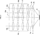
図2は、図1のようにステレオ対物レンズ6が旋回挿入された状態における、顕微鏡筐体4内のビーム路3a、3b、34の光学的構成を模式的に示す。フィルタ19a及び19bは、それぞれ、蛍光観察に関し既知の態様で作動する励起フィルタ及び吸収(阻止)フィルタである。参照符号3aは、左側ステレオ観察ビーム路(その軸線は一点鎖線で示されている。)を表し、参照符号3bは、右側ステレオ観察ビーム路(その軸線は一点鎖線で示されている。)を表す。この2つの観察ビーム路は、各フィルタ19b、ズーム光学系16a、16bを介して延在し、ステレオ対物レンズ6によって観察対象8上で合焦される。同様に、照明ビーム路34もその軸線によって示されている。照明ビーム路34は、フィルタ19a、ズーム光学系17を通過し、同様にステレオ対物レンズ6によって観察対象8上に合焦される。
FIG. 2 schematically shows an optical configuration of the
ズーム光学系16、17はすべて、可読性を高める観点からも、1つの紙面において並置して記載されているが、照明ビーム路34は、場合によっては、観察ビーム路3a、3bが延在する面と異なる面に延在することがあり、また平面図で見た場合、観察ビーム路3a、3bを部分的に覆う(重なる)こともある。ズーム光学系16a、16b、17は−それ自体既知ではあるが−機械的又は電気的に互いに結合されていることが好ましい。
The zoom
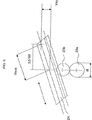
図3は、図2に示した構造(状態)の側面図であるが、図3から明らかな通り、観察部分ビーム路3bの軸線と、従って観察部分ビーム路3aの軸線は共通の面に延在する。2つの観察ビーム路3a、3bの軸線及び照明ビーム路34の軸線は、ステレオ対物レンズ6の光軸に対し平行に延在する。これら軸線3a、3b、34はすべて互いに対し所定の間隔を有する。2つの観察ビーム路3a及び3bの軸線間の距離は、図6に記号SBで示した。ステレオ対物レンズ6の光軸が延在する面は、当該面に関し2つの観察ビーム路3a、3b(の軸線)が鏡像対称的な位置関係となるような面である。
FIG. 3 is a side view of the structure (state) shown in FIG. 2. As is clear from FIG. 3, the axis of the observation
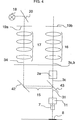
図4は、複合対物レンズ7が旋回挿入された状態にある図1に示した顕微鏡の光学的構成の模式的側面図である。照明ビーム路34の軸線は一点鎖線で示した。光源18から出発した照明ビーム路34は、例えばミラー20等の偏向要素によって偏向され、励起フィルタ19a、ズーム光学系17を通過し、照明差込入射装置15に入射する。照明差込入射装置15内では、ミラー42がビーム路をビームスプリッタ43に向かって偏向し、ビームスプリッタ43は、照明ビーム路34を、複合対物レンズ7の(射出されたビーム路3cと重なる)観察ビーム路31と重畳的に統合する。
FIG. 4 is a schematic side view of the optical configuration of the microscope shown in FIG. 1 in a state where the compound
図5は、図4の場合と同様の状態を正面図で示したものであるが、両眼ビームスプリッタ2aの一例の構造も同時に示している。図から明らかな通り、複合対物レンズ7は、左側観察ビーム路3aの延長線上に位置する。ステレオ対物レンズ6の位置に対する位置ずれ(Dislokation)を補償するために、それに応じて、顕微鏡筐体4ないしその担持装置12を左方(X方向)へ、とりわけ−紙面内において−2つの観察ビーム路3a、3bの軸線間の距離の半分の距離だけ、摺動される必要がある。また、ステレオ対物レンズ6の光軸が2つの観察ビーム路3a、3bが延在する面に存在しない場合及び/又は両眼ビームスプリッタ2aがY方向にもビームのシフト(ずれ)を引き起こす場合は、紙面に対し垂直ないし傾斜する方向(Y方向)への更なる摺動運動を行うことは有利であり、場合によっては不可欠でもある。
FIG. 5 is a front view showing the same state as in FIG. 4, but also shows an example of the structure of the
図6は、2つの摺動(シフト)成分Vsx及びVsyから構成される摺動経路(シフト)Vsを示す。図示の直線は、このシフトによって達成されるべき作用方向40を示す。作用方向40は、距離SBで互いに離隔されている2つの観察ビーム路3a、3bの軸線によって画成(規定)される面に対し角度αをなして、2つの観察ビーム路3a、3bの軸線に対して形成される。
FIG. 6 shows a sliding path (shift) Vs composed of two sliding (shift) components Vsx and Vsy. The straight line shown shows the direction of
図7は、クランクピン37及び偏心部材36を有するクランク伝動装置35を含むと共に、該偏心部材36が顕微鏡支持装置14に回動可能に支承されかつクランクピン37が担持装置12の縦孔38に嵌合されるよう構成された本発明の駆動装置10aの一例を示す。偏心部材36の支承軸41は、切換装置(レボルバないしターレット)5と固定的に結合されるため、レボルバの回転によって、偏心部材36は作動される。この偏心部材36の作動により、担持装置12は、作用方向40に応じてシフトVsに亘って摺動される。この構造の場合、回転は360°に亘って行うことができる。
FIG. 7 includes a
図8は、クランク伝送装置35を備えず、その代わりに複数の歯車ないしピニオン23a及び23bを含んで構成され、図7のものと対比されるべき装置の一例の構造を示す。但し、歯車23bは任意的に備えられる部材に過ぎない。歯車23aは、切換装置5によって駆動され、180°回転する。歯車23aの周長πdtがπdt=2sの場合、ラック24が作用方向40に駆動されることにより、所望のシフトVsが達成される。
FIG. 8 shows the structure of an example of a device that is not provided with the
図9は、複合対物レンズ7の光軸が2つの観察ビーム路3a及び3bの対称軸線と重畳(一致)する場合に、担持装置12の摺動を不要とすることを可能とするY−プリズム2bを含んだ構造の一例の模式に示す。FIG. 9 shows a Y-prism that makes it unnecessary to slide the
1 両眼観察筒
2a 両眼ビームスプリッタ
2b Y−プリズム
3 ステレオ観察ビーム路
3a 左側部分観察ビーム路
3b 右側部分観察ビーム路
3c 2つの部分観察ビーム路3a、3bが1つに統合され両眼ビームスプリッタ2から射出する(共通)ビーム路
4 顕微鏡筐体
5 切換装置
6 ステレオ対物レンズ
7 複合対物レンズ
8 観察対象
9 合焦用駆動装置
10 駆動装置
11 精細合焦装置
12 担持装置
13 スタンド
14 支持装置、顕微鏡支持装置
15 照明差込入射装置
16a、b 観察ビーム路3a、3bのズーム光学系
17 照明ビーム路34のズーム光学系
18 光源
19a 励起フィルタ
19b 吸収フィルタ
20 偏向装置ないしミラー
23a、b 歯車ないしピニオン
24 ラック
27 観察ビーム
28 落射光照明装置
30 回転軸
31 複合対物レンズの観察ビーム路
34 照明ビーム路
35 クランク伝動装置
36 偏心部材
37 クランクピン
38 縦孔
40 作用方向
41 支承軸
42 ミラーないし偏向装置
43 ビームスプリッタ
Vs シフト
Vsx X方向のシフト成分
Vsy Y方向のシフト成分
SB ステレオ観察ビーム路3a、3bの軸線間の距離
1
Vs shift Vsx Shift component in X direction Vsy Shift component in Y direction SB Distance between axes of stereo
Claims (27)
・顕微鏡筐体(4)、
・スタンド(13)に結合された合焦用駆動装置(9)と結合された顕微鏡支持装置(14)、
・前記顕微鏡支持装置(14)において前記合焦用駆動装置(9)の摺動方向に対し横断方向に該顕微鏡支持装置(14)に対し摺動可能であると共に、前記顕微鏡筐体(4)を担持するよう構成された担持装置(12)、
・2つのステレオ観察ビーム路(3a、3b)を1つの共通ビーム路(3c)に統合するための両眼ビームスプリッタ(2a)、但し、該両眼ビームスプリッタ(2a)に入射する前記2つのステレオ観察ビーム路(3a、3b)の2つの光軸と該両眼ビームスプリッタ(2a)から射出する前記共通ビーム路(3c)の光軸は互いに対し平行に延在し、かつ(射出する)該共通ビーム路(3c)の光軸は、(入射する)該2つのステレオ観察ビーム路(3a、3b)の対称中心軸線に対し、前記担持装置(12)の摺動範囲によって補償可能なシフト(Vs)を有する、
・前記顕微鏡支持装置(14)に担持され、かつ少なくとも1つのステレオ対物レンズ(6)及び少なくとも1つの複合対物レンズ(7)のための受容部を有する切換装置(5)、但し、前記ステレオ対物レンズ(6)及び前記複合対物レンズ(7)は、前記切換装置(5)の作動によって、観察対象(8)の上方において、選択的に使用可能となるよう構成され、かつ前記ステレオ対物レンズ(6)及び複合対物レンズ(7)は、何れも、前記観察対象(8)の上方において、同焦点的かつ同中心的に配置可能に構成される、及び
・前記切換装置(5)の位置に応じて自動的に前記担持装置(12)の摺動を実行するよう構成された駆動装置(10)、
を有するステレオ顕微鏡において、
前記両眼ビームスプリッタ(2a)は、前記担持装置(12)と前記複合対物レンズ(7)との間に配置されること
を特徴とするステレオ顕微鏡。・ Binocular observation tube (1),
-Microscope housing (4),
A microscope support device (14) coupled to a focusing drive device (9) coupled to a stand (13);
The microscope support device (14) is slidable relative to the microscope support device (14) in a direction transverse to the sliding direction of the focusing drive device (9), and the microscope casing (4) A carrier device (12) configured to carry
A binocular beam splitter (2a) for integrating two stereo observation beam paths (3a, 3b) into one common beam path (3c), provided that the two beams incident on the binocular beam splitter (2a) The two optical axes of the stereo observation beam path (3a, 3b) and the optical axis of the common beam path (3c) exiting from the binocular beam splitter (2a) extend in parallel to each other (and exit). The optical axis of the common beam path (3c) is a shift that can be compensated by the sliding range of the carrier device (12) with respect to the symmetry axis of the two stereo observation beam paths (3a, 3b) (incident). (Vs)
A switching device (5) carried on said microscope support device (14) and having a receiving part for at least one stereo objective lens (6) and at least one compound objective lens (7), provided that said stereo objective The lens (6) and the compound objective lens (7) are configured to be selectively usable above the observation object (8) by the operation of the switching device (5), and the stereo objective lens ( 6) and the compound objective lens (7) are both configured to be confocal and concentric above the observation object (8), and at the position of the switching device (5). A drive device (10) configured to automatically slide the carrier device (12) in response,
In a stereo microscope having
The binocular beam splitter (2a) is disposed between the carrier device (12) and the composite objective lens (7).
・両眼観察筒(1)、
・落射光照明装置又は該落射光照明装置のための差込ユニットを含む顕微鏡筐体(4)、
・スタンド(13)に結合された合焦用駆動装置(9)と結合された顕微鏡支持装置(14)、
・前記顕微鏡支持装置(14)において前記合焦用駆動装置(9)の摺動方向に対し横断方向(直交方向)に該顕微鏡支持装置(14)に対し摺動可能であると共に、前記顕微鏡筐体(4)を担持するよう構成された担持装置(12)、
・2つのステレオ観察ビーム路(3a、3b)を1つの共通ビーム路(3c)に統合するための両眼ビームスプリッタ(2a)、但し、該両眼ビームスプリッタ(2a)に入射する前記2つのステレオ観察ビーム路(3a、3b)の2つの光軸と該両眼ビームスプリッタ(2a)から射出する前記共通ビーム路(3c)の光軸は互いに対し平行に延在し、かつ(射出する)該共通ビーム路(3c)の光軸は、(入射する)該2つのステレオ観察ビーム路(3a、3b)の対称中心軸線に対し、前記担持装置(12)の摺動範囲によって補償可能なシフト(Vs)を有する、
・前記両眼ビームスプリッタ(2a)から射出する共通ビーム路(3c)に照明ビーム路(34)を差込む照明差込入射装置(15)、
・前記顕微鏡支持装置(14)に支承され、かつ少なくとも1つのステレオ対物レンズ(6)及び少なくとも1つの複合対物レンズ(7)のための受容部を有する切換装置(5)、但し、前記ステレオ対物レンズ(6)及び前記複合対物レンズ(7)は、前記切換装置(5)の作動によって、観察対象(8)の上方において、選択的に使用可能となるよう構成され、かつ前記ステレオ対物レンズ(6)及び複合対物レンズ(7)は、何れも、前記観察対象(8)の上方において、同焦点的かつ同中心的に配置可能に構成される、及び
・前記切換装置(5)の位置に応じて自動的に前記担持装置(12)の摺動を実行するよう構成された駆動装置(10)
を有するステレオ顕微鏡において、
前記2つのステレオ観察ビーム路(3a、3b)から離隔すると共に、前記ステレオ対物レンズ(6)が選択された場合該ステレオ対物レンズ(6)を通過するよう構成された照明ビーム路(34)が、前記2つのステレオ観察ビーム路(3a、3b)と並んで前記顕微鏡筐体(4)内に配されること、
を特徴とするステレオ顕微鏡。A stereo microscope configured as an epi-illumination stereo microscope,
・ Binocular observation tube (1),
A microscope housing (4) including an epi-illumination device or an insertion unit for the epi-illumination device,
A microscope support device (14) coupled to a focusing drive device (9) coupled to a stand (13);
The microscope support device (14) is slidable relative to the microscope support device (14) in a transverse direction (orthogonal direction) with respect to the sliding direction of the focusing drive device (9), and the microscope housing A carrier device (12) configured to carry a body (4);
A binocular beam splitter (2a) for integrating two stereo observation beam paths (3a, 3b) into one common beam path (3c), provided that the two beams incident on the binocular beam splitter (2a) The two optical axes of the stereo observation beam path (3a, 3b) and the optical axis of the common beam path (3c) exiting from the binocular beam splitter (2a) extend in parallel to each other (and exit). The optical axis of the common beam path (3c) is a shift that can be compensated by the sliding range of the carrier device (12) with respect to the symmetry axis of the two stereo observation beam paths (3a, 3b) (incident). (Vs)
An illumination insertion incident device (15) for inserting an illumination beam path (34) into a common beam path (3c) exiting from the binocular beam splitter (2a);
A switching device (5) supported by the microscope support device (14) and having a receiving part for at least one stereo objective lens (6) and at least one compound objective lens (7), provided that said stereo objective The lens (6) and the compound objective lens (7) are configured to be selectively usable above the observation object (8) by the operation of the switching device (5), and the stereo objective lens ( 6) and the compound objective lens (7) are both configured to be confocal and concentric above the observation object (8), and at the position of the switching device (5). A drive device (10) configured to automatically slide the carrier device (12) in response.
In a stereo microscope having
An illumination beam path (34) configured to be separated from the two stereo observation beam paths (3a, 3b) and to pass through the stereo objective lens (6) when the stereo objective lens (6) is selected. , Arranged in the microscope casing (4) alongside the two stereo observation beam paths (3a, 3b),
Stereo microscope characterized by
を特徴とする請求項2に記載のステレオ顕微鏡。The stereo microscope according to claim 2, wherein the binocular beam splitter (2a) is arranged between the carrier device (12) and the compound objective lens (7).
を特徴とする請求項1又は2に記載のステレオ顕微鏡。The sliding range of the carrier device (12) corresponding to the shift (Vs) includes a plurality of shift components (Vsx, Vsy) corresponding to a plurality of shift components (Vsx, Vsy) in at least two directions (X / Y) of one surface. The stereo microscope according to claim 1, wherein the stereo microscope has a path component.
a)前記ステレオ対物レンズ(6)を通過するか、又は
b)前記両眼ビームスプリッタ(2a)の入射軸線に重畳する
ような前記顕微鏡筐体(4)のシフト範囲に相応する、
ことを特徴とする請求項1〜4の何れか一項に記載のステレオ顕微鏡。The sliding range of the carrier device (12) is such that the two stereo observation beam paths (3a, 3b) are selectively,
a) passes through the stereo objective (6), or b) corresponds to the shift range of the microscope housing (4) such that it overlaps the incident axis of the binocular beam splitter (2a),
The stereo microscope according to any one of claims 1 to 4, wherein the stereo microscope is provided.
を特徴とする請求項5に記載のステレオ顕微鏡。In the case of a), the two axes of the two stereo observation beam paths (3a, 3b) and the axis of the stereo objective lens (6) do not extend in a common plane. The stereo microscope according to claim 5.
を特徴とする請求項1〜6の何れか一項に記載のステレオ顕微鏡。The switching device (5) is a rotation revolver or a sliding device, and the rotation axis or the sliding direction thereof extends in parallel to the common plane of the two stereo observation beam paths (3a, 3b). The stereo microscope according to any one of claims 1 to 6, wherein the stereo microscope is configured as a rotating revolver or a sliding device.
を特徴とする請求項1〜7の何れか一項に記載のステレオ顕微鏡。The microscope support device (14), the drive device (10), the slidable carrier device (12), and the switching device (5) having a plurality of objective lens receiving portions and the binocular beam splitter (2a). The stereo microscope according to any one of claims 1 to 7, wherein a single structural unit is configured to be selectively attached to and detached from the microscope casing (4).
を特徴とする請求項2〜8の何れか一項に記載のステレオ顕微鏡。The switching device (5) having the microscope support device (14), the driving device (10), the slidable carrier device (12), a plurality of objective lens receiving portions and the binocular beam splitter (2a). The illumination plug-in incidence device (15) selectively constitutes one structural unit that is configured to be detachable from the microscope casing (4). The stereo microscope according to item.
を特徴とする請求項2〜9の何れか一項に記載のステレオ顕微鏡。The compound objective lens (7) is configured to be selectable or switchable from a group of compound objective lenses by the switching device (5), or the binocular beam splitter (2a) or the illumination plug-in incident device (15). The stereo microscope according to claim 2, wherein the stereo microscope is combined.
を特徴とする請求項1〜10の何れか一項に記載のステレオ顕微鏡。The stereo microscope according to any one of claims 1 to 10, wherein the receiving portion of the compound objective lens (7) has a fine focusing device (11).
を特徴とする請求項1〜11の何れか一項に記載のステレオ顕微鏡。The stereo microscope according to any one of claims 1 to 11, wherein at least one of the plurality of receiving units includes an adjusting device capable of adjusting the objective lenses (6, 7). .
を特徴とする請求項1〜12の何れか一項に記載のステレオ顕微鏡。The stereo microscope according to claim 1, wherein the stereo objective lens is configured to be selectable or switchable from a group of stereo objective lenses.
を特徴とする請求項1〜13の何れか一項に記載のステレオ顕微鏡。The stereo microscope according to any one of claims 1 to 13, wherein the switching device (5) is configured to be rotatable over a rotation angle of 360 °.
を特徴とする請求項1〜14の何れか一項に記載のステレオ顕微鏡。The stereo microscope according to any one of claims 1 to 14, wherein the microscope support device (14) is configured in an L shape, and a portion corresponding to a short side of the L shape is fixed.
を特徴とする請求項1、3〜15の何れか一項に記載のステレオ顕微鏡。2. An epi-illumination device configured to extend an illumination beam path parallel to the two stereo observation beam paths (3 a, 3 b) in the microscope housing (4). The stereomicroscope as described in any one of 3-15.
を特徴とする請求項2〜16の何れか一項に記載のステレオ顕微鏡。The illumination plug-in incidence device (15) includes a mirror (42) and / or a beam splitter (43) disposed between the binocular beam splitter (2a) and the compound lens (7). The stereo microscope according to any one of claims 2 to 16.
を特徴とする請求項17に記載のステレオ顕微鏡。The stereo microscope according to claim 17, wherein the mirror (42) is configured to be adjustable.
を特徴とする請求項17又は18に記載のステレオ顕微鏡。The stereo microscope according to claim 17 or 18, wherein the beam splitter (43) is configured as a color neutral beam splitter.
を特徴とする請求項17又は18に記載のステレオ顕微鏡。The stereo microscope according to claim 17 or 18, wherein the beam splitter (43) is configured as a dichroic beam splitter.
を特徴とする請求項17〜20の何れか一項に記載のステレオ顕微鏡。The said beam splitter (43) is comprised as a flat structural element group which has the main boundary surface (plurality) extended in parallel with an optical branching surface, The any one of Claims 17-20 characterized by these. Stereo microscope described in 1.
を特徴とする請求項1〜21の何れか一項に記載のステレオ顕微鏡。Instead of the binocular beam splitter (2a), it has a Y-prism (2b), and the carrier device (12) and the driving device (10) are both slidable to compensate for the shift (Vs). The stereo microscope according to any one of claims 1 to 21, wherein the stereo microscope does not operate as a moving means.
を特徴とする請求項1〜21の何れか一項に記載のステレオ顕微鏡。Instead of the binocular beam splitter (2a), it has a Y-prism (2b), and the carrier device (12) and the driving device (10) are arranged in the microscope case (Y) in one spatial direction (Y). Only the position adjustment of (4) is executed, and the shift (Vsy) of the stereo objective lens (6) in the one spatial direction (Y) can be executed. The stereo microscope according to item.
を特徴とする請求項23に記載のステレオ顕微鏡。The sliding range of the carrier device (12) is such that the two stereo observation beam paths (3a, 3b) pass concentrically through the stereo objective lens (6) with respect to the compound objective lens. Corresponding to the shift range of the housing (4),
The stereo microscope according to claim 23.
を特徴とする請求項1〜24の何れか一項に記載のステレオ顕微鏡。The stereo microscope according to any one of claims 1 to 24, wherein the stereo microscope is configured as a surgical microscope that does not include an observation target support device.
を特徴とする請求項1〜25の何れか一項に記載のステレオ顕微鏡。The drive device (10) is at least one gear, each arranged or configured to cause a shift (Vs) having a shift component (Vsx, Vsy) in two spatial directions in one plane during sliding. The stereo microscope according to any one of claims 1 to 25, further comprising: a crank transmission (35) having (23a, 23b) and a rack (24) or an eccentric member (36).
顕微鏡支持装置(14)と、
駆動装置(10)と、
該駆動装置(10)によって該顕微鏡支持装置(14)に対し摺動可能な、顕微鏡筐体(4)のための担持装置(12)と、
該顕微鏡支持装置(14)によって担持されると共に、少なくとも1つのステレオ対物レンズ(6)及び少なくとも1つの複合対物レンズ(7)のための対物レンズ受容部(複数)を有する切換装置(5)と、
両眼ビームスプリッタ(2a)とを有すると共に、
前記顕微鏡支持装置(14)、前記駆動装置(10)、前記担持装置(12)、前記切換装置(5)、及び前記両眼ビームスプリッタ(2a)を全て含み、選択的にスタンド(13)の合焦用駆動装置(9)又は顕微鏡筐体(4)に着脱可能に構成された1つの構造ユニットとして構成された付加ユニット。An additional unit for a stereo microscope,
A microscope support device (14);
A driving device (10);
A carrier device (12) for the microscope housing (4) slidable relative to the microscope support device (14) by the drive device (10);
A switching device (5) carried by the microscope support device (14) and having objective lens receivers for at least one stereo objective lens (6) and at least one compound objective lens (7); ,
A binocular beam splitter (2a),
The microscope support device (14), the drive device (10), the carrier device (12), the switching device (5), and the binocular beam splitter (2a) are all included, and selectively the stand (13) An additional unit configured as one structural unit configured to be detachable from the in-focus driving device (9) or the microscope casing (4).
Applications Claiming Priority (2)
| Application Number | Priority Date | Filing Date | Title |
|---|---|---|---|
| DE20216929 | 2002-10-31 | ||
| PCT/EP2003/011346 WO2004040352A2 (en) | 2002-10-31 | 2003-10-14 | Stereomicroscope or additional element for a stereomicroscope |
Publications (3)
| Publication Number | Publication Date |
|---|---|
| JP2006504989A JP2006504989A (en) | 2006-02-09 |
| JP2006504989A5 JP2006504989A5 (en) | 2006-11-24 |
| JP4511360B2 true JP4511360B2 (en) | 2010-07-28 |
Family
ID=30469917
Family Applications (1)
| Application Number | Title | Priority Date | Filing Date |
|---|---|---|---|
| JP2004547512A Expired - Fee Related JP4511360B2 (en) | 2002-10-31 | 2003-10-14 | Stereo microscope or additional unit of stereo microscope |
Country Status (4)
| Country | Link |
|---|---|
| US (1) | US7538939B2 (en) |
| JP (1) | JP4511360B2 (en) |
| DE (1) | DE20316784U1 (en) |
| WO (1) | WO2004040352A2 (en) |
Families Citing this family (16)
| Publication number | Priority date | Publication date | Assignee | Title |
|---|---|---|---|---|
| US7224521B2 (en) | 2004-09-13 | 2007-05-29 | Cytyc Corporation | Parcentric objective |
| DE102004048302B4 (en) * | 2004-10-01 | 2017-09-07 | Carl Zeiss Microscopy Gmbh | Objective changer for stereomicroscopes and stereomicroscope |
| JP5311196B2 (en) * | 2008-09-16 | 2013-10-09 | 横河電機株式会社 | Microscope equipment |
| US9116353B2 (en) | 2008-09-16 | 2015-08-25 | Yokogawa Electric Corporation | Microscope device |
| WO2011014207A1 (en) | 2009-07-31 | 2011-02-03 | University Of Utah Research Foundation | Beam splitter module |
| US9492065B2 (en) | 2012-06-27 | 2016-11-15 | Camplex, Inc. | Surgical retractor with video cameras |
| US9642606B2 (en) | 2012-06-27 | 2017-05-09 | Camplex, Inc. | Surgical visualization system |
| DE102012024737B4 (en) | 2012-12-18 | 2023-02-16 | Carl Zeiss Microscopy Gmbh | Partcentricity correction method for zoom systems |
| WO2014189969A1 (en) | 2013-05-21 | 2014-11-27 | Camplex, Inc. | Surgical visualization systems |
| EP3046458B1 (en) | 2013-09-20 | 2020-10-21 | Camplex, Inc. | Surgical visualization systems |
| JP6521982B2 (en) | 2013-09-20 | 2019-05-29 | キャンプレックス インコーポレイテッド | Surgical visualization system and display |
| WO2016090336A1 (en) | 2014-12-05 | 2016-06-09 | Camplex, Inc. | Surgical visualization systems and displays |
| US11154378B2 (en) | 2015-03-25 | 2021-10-26 | Camplex, Inc. | Surgical visualization systems and displays |
| WO2017091704A1 (en) | 2015-11-25 | 2017-06-01 | Camplex, Inc. | Surgical visualization systems and displays |
| US10918455B2 (en) | 2017-05-08 | 2021-02-16 | Camplex, Inc. | Variable light source |
| JP7098146B2 (en) * | 2018-07-05 | 2022-07-11 | 株式会社Iddk | Microscopic observation device, fluorescence detector and microscopic observation method |
Family Cites Families (11)
| Publication number | Priority date | Publication date | Assignee | Title |
|---|---|---|---|---|
| DE3266560D1 (en) * | 1981-08-17 | 1985-10-31 | Nat Res Dev | Variable stereomicroscope |
| DE3327672C2 (en) | 1983-07-30 | 1986-02-20 | Fa. Carl Zeiss, 7920 Heidenheim | Coaxial incident light bright field illumination for stereo microscopes |
| ATE37616T1 (en) | 1984-06-29 | 1988-10-15 | Wild Heerbrugg Ag | MICROSCOPE WITH A BINOCULAR TUBE. |
| US5198927A (en) * | 1989-09-20 | 1993-03-30 | Yale University | Adapter for microscope |
| DE59606225D1 (en) * | 1995-03-02 | 2001-01-25 | Zeiss Carl Jena Gmbh | Method for generating the stereoscopic image of an object and arrangement for stereoscopic viewing |
| DE19542827A1 (en) | 1995-11-17 | 1997-05-22 | Zeiss Carl Jena Gmbh | Stereoscopic imaging system for surgical microscope |
| EP0816893A3 (en) | 1996-06-24 | 1998-09-09 | CARL ZEISS JENA GmbH | Method for creating a stereoscopic image of an object,as well as arrangement forstereoscopic viewing. |
| EP1010030B1 (en) | 1997-09-05 | 2001-11-14 | Leica Microsystems AG | Microscope, especially a fluorescence microscope, particularly a stereo fluorescence microscope |
| US7061672B2 (en) * | 2000-06-20 | 2006-06-13 | Kramer Scientific Corporation | Fluorescence microscope |
| DE10064910A1 (en) | 2000-12-23 | 2002-07-04 | Leica Microsystems | Optical viewing device |
| US6930828B2 (en) * | 2002-06-21 | 2005-08-16 | Kramer Scientific Corporation | In vitro fertilization microscope |
-
2003
- 2003-10-14 US US10/533,620 patent/US7538939B2/en not_active Expired - Lifetime
- 2003-10-14 JP JP2004547512A patent/JP4511360B2/en not_active Expired - Fee Related
- 2003-10-14 WO PCT/EP2003/011346 patent/WO2004040352A2/en active Application Filing
- 2003-10-30 DE DE20316784U patent/DE20316784U1/en not_active Expired - Lifetime
Also Published As
| Publication number | Publication date |
|---|---|
| WO2004040352A2 (en) | 2004-05-13 |
| US7538939B2 (en) | 2009-05-26 |
| US20060221441A1 (en) | 2006-10-05 |
| JP2006504989A (en) | 2006-02-09 |
| WO2004040352A3 (en) | 2004-09-30 |
| DE20316784U1 (en) | 2004-01-15 |
Similar Documents
| Publication | Publication Date | Title |
|---|---|---|
| JP4511360B2 (en) | Stereo microscope or additional unit of stereo microscope | |
| US6473229B2 (en) | Stereomicroscope | |
| US8848268B2 (en) | Microscope with light sheet illumination | |
| JP2006504989A5 (en) | ||
| US5898518A (en) | Stereo microscope arrangement | |
| JP4721981B2 (en) | Stereo microscope | |
| US6212006B1 (en) | Stereoscopic microscope | |
| US9671603B2 (en) | Optical arrangement and light microscope | |
| JP4347029B2 (en) | Stereo microscope | |
| US20060250689A1 (en) | Objective for evanescent illumination and microscope | |
| US20160170194A1 (en) | Surgical microscope having optical interfaces | |
| JP2005157335A (en) | Incident-light fluorescence stereoscopic microscope | |
| US6982825B2 (en) | Stereomicroscope | |
| US20070146872A1 (en) | Invertible light-optical microscope | |
| US7016101B2 (en) | Scanning microscope and optical element | |
| JP2004287443A (en) | Microscope, in particular stereomicroscope | |
| JP5629904B2 (en) | Stereo microscope with beam splitter device | |
| US8049958B2 (en) | Optical component for a stereomicroscope | |
| JP4532852B2 (en) | Polarization microscope and polarization observation intermediate tube | |
| JP4046525B2 (en) | Inverted microscope | |
| JP2009163200A (en) | Stereomicroscope | |
| JP2004361645A (en) | Stereoscopic microscope | |
| JP2011102817A (en) | Microscope device | |
| JPH11287956A (en) | Lens barrel for observation provided to microscope | |
| JP5023934B2 (en) | microscope |
Legal Events
| Date | Code | Title | Description |
|---|---|---|---|
| A521 | Request for written amendment filed |
Free format text: JAPANESE INTERMEDIATE CODE: A523 Effective date: 20061006 |
|
| A621 | Written request for application examination |
Free format text: JAPANESE INTERMEDIATE CODE: A621 Effective date: 20061006 |
|
| A131 | Notification of reasons for refusal |
Free format text: JAPANESE INTERMEDIATE CODE: A131 Effective date: 20100105 |
|
| A711 | Notification of change in applicant |
Free format text: JAPANESE INTERMEDIATE CODE: A711 Effective date: 20100301 |
|
| A521 | Request for written amendment filed |
Free format text: JAPANESE INTERMEDIATE CODE: A523 Effective date: 20100331 |
|
| TRDD | Decision of grant or rejection written | ||
| A01 | Written decision to grant a patent or to grant a registration (utility model) |
Free format text: JAPANESE INTERMEDIATE CODE: A01 Effective date: 20100427 |
|
| A01 | Written decision to grant a patent or to grant a registration (utility model) |
Free format text: JAPANESE INTERMEDIATE CODE: A01 |
|
| A61 | First payment of annual fees (during grant procedure) |
Free format text: JAPANESE INTERMEDIATE CODE: A61 Effective date: 20100506 |
|
| FPAY | Renewal fee payment (event date is renewal date of database) |
Free format text: PAYMENT UNTIL: 20130514 Year of fee payment: 3 |
|
| R150 | Certificate of patent or registration of utility model |
Ref document number: 4511360 Country of ref document: JP Free format text: JAPANESE INTERMEDIATE CODE: R150 Free format text: JAPANESE INTERMEDIATE CODE: R150 |
|
| R250 | Receipt of annual fees |
Free format text: JAPANESE INTERMEDIATE CODE: R250 |
|
| R250 | Receipt of annual fees |
Free format text: JAPANESE INTERMEDIATE CODE: R250 |
|
| R250 | Receipt of annual fees |
Free format text: JAPANESE INTERMEDIATE CODE: R250 |
|
| R250 | Receipt of annual fees |
Free format text: JAPANESE INTERMEDIATE CODE: R250 |
|
| R250 | Receipt of annual fees |
Free format text: JAPANESE INTERMEDIATE CODE: R250 |
|
| R250 | Receipt of annual fees |
Free format text: JAPANESE INTERMEDIATE CODE: R250 |
|
| R250 | Receipt of annual fees |
Free format text: JAPANESE INTERMEDIATE CODE: R250 |
|
| R250 | Receipt of annual fees |
Free format text: JAPANESE INTERMEDIATE CODE: R250 |
|
| R250 | Receipt of annual fees |
Free format text: JAPANESE INTERMEDIATE CODE: R250 |
|
| R250 | Receipt of annual fees |
Free format text: JAPANESE INTERMEDIATE CODE: R250 |
|
| LAPS | Cancellation because of no payment of annual fees |