EP0071925A1 - Ultraschallabtast- und Positioniereinrichtung - Google Patents
Ultraschallabtast- und Positioniereinrichtung Download PDFInfo
- Publication number
- EP0071925A1 EP0071925A1 EP82106936A EP82106936A EP0071925A1 EP 0071925 A1 EP0071925 A1 EP 0071925A1 EP 82106936 A EP82106936 A EP 82106936A EP 82106936 A EP82106936 A EP 82106936A EP 0071925 A1 EP0071925 A1 EP 0071925A1
- Authority
- EP
- European Patent Office
- Prior art keywords
- vertical support
- linkages
- scanning
- arms
- scanning apparatus
- Prior art date
- Legal status (The legal status is an assumption and is not a legal conclusion. Google has not performed a legal analysis and makes no representation as to the accuracy of the status listed.)
- Withdrawn
Links
- 230000008878 coupling Effects 0.000 claims description 14
- 238000010168 coupling process Methods 0.000 claims description 14
- 238000005859 coupling reaction Methods 0.000 claims description 14
- 230000008901 benefit Effects 0.000 description 3
- 230000005484 gravity Effects 0.000 description 3
- 230000007246 mechanism Effects 0.000 description 3
- 238000010297 mechanical methods and process Methods 0.000 description 2
- 238000000034 method Methods 0.000 description 2
- 238000006243 chemical reaction Methods 0.000 description 1
- 238000002592 echocardiography Methods 0.000 description 1
- 238000012986 modification Methods 0.000 description 1
- 230000004048 modification Effects 0.000 description 1
- 230000004044 response Effects 0.000 description 1
- 230000003068 static effect Effects 0.000 description 1
- 238000002604 ultrasonography Methods 0.000 description 1
- 238000003466 welding Methods 0.000 description 1
Images

Classifications
-
- B—PERFORMING OPERATIONS; TRANSPORTING
- B23—MACHINE TOOLS; METAL-WORKING NOT OTHERWISE PROVIDED FOR
- B23Q—DETAILS, COMPONENTS, OR ACCESSORIES FOR MACHINE TOOLS, e.g. ARRANGEMENTS FOR COPYING OR CONTROLLING; MACHINE TOOLS IN GENERAL CHARACTERISED BY THE CONSTRUCTION OF PARTICULAR DETAILS OR COMPONENTS; COMBINATIONS OR ASSOCIATIONS OF METAL-WORKING MACHINES, NOT DIRECTED TO A PARTICULAR RESULT
- B23Q11/00—Accessories fitted to machine tools for keeping tools or parts of the machine in good working condition or for cooling work; Safety devices specially combined with or arranged in, or specially adapted for use in connection with, machine tools
- B23Q11/001—Arrangements compensating weight or flexion on parts of the machine
- B23Q11/0017—Arrangements compensating weight or flexion on parts of the machine compensating the weight of vertically moving elements, e.g. by balancing liftable machine parts
-
- B—PERFORMING OPERATIONS; TRANSPORTING
- B23—MACHINE TOOLS; METAL-WORKING NOT OTHERWISE PROVIDED FOR
- B23Q—DETAILS, COMPONENTS, OR ACCESSORIES FOR MACHINE TOOLS, e.g. ARRANGEMENTS FOR COPYING OR CONTROLLING; MACHINE TOOLS IN GENERAL CHARACTERISED BY THE CONSTRUCTION OF PARTICULAR DETAILS OR COMPONENTS; COMBINATIONS OR ASSOCIATIONS OF METAL-WORKING MACHINES, NOT DIRECTED TO A PARTICULAR RESULT
- B23Q1/00—Members which are comprised in the general build-up of a form of machine, particularly relatively large fixed members
- B23Q1/25—Movable or adjustable work or tool supports
- B23Q1/44—Movable or adjustable work or tool supports using particular mechanisms
- B23Q1/50—Movable or adjustable work or tool supports using particular mechanisms with rotating pairs only, the rotating pairs being the first two elements of the mechanism
- B23Q1/54—Movable or adjustable work or tool supports using particular mechanisms with rotating pairs only, the rotating pairs being the first two elements of the mechanism two rotating pairs only
- B23Q1/5468—Movable or adjustable work or tool supports using particular mechanisms with rotating pairs only, the rotating pairs being the first two elements of the mechanism two rotating pairs only a single rotating pair followed parallelly by a single rotating pair
-
- G—PHYSICS
- G10—MUSICAL INSTRUMENTS; ACOUSTICS
- G10K—SOUND-PRODUCING DEVICES; METHODS OR DEVICES FOR PROTECTING AGAINST, OR FOR DAMPING, NOISE OR OTHER ACOUSTIC WAVES IN GENERAL; ACOUSTICS NOT OTHERWISE PROVIDED FOR
- G10K11/00—Methods or devices for transmitting, conducting or directing sound in general; Methods or devices for protecting against, or for damping, noise or other acoustic waves in general
- G10K11/18—Methods or devices for transmitting, conducting or directing sound
- G10K11/26—Sound-focusing or directing, e.g. scanning
- G10K11/35—Sound-focusing or directing, e.g. scanning using mechanical steering of transducers or their beams
- G10K11/352—Sound-focusing or directing, e.g. scanning using mechanical steering of transducers or their beams by moving the transducer
Definitions
- This invention relates generally to ultrasonic scanners such as used for medical diagnostic purposes, and more particularly the invention relates to an improved structure for positioning an ultrasonic scanner with respect to a patient.
- Ultrasonic diagnostic systems are known and commercially available for diagnostic purposes. See for example U.S. Patent No. 4,172,386 for "Video A Trace Display System for Ultrasonic Diagnostic System” and U.S. Patent No. 4,204,433 for "Computerized Ultrasonic Scanner With Technique Select”.
- the commercially available Datason ultrasound system of General Electric Company provides both real time and static images on a television display.
- such systems utilize sound transducers to transmit ultrasonic (e.g. on the order of several megahertz) waves into a patient and to receive echo signals.
- the transducer is attached to a plurality of hinged arms for movement in a single plane, and potentiometers associated with the hinged arms produce signals which identify the transducer position.
- a transducer array or a hand held transducer can be used.
- the echo signals are applied to a time gain compensated amplifier to adjust the echo signals for attenuation in passing through the patient.
- the adjusted signals are then passed through an analog to digital conversion and video processing circuitry and thence to scan converter circuitry for display formatting.
- the display comprises a plurality of pixels in horizontal rows and vertical columns with each pixel having a brightness level in response to the input signal.
- the brightness is defined by a 32 level Gray-scale, hence the pixel brightness level requires a five bit digital code.
- the transducer which transmits the ultrasonic wave into a patient and receives echos therefrom is typically mounted on an articulated arm which extends from a support column.
- the operator Using the articulated arm assembly, the operator must be able to position the transducer over a patient easily and with accuracy.
- a common method of positioning the transducer in the horizontal plane is to use two horizontal support arms joined by vertical pivots between the support column and the articulated arm assembly. When the horizontal support arms are at full extension, the overhung load require: that the support column have a base support of sufficient size to prevent tipping over of the apparatus. Additionally, a vertical height adjustment is required in the apparatus.
- an object of the present invention is an improved ultrasonic scanner.
- Another object of the invention' is an improved mechanical positioning assembly for use in an ultrasonic scanner and like apparatus.
- scanning apparatus in accordance with the invention includes a vertical support, a positionable scanning means, and first mechanical coupling means for attaching the positionable scanning means to the vertical support.
- the mechanical coupling means includes first and second linkages, means for pivotally attaching said first and second linkages to said vertical support, and means for pivotally attaching said first and second linkages to said positionable scanning means whereby said positionable scanning means can be moved vertically by pivoting said first and second linkages.
- the scanning apparatus further includes counter-balance means attached to the vertical support and moveable with the first mechanical coupling means.
- the counter-balance means is attached to the vertical support by second mechanical coupling means comprising third and fourth linkages, means for pivotally attaching the third and fourth linkages to the vertical support and means for pivotally attaching the third and fourth linkages to the counter-balance means.
- the third linkage comprises an extension of the first linkage whereby the first coupling means and the second coupling means move in unison.
- the counter-balance load remains constant regardless of extension of the positionable scanning means.
- first and second linkages comprise U-shaped brackets and the first linkage further includes a tubular support member within the U-shaped bracket for supporting torsion loads.
- Figure 1 is a diagrammatic perspective illustration of ultrasonic scanning apparatus including a transducer 10 and articulated arm shown generally at 12 which are mounted to a vertical support column 14 by means of horizontal support arms 16 and 18.
- the support arms 16 and 18 are pivotally attached as indicated by the arrows whereby the transducer 10 and articulated arm 12 can be variably positioned in a horizontal plane.
- brakes are used at the pivot points to provide a stable scan plane.
- the vertical support 14 must have a sufficient base support area shown generally at 20 to present a tipover of the apparatus when the horizontal arms 16 and 18 are fully extended. Further, the apparatus must have a mechanism for moving the transducer/articulated arm assembly vertically, and in the illustrated embodiment this is accomplished by a drive motor 22 which moves the vertical support 14 vertically.
- a drive motor 22 which moves the vertical support 14 vertically.
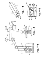
- FIG. 2 is a diagrammatic illustration of a scanning apparatus and positioning system in accordance with the present invention in which the transducers/articulated arm shown generally at 30 and the horizontal support arms 32, 33 are mounted to the vertical support 34 by means of parallel and equal length linkages 36 and 38 which are pivotally attached to the vertical support 34 as shown at 40 and pivotally attached to a bracket 42 depending from the support arm 32 as shown at 44.
- the parallel and equal length arms 36 and 38 together with the vertical post 34 and the bracket 42 comprise a four-bar linkage whereby the transducer/articulated arm assembly 30 can be moved vertically with the horizontal arms 32, 33 remaining horizontal as illustrated by dotted lines.
- a suitable counterweight 46 is provided by an extension of the arm 38 to counterbalance the horizontal arms 32, 33 and the transducer/articulated arm assembly.
- the four-bar linkage effectively establishes a center of gravity of the horizontal bars 32, 33 and assembly 30 at the pivotal points 44 without regard to the horizontal position of arms 32, 33.
- the counterweight 46 provides a constant counterbalance whether the horizontal arm 32 is fully extended or not. Accordingly, an operator of the system can manually move the assembly vertically without regard to the horizontal position of the transducer/ articulated arm 30.
- the system of Figure 2 can be.modified as shown in Figure 3 whereby the counterweight is connected to the extension of linkage 38 by linkage 49 and is mounted to the vertical support 34 by a second four-bar linkage including the parallel and equal length arms 48 and 50 which are pivotally mounted to the counterweight 46 and the vertical post 34.
- the counterweight 46 can be positioned more closely to the vertical post 34 and minimize the space required for the scanning apparatus.
- the four-bar linkage whereby the effective center of gravity of the horizontally extended transducer/articulated arm assembly remains at the pivot points 44, the fixed base or "footprint" of the vertical support 34 is minimized.
- the horizontal support arms can be raised and lowered while maintaining horizontal alignment.
- the lower connecting link can be designed to take the full moment load or torsion thereby allowing the upper link to carry only tension.
- using a four-bar linkage for counterbalancing allows the counter- balance load to remain constant and closely mounted to the vertical support.
- the center of gravity of the assembly is significantly lowered. Accordingly, the articulated arm can be positioned both horizontally and vertically by applying minimal forces to a single point on the articulated arm support.
Landscapes
- Engineering & Computer Science (AREA)
- Mechanical Engineering (AREA)
- Physics & Mathematics (AREA)
- Acoustics & Sound (AREA)
- Multimedia (AREA)
- Ultra Sonic Daignosis Equipment (AREA)
- Investigating Or Analyzing Materials By The Use Of Ultrasonic Waves (AREA)
Applications Claiming Priority (2)
| Application Number | Priority Date | Filing Date | Title |
|---|---|---|---|
| US06/290,837 US4548374A (en) | 1981-08-07 | 1981-08-07 | Ultrasonic scanning apparatus and positioning system |
| US290837 | 1981-08-07 |
Publications (1)
| Publication Number | Publication Date |
|---|---|
| EP0071925A1 true EP0071925A1 (de) | 1983-02-16 |
Family
ID=23117755
Family Applications (1)
| Application Number | Title | Priority Date | Filing Date |
|---|---|---|---|
| EP82106936A Withdrawn EP0071925A1 (de) | 1981-08-07 | 1982-07-31 | Ultraschallabtast- und Positioniereinrichtung |
Country Status (3)
| Country | Link |
|---|---|
| US (1) | US4548374A (de) |
| EP (1) | EP0071925A1 (de) |
| JP (1) | JPS5844045A (de) |
Cited By (1)
| Publication number | Priority date | Publication date | Assignee | Title |
|---|---|---|---|---|
| CN103006257A (zh) * | 2011-09-27 | 2013-04-03 | 深圳迈瑞生物医疗电子股份有限公司 | 一种显示设备支撑装置及其超声诊断仪 |
Families Citing this family (20)
| Publication number | Priority date | Publication date | Assignee | Title |
|---|---|---|---|---|
| DE8530047U1 (de) * | 1985-10-23 | 1986-05-15 | Ncr Corp., Dayton, Ohio | Ausziehbarer, höhenverstellbarer Schwenkarm für Bildschirmgeräte od. dgl. |
| DE4202922A1 (de) * | 1992-02-01 | 1993-08-05 | Zeiss Carl Fa | Motorisches stativ |
| DE4334069A1 (de) * | 1993-06-21 | 1995-04-13 | Zeiss Carl Fa | Ausbalancierbares Stativ |
| US6224026B1 (en) | 1999-05-05 | 2001-05-01 | N/A | Overhead articulated support for the human arm |
| US10219815B2 (en) | 2005-09-22 | 2019-03-05 | The Regents Of The University Of Michigan | Histotripsy for thrombolysis |
| JP2009056210A (ja) * | 2007-09-03 | 2009-03-19 | Ge Medical Systems Global Technology Co Llc | 超音波診断装置 |
| US20090062657A1 (en) * | 2007-08-31 | 2009-03-05 | Koji Yanagihara | Ultrasonic diagnostic apparatus |
| JP2009201967A (ja) * | 2008-01-31 | 2009-09-10 | Ge Medical Systems Global Technology Co Llc | 超音波診断装置 |
| JP2009178346A (ja) * | 2008-01-31 | 2009-08-13 | Ge Medical Systems Global Technology Co Llc | 超音波診断装置 |
| JP2009240342A (ja) * | 2008-03-28 | 2009-10-22 | Ge Medical Systems Global Technology Co Llc | 超音波診断装置 |
| DE102012209594B3 (de) * | 2012-06-06 | 2013-06-06 | Leica Microsystems (Schweiz) Ag | Stativ |
| WO2015003154A1 (en) * | 2013-07-03 | 2015-01-08 | Histosonics, Inc. | Articulating arm limiter for cavitational ultrasound therapy system |
| US10780298B2 (en) | 2013-08-22 | 2020-09-22 | The Regents Of The University Of Michigan | Histotripsy using very short monopolar ultrasound pulses |
| US11135454B2 (en) | 2015-06-24 | 2021-10-05 | The Regents Of The University Of Michigan | Histotripsy therapy systems and methods for the treatment of brain tissue |
| CN120324803A (zh) | 2018-11-28 | 2025-07-18 | 希斯托索尼克斯公司 | 组织摧毁术系统及方法 |
| WO2021155026A1 (en) | 2020-01-28 | 2021-08-05 | The Regents Of The University Of Michigan | Systems and methods for histotripsy immunosensitization |
| US12527976B2 (en) | 2020-06-18 | 2026-01-20 | Histosonics, Inc. | Histotripsy acoustic and patient coupling systems and methods |
| AU2021332372A1 (en) | 2020-08-27 | 2023-03-16 | The Regents Of The University Of Michigan | Ultrasound transducer with transmit-receive capability for histotripsy |
| US20240149078A1 (en) | 2022-10-28 | 2024-05-09 | Histosonics, Inc. | Histotripsy systems and methods |
| US12446905B2 (en) | 2023-04-20 | 2025-10-21 | Histosonics, Inc. | Histotripsy systems and associated methods including user interfaces and workflows for treatment planning and therapy |
Citations (4)
| Publication number | Priority date | Publication date | Assignee | Title |
|---|---|---|---|---|
| DE1077579B (de) * | 1959-07-04 | 1960-03-10 | Heinrich Waas Dipl Ing | Einrichtung zur Wassertiefenmessung nach dem Echolotverfahren |
| US3255893A (en) * | 1963-07-10 | 1966-06-14 | Gen Mills Inc | Manipulator boom system |
| US4065976A (en) * | 1976-09-20 | 1978-01-03 | Stanford Research Institute | Mechanical scanning method and apparatus for ultrasonic imaging, or the like |
| US4196630A (en) * | 1978-05-18 | 1980-04-08 | Rudolph Dale C | Overhead arm assembly |
Family Cites Families (16)
| Publication number | Priority date | Publication date | Assignee | Title |
|---|---|---|---|---|
| FR742471A (de) * | 1933-03-08 | |||
| BE562676A (fr) * | 1957-11-25 | 1957-12-14 | Support pantographique pour foreuses et autres outils de travail portatifs. | |
| US476739A (en) * | 1892-06-07 | Electric-street-lamp post | ||
| US911935A (en) * | 1908-05-23 | 1909-02-09 | Fletcher T Smallwood | Rural mail-box. |
| US1140051A (en) * | 1914-08-27 | 1915-05-18 | Henry Macnaughton Macnaughton-Jones | Adjustable support or bracket for lamps, shades, mirrors, or the like. |
| US1711768A (en) * | 1925-12-03 | 1929-05-07 | Bausch & Lomb | Lens-focusing mechanism |
| GB499061A (en) * | 1938-04-22 | 1939-01-18 | Henry Macnaughton Macnaughton | Improvements in or relating to adjustable supports for lamps, mirrors or the like |
| GB554340A (en) * | 1941-11-25 | 1943-06-30 | Walter Raylor | Improvements in building constructions |
| US2548476A (en) * | 1944-11-17 | 1951-04-10 | Horstma Kathleen Mary E Quicke | Bracket |
| GB615384A (en) * | 1946-08-07 | 1949-01-05 | Frederick George Horstmann | An improved mounting, more particularly for inspection lamps and the like |
| US3498577A (en) * | 1968-05-31 | 1970-03-03 | Edna Anne Mehr | Adjustable bracket structure |
| US3783262A (en) * | 1973-04-03 | 1974-01-01 | Us Army | Portable surgical lamp |
| US4241891A (en) * | 1979-04-06 | 1980-12-30 | Unirad Corporation | Overhead arm assembly |
| DE7930125U1 (de) * | 1979-07-24 | 1980-01-24 | Contraves Ag, Zuerich (Schweiz) | Zusatzvorrichtung an einem stativ fuer ein optisches beobachtungsgeraet |
| DE7930126U1 (de) * | 1979-07-24 | 1980-01-24 | Contraves Ag, Zuerich (Schweiz) | Stativ fuer ein optisches beobachtungsgeraet |
| US4266747A (en) * | 1979-07-26 | 1981-05-12 | Positioning Devices, Incorporated | Equipoised articulated support arm |
-
1981
- 1981-08-07 US US06/290,837 patent/US4548374A/en not_active Expired - Fee Related
-
1982
- 1982-07-31 EP EP82106936A patent/EP0071925A1/de not_active Withdrawn
- 1982-08-06 JP JP57136450A patent/JPS5844045A/ja active Pending
Patent Citations (4)
| Publication number | Priority date | Publication date | Assignee | Title |
|---|---|---|---|---|
| DE1077579B (de) * | 1959-07-04 | 1960-03-10 | Heinrich Waas Dipl Ing | Einrichtung zur Wassertiefenmessung nach dem Echolotverfahren |
| US3255893A (en) * | 1963-07-10 | 1966-06-14 | Gen Mills Inc | Manipulator boom system |
| US4065976A (en) * | 1976-09-20 | 1978-01-03 | Stanford Research Institute | Mechanical scanning method and apparatus for ultrasonic imaging, or the like |
| US4196630A (en) * | 1978-05-18 | 1980-04-08 | Rudolph Dale C | Overhead arm assembly |
Cited By (2)
| Publication number | Priority date | Publication date | Assignee | Title |
|---|---|---|---|---|
| CN103006257A (zh) * | 2011-09-27 | 2013-04-03 | 深圳迈瑞生物医疗电子股份有限公司 | 一种显示设备支撑装置及其超声诊断仪 |
| CN103006257B (zh) * | 2011-09-27 | 2015-09-16 | 深圳迈瑞生物医疗电子股份有限公司 | 一种显示设备支撑装置及其超声诊断仪 |
Also Published As
| Publication number | Publication date |
|---|---|
| US4548374A (en) | 1985-10-22 |
| JPS5844045A (ja) | 1983-03-14 |
Similar Documents
| Publication | Publication Date | Title |
|---|---|---|
| US4548374A (en) | Ultrasonic scanning apparatus and positioning system | |
| US4625731A (en) | Ultrasonic image display mounting | |
| US4356731A (en) | Method and means for generating time gain compensation control signal for use in ultrasonic scanner and the like | |
| US4501011A (en) | Angulating lateral fluoroscopic suspension | |
| US5475885A (en) | Couch system for x-ray diagnosis | |
| CN208640736U (zh) | 一种可以实现变形及横移补偿的ct检查床 | |
| US5159622A (en) | X-ray fluoroscopic imaging apparatus with extended imaging set up range | |
| US4634335A (en) | Elongate, transportable unit standing upright during use | |
| CA2139422A1 (en) | Automated longitudinal position translator for ultrasonic imaging probes, and method of using same | |
| SE9203643D0 (sv) | Undersoekningsbord | |
| WO2000075010A8 (en) | Device for positioning and lifting a marine structure, particularly a platform deck | |
| US3547101A (en) | Medical ultrasonic diagnostic system | |
| JPH1014911A (ja) | 画像診断装置用寝台 | |
| US4715591A (en) | Patient support for radiation imaging | |
| JP2869740B2 (ja) | 高架橋点検装置 | |
| RU98112760A (ru) | Установка для рентгенологического исследования, оснащенная наклонным столом | |
| US4635284A (en) | X-ray examination apparatus comprising a C-shaped or U-shaped support for the X-ray source and detector | |
| US4365345A (en) | Servo operated fluoroscopic table | |
| CN2553353Y (zh) | 超声功率测量装置 | |
| US5372043A (en) | Method and apparatus for ultrasonic inspection of curved nacelle components | |
| US4879737A (en) | Articulated X-ray stand arm | |
| US4467273A (en) | Interchangeable component identification system | |
| CN219557341U (zh) | 一种医疗设备 | |
| CN213665358U (zh) | 超声检查辅助架 | |
| CN1112821A (zh) | 带有一个双杠杆的医疗器械 |
Legal Events
| Date | Code | Title | Description |
|---|---|---|---|
| PUAI | Public reference made under article 153(3) epc to a published international application that has entered the european phase |
Free format text: ORIGINAL CODE: 0009012 |
|
| AK | Designated contracting states |
Designated state(s): DE GB NL |
|
| 17P | Request for examination filed |
Effective date: 19830726 |
|
| STAA | Information on the status of an ep patent application or granted ep patent |
Free format text: STATUS: THE APPLICATION HAS BEEN WITHDRAWN |
|
| 18W | Application withdrawn |
Withdrawal date: 19850502 |
|
| RIN1 | Information on inventor provided before grant (corrected) |
Inventor name: THOMPSON, CRAIG ROBERT Inventor name: NAUMANN, THEODORE FLEIDNER, JR. |