EP0071663A2 - Circuit intégré pour la régulation de tension d'alimentation selon le principe de commutation pour des appareils de télévision - Google Patents
Circuit intégré pour la régulation de tension d'alimentation selon le principe de commutation pour des appareils de télévision Download PDFInfo
- Publication number
- EP0071663A2 EP0071663A2 EP81106182A EP81106182A EP0071663A2 EP 0071663 A2 EP0071663 A2 EP 0071663A2 EP 81106182 A EP81106182 A EP 81106182A EP 81106182 A EP81106182 A EP 81106182A EP 0071663 A2 EP0071663 A2 EP 0071663A2
- Authority
- EP
- European Patent Office
- Prior art keywords
- input
- counter
- output
- voltage
- flop
- Prior art date
- Legal status (The legal status is an assumption and is not a legal conclusion. Google has not performed a legal analysis and makes no representation as to the accuracy of the status listed.)
- Granted
Links
Images


Classifications
-
- H—ELECTRICITY
- H02—GENERATION; CONVERSION OR DISTRIBUTION OF ELECTRIC POWER
- H02M—APPARATUS FOR CONVERSION BETWEEN AC AND AC, BETWEEN AC AND DC, OR BETWEEN DC AND DC, AND FOR USE WITH MAINS OR SIMILAR POWER SUPPLY SYSTEMS; CONVERSION OF DC OR AC INPUT POWER INTO SURGE OUTPUT POWER; CONTROL OR REGULATION THEREOF
- H02M3/00—Conversion of DC power input into DC power output
- H02M3/22—Conversion of DC power input into DC power output with intermediate conversion into AC
- H02M3/24—Conversion of DC power input into DC power output with intermediate conversion into AC by static converters
- H02M3/28—Conversion of DC power input into DC power output with intermediate conversion into AC by static converters using discharge tubes with control electrode or semiconductor devices with control electrode to produce the intermediate AC
- H02M3/325—Conversion of DC power input into DC power output with intermediate conversion into AC by static converters using discharge tubes with control electrode or semiconductor devices with control electrode to produce the intermediate AC using devices of a triode or a transistor type requiring continuous application of a control signal
- H02M3/335—Conversion of DC power input into DC power output with intermediate conversion into AC by static converters using discharge tubes with control electrode or semiconductor devices with control electrode to produce the intermediate AC using devices of a triode or a transistor type requiring continuous application of a control signal using semiconductor devices only
- H02M3/33507—Conversion of DC power input into DC power output with intermediate conversion into AC by static converters using discharge tubes with control electrode or semiconductor devices with control electrode to produce the intermediate AC using devices of a triode or a transistor type requiring continuous application of a control signal using semiconductor devices only with automatic control of the output voltage or current, e.g. flyback converters
- H02M3/33515—Conversion of DC power input into DC power output with intermediate conversion into AC by static converters using discharge tubes with control electrode or semiconductor devices with control electrode to produce the intermediate AC using devices of a triode or a transistor type requiring continuous application of a control signal using semiconductor devices only with automatic control of the output voltage or current, e.g. flyback converters with digital control
Definitions
- the invention relates to integrable circuit arrangements for regulating DC supply voltages according to the switching regulator principle in television sets, a power semiconductor component being periodically switched on and off by a signal which is pulse-width-modulated as a function of a nominal / actual comparison which is synchronized line-by-line during each line duration, cf. . the preamble of claim 1.
- Switching regulators of this type for general use with a pulse-width-modulated control signal for the power semiconductor component which is to be switched on and off periodically are already known in an integrated form, cf. for example the magazine "Electronic Design", February 1, 1979, pp. 102 and 18 January 1980, pp. 94-101.
- the switching regulators shown generate the pulse-width-modulated control signal in the manner of analog circuits, i.e. that is, depending on the actual / target comparison, the pulse width can be changed continuously.
- a sawtooth generator is also provided, which serves as a reference voltage when generating the pulse-width-modulated control signal. This sawtooth generator has a synchronizing input in the second reference.
- DE-OS 28 43 988 it is known from DE-OS 28 43 988 to also build control circuits based on the switching regulator principle in such a way that the pulse-width-modulated control signal is generated on the basis of digital circuit principles.
- a microprocessor is used for this purpose, which, starting from a clock signal, generates the pulse-width-modulated signal in steps of this clock frequency.
- the object of the invention is therefore to develop the integrated switching regulators known from the magazine "Electronic Design” using the digital principles obtained from the aforementioned DE-OS in such a way that they are suitable for use in television sets.
- those partial aspects of the arrangement according to DE-OS are to be used which are applicable in the sense of solving this task.
- no element protection is claimed for this.
- the solution to the problem thus consists in measures known in part from DE-OS and the other means specified in the characterizing part of claim 1. To solve the task, is therefore from using a microprocessor.
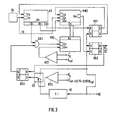
- Fig. 1 the construction of a television power supply unit using a switching regulator, which is conventional in principle, is shown.
- the essential parts of this basic circuit diagram are provided with reference numerals.
- the mains voltage U N is applied to the primary winding of a main transformer via a rectifier bridge and the power semiconductor component TL.
- Another small transformer feeds another rectifier, from which the operating voltage for the switching regulator is taken.
- the network side is completely galvanically isolated from the DC voltage side, as required by the VDE standards.
- the semiconductor component TL ' is shown, which is controlled by the pulse width modulator PWM and acts on the power semiconductor component TL in a known manner via the associated further transformer.
- known flyback converter principle generates corresponding AC voltages, which result in rectified, the regulated voltages U g and U gg .
- the voltage proportional to this becomes removed and fed to the pulse width modulator PWM as information about the actual value.
- the load current I L flowing in the load circuit is measured by means of the current measuring resistor RI1 and the voltage drop resulting therefrom is also supplied to the pulse width modulator as current information U.
- the tap for the current signal U. ie the connection point between the secondary windings and the current measuring resistor RI1, is connected to the regulated voltage U g via the resistor RI2, so that this connection point is fixed in terms of potential.
- FIG. 1 also shows the clock generator TG, the output signal of which is fed to the pulse width modulator PWM as a clock signal TS, as well as the horizontal synchronizing pulses HZ originating from the synchronizing signal separation stage SS of the television set.
- a clock oscillator for example, is a quartz oscillator with four times the color subcarrier frequency of color television sets, an oscillator with an oscillation frequency of 17.7 MHz.
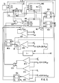
- the setpoint / actual comparison is carried out by the first digital comparator stage KS1, at the first input of which the reference voltage U ref and at the second input of which the voltage U 9 proportional to the regulated voltage U 9 according to FIG. 1 is present.
- the reference voltage U ref can be generated in any of the known ways, for example by means of a Z-diode or a temperature-compensated Z-diode.
- the first digital comparator KS1 produces at its output only a binary signal, the two values, that is, a positive voltage value assigned to H-level, and a one to lower voltage value associated with the L level, the two input si g nal Schemeen U ref> or U ref ⁇ assigned.
- control amplifier used in conventional analog control circuits is replaced by the comparator stage, which only supplies a binary signal regarding the fact that the reference voltage U ref falls below or exceeds the actual value in the form of the voltage U '.
- the further digital comparator stages to be added in the further exemplary embodiments and further developments are also stages of this type with a binary signal output.
- the clock generator TG is connected to the counting input Ez of the up counter VZ of the counting capacitance n and to the counting input Ez of the preselection counter VWZ.
- the pulses of the clock signal TS are therefore counted by means of these two counters during certain times to be described.
- the counter reading output Azg is at the counter input Ez of the up / down counter, which thus counts these output pulses of the up counter VZ either in the up or down direction, the output signal of the first comparator stage KS1 defining the counting direction via the changeover input Evr for up or down counting.
- the counter outputs Az of the up / down counter VRZ are connected in parallel to the preselection inputs Ev of the preselection counter VWZ, which is indicated by the band-like arrow in FIG. 2.
- the counter reading reached at certain times in the up / down counter VRZ is thus read into the preselection counter VWZ and is used there to determine the duration of a counting cycle.
- the preselection counter VWZ can either be an up counter that counts from the preselected counter reading up to a certain higher counter reading and then emits an impulse at this counter reading output as a zero crossing output, or it can be a down counter that counts down to zero from the preselected counter reading and then delivers a zero crossing output pulse.
- the take-over input Eu of the preselection counter VWZ is at one of the other counter reading outputs, namely the output Azk, of the up-counter VZ. If this counter has thus reached the counter reading k, the counter reading reached in the up / down counter at this point in time is adopted as the preselection counter reading in the preselection counter VWZ.
- the nth counter output Azn of the up counter VZ is connected to the R input of the first RS flip-flop RS1, the Q output of which lies at the start and enable input Es of the up-counter VZ, while the Q output is connected to the start and enable input Es of the preselection counter VWZ.
- the horizontal synchronizing pulses HZ are located at the S input of the first RS flip-flop RS1.
- the first RS flip-flop RS1 is set, and the up counter VZ is started by the corresponding Q signal.
- the first RS flip-flop RS1 is reset again, so that on the one hand the up counter VZ cannot continue counting but on the other hand the preset counter VWZ is now started via the Q signal.
- the zero crossing output of the preselection counter VWZ is connected to the R input of the second RS flip-flop RS2, at whose S input the horizontal pulses HZ are connected.
- This flip-flop like the flip-flop RS1, is therefore set by each horizontal pulse and is reset when the preselection counter VWZ reaches zero.
- a pulse which is the pulse width modulated pulse for driving the Leistun g .leiterbauelements TL is formed.
- This drive pulse is thus composed in time of a first part, which is predetermined by the counting capacity n of the up-counter VZ, and of a second part, which is determined by the counter reading given at the time of transfer by the counter reading of the up / down counter.
- the pulse width modulated The signal therefore has a minimum pulse width specified by the up-counter VZ and a maximum pulse width which is determined by the counting capacities of the up-counter VZ and the up / down counter VRZ.
- the counting capacities of the three counters VZ, VWZ, VRZ are selected taking into account the frequency of the clock generator TG and the line duration so that the maximum pulse width of the pulse width modulated signal covers a certain part of the line duration, e.g. B. 44 ⁇ s, does not exceed.
- FIG. 3 shows a further development of the arrangement according to FIG. 2, which contains additional circuit parts for the start-up phase of the switching regulator after the mains voltage has been switched on.
- the second digital comparator stage KS2 is provided, which measures the voltage with a reference voltage compares, which is approximately 0.75 to 0.95 times the reference voltage U ref . So is the voltage proportional to the regulated voltage U 9 5 to 25% below their nominal value, the second comparator stage KS2 emits one binary signal level and above this range the other binary signal level.
- These two signal levels control the changeover contact of the electronic switch ES, the output of which is at the S input of the third RS flip-flop RS3.
- At one input of the switch ES are the horizontal synchronizing pulses HZ and at the other the output of the frequency divider BT, the input of which is also supplied with the horizontal synchronizing pulses HZ.
- the R input of the third RS flip-flop RS3 is connected to the Q output of the second RS flip-flop RS2 and is therefore supplied with the pulse-width-modulated pulse.
- the Q output The third RS flip-flop RS3 is located at an input of the first AND gate UG1, which is inserted with its other input-output path into the connecting line between the counter reading output Azg of the up-counter VZ and the counting input Ez of the up / down counter VRZ.
- the third RS flip-flop RS3 is set by the number of horizontal pulses reduced by the divider factor of the frequency divider BT.
- the counting pulses to the up / down counter are passed through the first AND gate UG1.
- the change in its counter reading Az thus takes place much more slowly, ie the pulse-width-modulated signal is not changed during the start-up phase for the duration of each line, but only during every r-th line if the divisor of the frequency divider BT is designated by r.
- FIG. 4 shows a further development of the arrangement according to FIG. 3, which relates to the additional circuit parts compared to FIG. 3, the third digital comparator stage KS3 and the first OR gate OG1.
- These two too Additional circuit parts can, however, also be provided in the arrangement according to FIG. 2, ie without the additional circuit parts in FIG. 3. They relate to the measuring circuit short-circuit protection of the control circuit and can therefore also be used regardless of the use of the start-up circuit according to FIG.
- the third comparator stage KS3 compares the voltage proportional to the regulated voltage U g with the fixed voltage U of a first voltage threshold, which is approximately 0.1 to 0.2 times the reference voltage U ref .
- the output signal of the third comparator stage KS3 is fed to the up / down counter VRZ now equipped with the reset input Er and also via the first OR gate OG1 also to the R input of the second RS flip-flop RS2.
- the other input-output path of the first OR gate OG1 is inserted into the connecting line between the zero crossing output An of the preselection counter VWZ and the R input of the second RS flip-flop RS2.
- the output signal of the third comparator stage KS3 resets the up / down counter to its zero position and thus ensures that the preset counter also returns to its zero position after the next transfer pulse reached.
- this output pulse from the third comparator stage KS3 also resets the second RS flip-flop RS2, which determines the duration of the pulse-width-modulated signal, and the output pulse duration is thereby immediately reduced to the minimum duration.
- This type of control loop protection is effective immediately after the short circuit occurs and is also maintained for the duration of the short circuit. Furthermore, the short-circuit protection automatically becomes ineffective after the short circuit has ceased to exist, that is to say the operation of a so-called electronic fuse with automatic reclosure is present.
- FIG. 5 shows a further development of the arrangement according to FIG. 4, which in addition to the control loop protection also represents protection in the event of a short circuit and current overload of the power supply unit output voltage.
- the additional circuit parts compared to FIG. 4 are provided, namely the fourth and fifth digital comparator stages KS4 and KS5, the fourth RS flip-flop RS4, the second and the third OR gate OG2, OG3 and the second and the third AND gate UG2, UG3.
- the second OR gate OG2 can be omitted if the control loop protection is not provided by means of the third comparator stage KS3.
- the fourth and fifth comparator stages KS4, KS5 compare the fixed voltage U of the first voltage threshold and the fixed voltage, respectively a second voltage threshold each with the load current proportional voltage U i , cf. Fig. 1.
- the fixed tension the second voltage threshold is 0.25 to 0.4 times the reference voltage U ref .
- the output of the fourth comparator stage KS4 is OR-linked to that of the third comparator stage KS3 via the second OR gate OG2 and thus leads to the reset input Er of the up / down counter VRZ. So the load current exceeds one of the second voltage threshold If the value is correct, the control is immediately reduced to the minimum pulse width of the pulse-width-modulated signal, as in the short-circuit case of the control loop described above.
- the fifth comparator stage KS5 is used in a load current range between the maximum load current specified by the first voltage threshold U s and that by the second voltage threshold predetermined load current achieved a gradual reduction in the pulse width of the pulse width modulated signal.
- the fifth comparator stage KS5 compares the fixed voltage value the second voltage threshold with the load current-dependent voltage U i .
- the output of the fifth comparator stage KS5 is connected to the S input of the fourth RS flip-flop RS4, the R input of which is connected to the Q output of the first RS flip-flop RS1.
- the Q output of the fourth RS flip-flop RS4 is connected to one input of the second AND gate UG2, the other input of which is connected to a further counter output Azj of the up-counter VZ and the output of which is connected to an input of the third OR gate OG3. This is inserted with its other input-output path into the connecting line between the output of the first AND gate UG1 and the counting input Ez of the up / down counter.
- the counting input Ez of the up / down counter VRZ is supplied with the additional pulse at the counter reading output Azj of the upstream counter VZ in addition to the output pulse at the counter reading output Azg. ie the Up / down counter is counted at double frequency in the reverse direction. In each line, the pulse width reduction rate is twice as high as in normal control mode.
- the Q output of the fourth RS flip-flop RS4 is AND-linked to the output signal of the first comparator stage KS1 by means of the third AND gate UG3. that is, regardless of the output signal of the comparator stage KS1, the up / down counter VRZ can count only as long as a current exceeding proportional to the U1 threshold is determined by the comparator stage KS5.
- the invention is thus specifically designed to meet the requirements of a switching regulator in a television set. It can be adapted to a wide variety of accidents, particularly when using the explained further developments. Due to the principle on which the invention is based, the division of the pulse duration of the pulse-width-modulated signal into a minimum pulse duration and a variable, it is always ensured that each fault, depending on its severity, leads to a reduction in the instantaneous pulse width either immediately or at twice the rate of change.
- white can also be used tere functions of the power supply are realized, such as a shutdown of the power supply after a certain number of malfunctions or an electronic on / off switch.
- the maximum pulse width of the pulse-width-modulated signal is 44.8 microseconds and the minimum pulse width is 1.5 microseconds, while the pulse width in the adjusted state is 26 to 32 microseconds.
- the switch-off delay after the protective circuits described have responded is 1 ⁇ s.
- the circuit according to the invention is suitable due to the fact that it works with exclusively digital subcircuits, in particular for integration by means of insulating layer field effect transistors, that is to say for integration in the so-called MOS technology.
- bipolar integration techniques which are particularly suitable for digital circuits, for example the technique of the so-called integrated injection logic (I 2 L circuits) or the implementation using other bipolar digital circuit families.
- the change steepness in the start-up range is +56 ns per 32 lines.
- the rate of change of the load current limitation is -112 ns per line.
Landscapes
- Engineering & Computer Science (AREA)
- Power Engineering (AREA)
- Dc-Dc Converters (AREA)
Priority Applications (1)
| Application Number | Priority Date | Filing Date | Title |
|---|---|---|---|
| EP19810106182 EP0071663B1 (fr) | 1981-08-07 | 1981-08-07 | Circuit intégré pour la régulation de tension d'alimentation selon le principe de commutation pour des appareils de télévision |
Applications Claiming Priority (1)
| Application Number | Priority Date | Filing Date | Title |
|---|---|---|---|
| EP19810106182 EP0071663B1 (fr) | 1981-08-07 | 1981-08-07 | Circuit intégré pour la régulation de tension d'alimentation selon le principe de commutation pour des appareils de télévision |
Publications (3)
| Publication Number | Publication Date |
|---|---|
| EP0071663A2 true EP0071663A2 (fr) | 1983-02-16 |
| EP0071663A3 EP0071663A3 (en) | 1983-05-04 |
| EP0071663B1 EP0071663B1 (fr) | 1986-12-03 |
Family
ID=8187850
Family Applications (1)
| Application Number | Title | Priority Date | Filing Date |
|---|---|---|---|
| EP19810106182 Expired EP0071663B1 (fr) | 1981-08-07 | 1981-08-07 | Circuit intégré pour la régulation de tension d'alimentation selon le principe de commutation pour des appareils de télévision |
Country Status (1)
| Country | Link |
|---|---|
| EP (1) | EP0071663B1 (fr) |
Cited By (5)
| Publication number | Priority date | Publication date | Assignee | Title |
|---|---|---|---|---|
| EP0149066A1 (fr) * | 1983-12-08 | 1985-07-24 | WILLI STUDER AG Fabrik für elektronische Apparate | Dispositif pour alimenter une installation pouvant traiter des signaux électriques |
| CH656683A5 (en) * | 1981-05-27 | 1986-07-15 | Ferag Ag | Chain made up of ball-joint links |
| EP0321049A3 (fr) * | 1987-12-17 | 1991-03-06 | Philips Patentverwaltung GmbH | Terminal téléphonique avec un processeur de signaux |
| EP0337368A3 (fr) * | 1988-04-12 | 1992-04-22 | Canon Kabushiki Kaisha | Dispositif de commande |
| WO2007138513A1 (fr) * | 2006-05-30 | 2007-12-06 | Nxp B.V. | Convertisseur continu-continu à commande numérique |
Family Cites Families (2)
| Publication number | Priority date | Publication date | Assignee | Title |
|---|---|---|---|---|
| DE2843988A1 (de) * | 1978-10-09 | 1980-04-24 | Palyn Associates Inc | Digital geregelte spannungsversorgung |
| DE3025719C2 (de) * | 1980-07-08 | 1983-06-23 | Deutsche Itt Industries Gmbh, 7800 Freiburg | Integrierbare Schaltungsanordnung zur Versorgungsspannungsregelung nach dem Schaltregler-Prinzip in Fernsehgeräten |
-
1981
- 1981-08-07 EP EP19810106182 patent/EP0071663B1/fr not_active Expired
Cited By (6)
| Publication number | Priority date | Publication date | Assignee | Title |
|---|---|---|---|---|
| CH656683A5 (en) * | 1981-05-27 | 1986-07-15 | Ferag Ag | Chain made up of ball-joint links |
| EP0149066A1 (fr) * | 1983-12-08 | 1985-07-24 | WILLI STUDER AG Fabrik für elektronische Apparate | Dispositif pour alimenter une installation pouvant traiter des signaux électriques |
| EP0321049A3 (fr) * | 1987-12-17 | 1991-03-06 | Philips Patentverwaltung GmbH | Terminal téléphonique avec un processeur de signaux |
| EP0337368A3 (fr) * | 1988-04-12 | 1992-04-22 | Canon Kabushiki Kaisha | Dispositif de commande |
| US5414862A (en) * | 1988-04-12 | 1995-05-09 | Canon Kabushiki Kaisha | Apparatus for controlling a power source |
| WO2007138513A1 (fr) * | 2006-05-30 | 2007-12-06 | Nxp B.V. | Convertisseur continu-continu à commande numérique |
Also Published As
| Publication number | Publication date |
|---|---|
| EP0071663B1 (fr) | 1986-12-03 |
| EP0071663A3 (en) | 1983-05-04 |
Similar Documents
| Publication | Publication Date | Title |
|---|---|---|
| DE3632746C2 (de) | Schaltungsanordnung zur Erzeugung einer Wechselspannung | |
| DE69011905T2 (de) | Geschaltete Speisespannungsschaltung mit Anlaufschaltung. | |
| DE3048130C2 (de) | Regelschaltung für einen Fernsehempfänger | |
| DE2228194C2 (de) | Spannungsregelschaltung | |
| DE3204840A1 (de) | Gleichstromnetzgeraet mit stromkonstanthaltung, insbeondere fuer eine fernmeldeanlage | |
| DE69615610T2 (de) | Schaltung und Verfahren zur Steuerung der Ausgangseigenschaften eines Schaltnetzteiles | |
| DE2239797A1 (de) | Schutzeinrichtung zur verhinderung von ueberspannungs- und unterspannungszustaenden in leistungsschaltungen | |
| DE3335220A1 (de) | Phasenregelschaltung fuer eine niederspannungslast | |
| EP0419724A1 (fr) | Disposition de circuit pour alimentation à découpage du type à récupération | |
| DE2303993A1 (de) | Schaltungsanordnung zur erkennung eines durch phasenausfall oder erdschluss in der stromversorgung eines drehstrommotors bedingten fehlers | |
| DE3025719C2 (de) | Integrierbare Schaltungsanordnung zur Versorgungsspannungsregelung nach dem Schaltregler-Prinzip in Fernsehgeräten | |
| DE3615901C2 (fr) | ||
| DE2850629A1 (de) | Gleichspannungsregler | |
| DE2261407A1 (de) | Ueberstromschutz fuer kraftsystem unter verwendung einer spannungseinstellung | |
| DE2905003A1 (de) | Komplementaere sperr-halteschaltung | |
| DE3722762C2 (fr) | ||
| EP0750389A2 (fr) | Convertisseur | |
| EP0071663B1 (fr) | Circuit intégré pour la régulation de tension d'alimentation selon le principe de commutation pour des appareils de télévision | |
| DE2323092A1 (de) | Regelungssystem fuer motorgeschwindigkeit | |
| EP0163235A2 (fr) | Alimentation commutée | |
| DE69019040T2 (de) | Geschaltete Speisespannungsschaltung. | |
| DE19830758B4 (de) | Schaltnetzteil | |
| EP0262739B1 (fr) | Convertisseur de courant continu à découpage | |
| EP0024523B1 (fr) | Convertisseur de passage monophasé pour générer des tensions de sortie à courant continu électriquement séparées | |
| WO1988000408A1 (fr) | Procede de mise en action d'un circuit de reglage et circuit de reglage fonctionnant selon ce procede |
Legal Events
| Date | Code | Title | Description |
|---|---|---|---|
| PUAI | Public reference made under article 153(3) epc to a published international application that has entered the european phase |
Free format text: ORIGINAL CODE: 0009012 |
|
| AK | Designated contracting states |
Designated state(s): FR GB IT NL |
|
| PUAL | Search report despatched |
Free format text: ORIGINAL CODE: 0009013 |
|
| AK | Designated contracting states |
Designated state(s): FR GB IT NL |
|
| 17P | Request for examination filed |
Effective date: 19831018 |
|
| GRAA | (expected) grant |
Free format text: ORIGINAL CODE: 0009210 |
|
| AK | Designated contracting states |
Kind code of ref document: B1 Designated state(s): FR GB IT NL |
|
| ITF | It: translation for a ep patent filed | ||
| ET | Fr: translation filed | ||
| PLBE | No opposition filed within time limit |
Free format text: ORIGINAL CODE: 0009261 |
|
| STAA | Information on the status of an ep patent application or granted ep patent |
Free format text: STATUS: NO OPPOSITION FILED WITHIN TIME LIMIT |
|
| 26N | No opposition filed | ||
| PG25 | Lapsed in a contracting state [announced via postgrant information from national office to epo] |
Ref country code: NL Effective date: 19880301 |
|
| NLV4 | Nl: lapsed or anulled due to non-payment of the annual fee | ||
| PG25 | Lapsed in a contracting state [announced via postgrant information from national office to epo] |
Ref country code: FR Free format text: LAPSE BECAUSE OF NON-PAYMENT OF DUE FEES Effective date: 19880429 |
|
| GBPC | Gb: european patent ceased through non-payment of renewal fee | ||
| REG | Reference to a national code |
Ref country code: FR Ref legal event code: ST |
|
| PG25 | Lapsed in a contracting state [announced via postgrant information from national office to epo] |
Ref country code: GB Free format text: LAPSE BECAUSE OF NON-PAYMENT OF DUE FEES Effective date: 19881121 |