EP0068202B1 - Röntgenuntersuchungsgerät - Google Patents
Röntgenuntersuchungsgerät Download PDFInfo
- Publication number
- EP0068202B1 EP0068202B1 EP82105040A EP82105040A EP0068202B1 EP 0068202 B1 EP0068202 B1 EP 0068202B1 EP 82105040 A EP82105040 A EP 82105040A EP 82105040 A EP82105040 A EP 82105040A EP 0068202 B1 EP0068202 B1 EP 0068202B1
- Authority
- EP
- European Patent Office
- Prior art keywords
- diaphragm
- examination apparatus
- ray examination
- ray
- tomograph
- Prior art date
- Legal status (The legal status is an assumption and is not a legal conclusion. Google has not performed a legal analysis and makes no representation as to the accuracy of the status listed.)
- Expired
Links
- 230000005855 radiation Effects 0.000 claims description 20
- 238000007373 indentation Methods 0.000 claims 1
- 230000000873 masking effect Effects 0.000 description 4
- 238000004519 manufacturing process Methods 0.000 description 2
- 238000003780 insertion Methods 0.000 description 1
- 230000037431 insertion Effects 0.000 description 1
- 238000012423 maintenance Methods 0.000 description 1
- 230000001960 triggered effect Effects 0.000 description 1
Images
Classifications
-
- G—PHYSICS
- G03—PHOTOGRAPHY; CINEMATOGRAPHY; ANALOGOUS TECHNIQUES USING WAVES OTHER THAN OPTICAL WAVES; ELECTROGRAPHY; HOLOGRAPHY
- G03B—APPARATUS OR ARRANGEMENTS FOR TAKING PHOTOGRAPHS OR FOR PROJECTING OR VIEWING THEM; APPARATUS OR ARRANGEMENTS EMPLOYING ANALOGOUS TECHNIQUES USING WAVES OTHER THAN OPTICAL WAVES; ACCESSORIES THEREFOR
- G03B42/00—Obtaining records using waves other than optical waves; Visualisation of such records by using optical means
- G03B42/02—Obtaining records using waves other than optical waves; Visualisation of such records by using optical means using X-rays
Definitions
- the invention relates to an X-ray examination apparatus with an X-ray tube held at one end by a tube-layer carrier holder with a flanged-on radiation source and an X-ray tube at the other end of the holder at a constant distance from the X-ray tube, with the image-layer carrier held aligned with it with means for central positioning of image layers predefined formats.
- the masking can be significantly improved with regard to its edge sharpness if, in a further development of the invention, two different diaphragm disks are attached one behind the other on the same axis and their openings, which can be rotated together in the beam cone, hide the same beam cone.
- the dimensions of the radiation diaphragm can be significantly reduced if the axis at its end facing the X-ray tube is mounted closer to the central beam than at its other end.
- the smaller diaphragm disk facing the focus can be kept even smaller and can also be accommodated in a more space-saving manner than if the axis is aligned parallel to the central beam or the masking axis.
- the operation of the radiation diaphragm can be simplified if, in a further development of the invention, a diaphragm disk protrudes laterally from the housing of the radiation diaphragm. This has the advantage that there is no need for a special shutter drive that is susceptible to faults. Instead, the front panel can be turned by hand until the desired format is displayed.
- the exact setting of the radiation diaphragm is facilitated if the diaphragm disk has notches which can be brought into engagement with a detent assigned to them and fastened in the housing. This eliminates the exact setting of the angle of rotation of the diaphragm disk because it engages in the respective centered position.
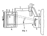
- FIG. 1 shows an X-ray examination apparatus 1, in which the X-ray tube 2 is held on a tube-image-layer carrier holder 5 which is height-adjustable on a stand column 3 and rotatable about a horizontal axis 4.
- a radiation diaphragm 6 is flanged onto the X-ray tube 2.
- a cassette holder 7 is attached as an image support at a constant distance from and aligned with the X-ray tube.
- the cassette holder 7 has an insertion slot 8, through which X-ray film cassettes (not shown) can be inserted.
- the clamping means of the cassette holder of which only the setting button 9 is shown, only permit the holding of four different formats 10, 11, 12, 13. These are painted on the side 14 of the cassette holder facing the x-ray tube 2.
- a circular diaphragm disk 16 looks out from the side of the housing 15 of the radiation diaphragm 6. The protruding edge of the diaphragm disk 16 bears the same color 17 as the format limitation 12 painted on the side of the cassette holder facing the x-ray tube, to which the beam cone 18 faded in by the radiation diaphragm 6 is set.
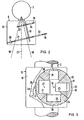
- FIG. 3 shows a catch 28 built into the cover housing 16 and clearly shown in FIG. 3.
- the catch 28 can be brought into engagement in notches 29, 30, 31, 32 made on the circumference of the large diaphragm disk 16. These notches are arranged in such a way that the catch 28 engaging in a notch holds the diaphragm disk 16 in the position in which one of its openings 21, 23, 25, 26 is centered on the central beam 27 of the beam cone which can be suppressed. 3 also shows that the edge of the large diaphragm disk 16 has as many differently colored sections 33, 34, 35, 36 distributed over its circumference as there are openings 21, 23, 25, 26. The colored sections are positioned in such a way that the color assigned to this format appears on the edge of the diaphragm disk 16 protruding from the diaphragm housing 15 for each snap-in masking format.
- the doctor selects an X-ray film cassette that is adapted to the examination area. He can only choose between the four formats 10, 11, 12, 13 drawn on the side of the cassette holder facing the X-ray tube. If he uses an X-ray film cassette of one of these formats, the clamping means holding the X-ray film cassette of this format only when the setting knob 9 is set accordingly on the cassette holder 7, this color can be read off the setting knob in a manner not shown here. It also corresponds to the color with which this format is recorded on the side of the cassette holder 7 facing the X-ray tube 2.
- the operator only needs to rotate the diaphragm disk 16 until this same color appears on the edge of the large diaphragm disk 16 protruding from the housing 15 of the radiation diaphragm 6. If the catch 28 then engages in the corresponding notch 29, 30, 31, 32 at the edge of the diaphragm disk 16, this format is exactly masked out by the radiation diaphragm 6. The recording can be triggered.
- the housing 15 of the radiation diaphragm 6 can be kept smaller, because for the small diaphragm disk 20 facing the X-ray tube 2, the distance from the axis 19 to the central beam 27 becomes smaller and therefore this diaphragm disk can be even smaller than if the axis were aligned parallel to the central beam.
- 20 more space is saved by the inclination of the axis 19 due to the diagonal setting of this smaller diaphragm disk. Since the radiation diaphragm 6 does not contain a separate drive and, apart from the axis 19 with the diaphragm disks 16, 20 fixed immovably thereon, contains no moving parts, disturbances are not to be expected.
- a sheet film changer or an X-ray target device could also be used.
Landscapes
- Physics & Mathematics (AREA)
- General Physics & Mathematics (AREA)
- Apparatus For Radiation Diagnosis (AREA)
- Radiography Using Non-Light Waves (AREA)
Applications Claiming Priority (2)
| Application Number | Priority Date | Filing Date | Title |
|---|---|---|---|
| DE3124437 | 1981-06-22 | ||
| DE19813124437 DE3124437A1 (de) | 1981-06-22 | 1981-06-22 | Roentgenuntersuchungsgeraet |
Publications (2)
| Publication Number | Publication Date |
|---|---|
| EP0068202A1 EP0068202A1 (de) | 1983-01-05 |
| EP0068202B1 true EP0068202B1 (de) | 1984-09-12 |
Family
ID=6135088
Family Applications (1)
| Application Number | Title | Priority Date | Filing Date |
|---|---|---|---|
| EP82105040A Expired EP0068202B1 (de) | 1981-06-22 | 1982-06-08 | Röntgenuntersuchungsgerät |
Country Status (7)
| Country | Link |
|---|---|
| EP (1) | EP0068202B1 (OSRAM) |
| JP (2) | JPS584133A (OSRAM) |
| DE (2) | DE3124437A1 (OSRAM) |
| DK (1) | DK152406C (OSRAM) |
| ES (1) | ES8304790A1 (OSRAM) |
| FI (1) | FI68357C (OSRAM) |
| IN (1) | IN154602B (OSRAM) |
Families Citing this family (3)
| Publication number | Priority date | Publication date | Assignee | Title |
|---|---|---|---|---|
| DE8436281U1 (de) * | 1984-12-11 | 1986-04-10 | Siemens AG, 1000 Berlin und 8000 München | Primärstrahlenblende für Röntgenuntersuchungsgeräte |
| JPH0715524Y2 (ja) * | 1988-09-13 | 1995-04-12 | 株式会社モリタ製作所 | 歯科用パノラマ・セファロx線撮影装置 |
| US20130266578A1 (en) | 2010-04-07 | 2013-10-10 | Thomas E. Hughes | Methods of treating an overweight subject |
Family Cites Families (9)
| Publication number | Priority date | Publication date | Assignee | Title |
|---|---|---|---|---|
| DE1061177B (de) * | 1958-02-28 | 1959-07-09 | Siemens Reiniger Werke Ag | Roentgenuntersuchungsgeraet mit selbsttaetig verstellbarer Primaerstrahlenblende |
| DE1192513B (de) * | 1963-05-11 | 1965-05-06 | Siemens Reiniger Werke Ag | Einrichtung zur Anfertigung gezielter Roentgen-aufnahmen |
| DE1229380B (de) * | 1964-03-28 | 1966-11-24 | Siemens Reiniger Werke Ag | Roentgenzielgeraet |
| US3502878A (en) * | 1967-09-22 | 1970-03-24 | Us Health Education & Welfare | Automatic x-ray apparatus for limiting the field size of a projected x-ray beam in response to film size and to source-to-film distance |
| US3518435A (en) * | 1967-11-24 | 1970-06-30 | Philips Corp | Automatic x-radiation collimating apparatus responsive to film cassette size |
| US3643095A (en) * | 1969-11-28 | 1972-02-15 | Picker Corp | Automatic collimator control for x-ray apparatus |
| US3764808A (en) * | 1971-11-26 | 1973-10-09 | Sybron Corp | Apparatus for automatically limiting the size of an x-ray beam in response to cassette size |
| JPS5427388A (en) * | 1977-08-01 | 1979-03-01 | Morita Mfg | Dental maxillary xxray camera |
| JPS5489596A (en) * | 1977-12-27 | 1979-07-16 | Nec Corp | Swing and iris set for x-rays |
-
1981
- 1981-06-22 DE DE19813124437 patent/DE3124437A1/de not_active Withdrawn
-
1982
- 1982-05-06 IN IN510/CAL/82A patent/IN154602B/en unknown
- 1982-06-07 FI FI822019A patent/FI68357C/fi not_active IP Right Cessation
- 1982-06-08 EP EP82105040A patent/EP0068202B1/de not_active Expired
- 1982-06-08 DE DE8282105040T patent/DE3260722D1/de not_active Expired
- 1982-06-18 JP JP57105260A patent/JPS584133A/ja active Pending
- 1982-06-21 DK DK276982A patent/DK152406C/da not_active IP Right Cessation
- 1982-06-21 ES ES513305A patent/ES8304790A1/es not_active Expired
-
1983
- 1983-09-14 JP JP1983143237U patent/JPS5989350U/ja active Pending
Also Published As
| Publication number | Publication date |
|---|---|
| FI822019L (fi) | 1982-12-23 |
| JPS584133A (ja) | 1983-01-11 |
| IN154602B (OSRAM) | 1984-11-17 |
| JPS5989350U (ja) | 1984-06-16 |
| DE3124437A1 (de) | 1982-12-30 |
| DK276982A (da) | 1982-12-23 |
| ES513305A0 (es) | 1983-03-16 |
| DE3260722D1 (en) | 1984-10-18 |
| FI68357C (fi) | 1985-09-10 |
| DK152406C (da) | 1988-08-08 |
| FI68357B (fi) | 1985-05-31 |
| FI822019A0 (fi) | 1982-06-07 |
| EP0068202A1 (de) | 1983-01-05 |
| DK152406B (da) | 1988-02-29 |
| ES8304790A1 (es) | 1983-03-16 |
Similar Documents
| Publication | Publication Date | Title |
|---|---|---|
| DE2027180C3 (de) | Einrichtung zum Abfragen einer Person und Aufnahme und Verarbeitung ihrer Antworten | |
| DE3928282A1 (de) | Roentgenaufnahmevorrichtung | |
| EP0156988B1 (de) | Röntgendiagnostikgerät | |
| DE2946078C2 (de) | Vorrichtung zum Projizieren eines Kennzeichenbildes auf einen Film | |
| EP0068202B1 (de) | Röntgenuntersuchungsgerät | |
| EP0133488A1 (de) | Computertomograph | |
| EP0184695B1 (de) | Primärstrahlenblende für Röntgenuntersuchungsgeräte | |
| EP0052327B1 (de) | Vorrichtung zum Projizieren eines Kennzeichenbildes auf einen Film | |
| DE8118153U1 (de) | Röntgenuntersuchungsgerät | |
| DE2721480C3 (de) | Daten-Lichtdruckvorrichtung für eine Kamera | |
| DE3246114A1 (de) | Roentgenuntersuchungsgeraet mit einer primaerstrahlenblende | |
| EP0121151B1 (de) | Röntgendiagnostikgerät | |
| DE2831399C2 (de) | Durchleuchtungsgerät mit einer Weichstrahlröntgenröhre, einer einem Bildverstärker vorgeschalteten Leuchtstoffschicht und einer Fernsehkamera | |
| DE2632799A1 (de) | Echolotschreiber | |
| DE2152647C3 (de) | Szintillationskamera zum Aufnehmen der Verteilung von Radioisotopen in einem Objekt | |
| DE2831513C2 (de) | Kontrollgerät für Röntgenapparate | |
| DE8435384U1 (de) | Primärstrahlenblende für Röntgenuntersuchungsgeräte | |
| DE2428441C3 (de) | Einrichtung zur perimetrischen Prüfung des Gesichtsfeldes eines menschlichen Auges | |
| DE1772408C3 (de) | Optisches Aufnahme- und Wiedergabegerät | |
| DE2407857B2 (de) | Röntgeneinrichtung mit Voreinstelleinheiten zur Voreinstellung von Aufnahmedaten-Kombinationen für verschiedene Organe sowie mit Abruf tasten zur Einstellung jeweils einer der Aufnahmedaten-Kombinationen | |
| DE2056666A1 (de) | Projektionsgerät fur Mehrfachsektoren diapositive | |
| DE1272015B (de) | Projektionswaage | |
| DE955650C (de) | Roentgenuntersuchungseinrichtung mit einem Bildverstaerker und einer Kinokamera | |
| DE1801540C (de) | Vorrichtung zur getrennten Wiederga be von bildmaßigen Aufzeichnungen | |
| DE974294C (de) | Einrichtung zur Herstellung von Roentgenserienaufnahmen in zwei winklig, vorzugsweise rechtwinklig, zueinanderliegenden Ebenen |
Legal Events
| Date | Code | Title | Description |
|---|---|---|---|
| PUAI | Public reference made under article 153(3) epc to a published international application that has entered the european phase |
Free format text: ORIGINAL CODE: 0009012 |
|
| AK | Designated contracting states |
Designated state(s): BE CH DE FR GB IT LI SE |
|
| 17P | Request for examination filed |
Effective date: 19830124 |
|
| ITF | It: translation for a ep patent filed | ||
| GRAA | (expected) grant |
Free format text: ORIGINAL CODE: 0009210 |
|
| AK | Designated contracting states |
Designated state(s): BE CH DE FR GB IT LI SE |
|
| PG25 | Lapsed in a contracting state [announced via postgrant information from national office to epo] |
Ref country code: SE Effective date: 19840912 |
|
| REF | Corresponds to: |
Ref document number: 3260722 Country of ref document: DE Date of ref document: 19841018 |
|
| ET | Fr: translation filed | ||
| PLBE | No opposition filed within time limit |
Free format text: ORIGINAL CODE: 0009261 |
|
| STAA | Information on the status of an ep patent application or granted ep patent |
Free format text: STATUS: NO OPPOSITION FILED WITHIN TIME LIMIT |
|
| 26N | No opposition filed | ||
| PG25 | Lapsed in a contracting state [announced via postgrant information from national office to epo] |
Ref country code: GB Effective date: 19890608 |
|
| PG25 | Lapsed in a contracting state [announced via postgrant information from national office to epo] |
Ref country code: LI Effective date: 19890630 Ref country code: CH Effective date: 19890630 Ref country code: BE Effective date: 19890630 |
|
| BERE | Be: lapsed |
Owner name: SIEMENS A.G. BERLIN UND MUNCHEN Effective date: 19890630 |
|
| GBPC | Gb: european patent ceased through non-payment of renewal fee | ||
| PG25 | Lapsed in a contracting state [announced via postgrant information from national office to epo] |
Ref country code: FR Free format text: LAPSE BECAUSE OF NON-PAYMENT OF DUE FEES Effective date: 19900228 |
|
| REG | Reference to a national code |
Ref country code: CH Ref legal event code: PL |
|
| PG25 | Lapsed in a contracting state [announced via postgrant information from national office to epo] |
Ref country code: DE Effective date: 19900301 |
|
| REG | Reference to a national code |
Ref country code: FR Ref legal event code: ST |