EP0063820B1 - Cleaner using water jets under pressure - Google Patents
Cleaner using water jets under pressure Download PDFInfo
- Publication number
- EP0063820B1 EP0063820B1 EP82103587A EP82103587A EP0063820B1 EP 0063820 B1 EP0063820 B1 EP 0063820B1 EP 82103587 A EP82103587 A EP 82103587A EP 82103587 A EP82103587 A EP 82103587A EP 0063820 B1 EP0063820 B1 EP 0063820B1
- Authority
- EP
- European Patent Office
- Prior art keywords
- water
- cleaning head
- outlet pipes
- jet pressure
- cleaner
- Prior art date
- Legal status (The legal status is an assumption and is not a legal conclusion. Google has not performed a legal analysis and makes no representation as to the accuracy of the status listed.)
- Expired
Links
Images

Classifications
-
- E—FIXED CONSTRUCTIONS
- E03—WATER SUPPLY; SEWERAGE
- E03C—DOMESTIC PLUMBING INSTALLATIONS FOR FRESH WATER OR WASTE WATER; SINKS
- E03C1/00—Domestic plumbing installations for fresh water or waste water; Sinks
- E03C1/12—Plumbing installations for waste water; Basins or fountains connected thereto; Sinks
- E03C1/30—Devices to facilitate removing of obstructions in waste-pipes or sinks
- E03C1/304—Devices to facilitate removing of obstructions in waste-pipes or sinks using fluid under pressure
- E03C1/306—Devices to facilitate removing of obstructions in waste-pipes or sinks using fluid under pressure by means of a tube connected to the water mains
Definitions
- the invention relates to a water pressure jet cleaner according to the preamble of claim 1.
- Such a water pressure jet cleaner has become known, for example, from US Pat. No. 3,937,404, which comprises a hose which can be connected to a water tap and which can be introduced into a spout or siphon.
- this pressure jet cleaner comprises an elastic member through which the water hose is guided axially.
- a cleaner head with several outlet openings on the side, through which the pressurized water enters at an angle to the head
- This water pressure jet cleaner has several disadvantages. As can be seen from the aforementioned US-PS, the outer circumference of the cleaning head is only insignificantly smaller than the inlet opening of the spout. It is therefore not possible to use this cleaning head in almost all applications, since the spouts are usually provided with spout screens. These generally have, for example, an axis cross or several small circular and centrally arranged round outlet openings. In all these cases, where the spout has any kind of spout sieves, this previously known cleaning head cannot be used.
- a device for cleaning kitchen sinks has also become known from DE-C 89 519, a rigid tube with a lower outlet opening being used here.
- the use with pouring sieves is also not possible for the same reasons because of the large diameter of the water outlet pipe.
- vertical adjustment by the screw-in tube can only be achieved in small dimensions.
- the water pressure jet cleaner according to the invention can also be used for drains which contain a drain strainer.
- this generally applies to all drain screens that have become known since they comprise at least several circular openings.
- the cleaning head itself is arranged above the pouring sieve with the sealing piece and does not itself have to be inserted under the pouring sieve.
- the partial elasticity of the water outlet pipes is guaranteed.
- the water outlet pipes can be bent within certain limits and guided through the pouring sieve. Above all, no uncontrolled recoil movement is generated, since the partial elasticity still ensures that the outlet ends of the water outlet pipes are firmly inserted into the sump. Ultimately, the slanted outlet openings make it easier to insert the ends of the water outlet pipes into the sump in the siphon.
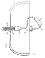
- a water pressure jet cleaner 1 is shown in use in a sink 3 with a spout 5, in which a blockage is to be solved.
- the water pressure jet cleaner 1 is connected with its connecting piece 7 to a tap 9.
- a plurality of 6 water outlet pipes 15 protrude from the cleaning head 13, which are shown in the exemplary embodiment shown, and are correspondingly introduced into the spout 5. Since the water outlet pipes 15 are elastic or at least partially elastic, which means that the radius can be changed by lateral displacement, these can be passed through any pouring sieves, so that the drain sieve can thereby be bridged.
- the partially elastic water outlet pipes are each bent outwards or slightly inwards, which means that they are adapted to a continuous sieve.
- the number, the length and the diameter of the water outlet pipes 15 can vary as required. A common diameter can be 6 mm, for example. With this arrangement, the water pressure can act unhindered without reduction in the pouring area.
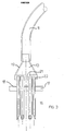
- FIGS. 2a and 3 in which the cleaning head 13 is shown in section.
- the cleaner head 13 consists essentially of a funnel-shaped housing 19, the upper influential end of which is firmly connected to the connecting hose 9.
- the training can be in one piece.
- the connecting hose 9 it is also possible for the connecting hose 9 to be plugged on and for example to be firmly connected with clamps.
- Opposite is a holding block 21 with a plurality of fitting bores 23 through which the water inlet pipes 15 protrude.
- the design can be such that the water outlet pipes 15 can be pushed through these bores in order to vary the length of the water outlet pipes which projects beyond the outside.
- the water outlet pipes 15 are chamfered.
- the partially elastic water outlet pipes 15, for example in the form of plastic tubes, are arranged in a circle, the size of the holding block 21 being for example 36 mm in diameter and 25 mm in height.
- the outlet tube itself can between z. B. 4-20 cm and longer.
- sealing plate 17 is also provided, through which the water outlet pipes 15 also protrude.
- This sealing plate 17 preferably consists of an elastomeric material, for example sealing rubber, in order to thereby seal the back-flowing water from the drain 5.
- the sealing plate 17 can be considerably thicker than in the exemplary embodiment shown.
- an additional base plate 18 can be provided between the cleaner head and the sealing plate, via which the sealing plate 17 can be pressed onto the casting 5. It is also possible, however, that the cleaning head 13 itself is pressed onto the drain 5 together with the sealing plate 17 adjoining it.
- FIGS. 2b and 4-6 in which u. a. the connecting piece 7 is shown.
- This essentially consists of a kind of insulating hose e.g. Insul foam rubber or foam rubber or the like, the consistency of which is essentially rubber foam-like and thus has good elasticity and strength. Therefore, this connecting piece 7 can be pulled onto a wide variety of taps without having to make a different adaptation of the connecting piece to the respective tap.
- the connecting hose 9 can be simply plugged into the connecting piece 7, for example, or can also be additionally fastened with hose clips, not shown in any more detail.
- an outer skin 25 in the form of a rubber tube can also be provided.
- connection piece 7 is fastened to the water tap 9 in the exemplary embodiment according to FIG. 2 b by means of a clamping device which is designed in the form of a clamping collar 27.
Description
Die Erfindung betrifft einen Wasserdruckstrahlreiniger nach dem Oberbegriff des Anspruches 1.The invention relates to a water pressure jet cleaner according to the preamble of
Ein derartiger Wasserdruckstrahlreiniger ist beispielsweise aus der US-A- 3 937 404 bekanntgeworden, der einen an einem Wasserhahn anschließbaren Schlauch umfaßt, der in einen Ausguß bzw. Siphon hineingeführt werden kann.Such a water pressure jet cleaner has become known, for example, from US Pat. No. 3,937,404, which comprises a hose which can be connected to a water tap and which can be introduced into a spout or siphon.
Zur Abdichtung umfaßt dieser Druckstrahlreiniger ein elastisches Glied, durch das hindurch der Wasserschlauch axial verschiebbar geführt ist. Am unteren Ende ist ein Reinigerkopf mit mehreren seitlich angebrachten Austrittsöffnungen angeordnet, über die das eingeführte Druckwasser schräg zum Reinigerkopf austritt,To seal this pressure jet cleaner comprises an elastic member through which the water hose is guided axially. At the lower end there is a cleaner head with several outlet openings on the side, through which the pressurized water enters at an angle to the head
Dieser Wasserdruckstrahlreiniger weist aber mehrere Nachteile auf. Wie nämlich aus der genannten US-PS ersichtlich ist, ist der Außenumfang des Reinigerkopfes nur unwesentlich geringer als die Einführöffnung des Ausgusses. Von daher ist ein Einsatz dieses Reinigerkopfes in fast allen Anwendungsfällen nicht möglich, da in der Regel die Ausgüsse mit Ausgußsieben versehen sind. Diese weisen beispielsweise in der Regel ein Achsenkreuz oder mehrere kleine kreisförmig und zentral angeordnete runde Austrittsöffnungen auf. In all diesen Fällen, wo also der Ausguß irgendwie geartete Ausgußsiebe aufweist, ist dieser vorbekannte Reinigerkopf nicht einsetzbar.This water pressure jet cleaner has several disadvantages. As can be seen from the aforementioned US-PS, the outer circumference of the cleaning head is only insignificantly smaller than the inlet opening of the spout. It is therefore not possible to use this cleaning head in almost all applications, since the spouts are usually provided with spout screens. These generally have, for example, an axis cross or several small circular and centrally arranged round outlet openings. In all these cases, where the spout has any kind of spout sieves, this previously known cleaning head cannot be used.
Aber auch bei den verbleibenden Fällen, wo ein Ausguß vielleicht nicht mit einem Ausgußsieb versehen ist, läßt sich mit diesem der gewünschte Reinigungseffekt nicht im ausreichenden Maße erzielen. In der Regel nämlich ergeben sich Verstopfungen in einem Ausguß dadurch, daß sich insbesondere abkühlendes Fett an den Wandungen absetzt und Schwebstoffe sich daran anlagern. Dieser Prozeß hält an, bis die zum Teil auch noch absinkenden Schwebstoffe zusätzlich vom Boden her langsam die Bogenöffnung eines Siphons verschließen. Bei der im absteigenden Siphonrohr sich zunächst noch mit niedriger Dichte ausbildenden Sumpfschicht setzen sich weitere Teilchen, Schwebstoffe und Fett ab, bis die Ablagerungen so dicht werden, daß das Wasser überhaupt nicht mehr abzulaufen vermag. Führt man den vorbekannten Reinigerkopf in das absteigende Siphonrohr bis zur Verstopfung ein, so kann dieser in die Sumpfschicht selbst aufgrund seiner großförmigen Ausbildung nicht eindringen. Ferner entsteht sogar beim Öffnen des Wasserhahnes und, sofern der Abdichtpfropfen am Ausguß leicht gelockert wird, so daß das über den Reinigerkopf ausgeströmte Wasser bis in das Becken aufsteigt, ein nicht unbeachtlicher Rückstoßeffekt, der den Reinigerkopf aufgrund des elastischen Schlauches von der Verstopfung weg nach oben führt. Ähnlich wie bei einem Gartenschlauch, den man weit von seinem Ende hält, führt also das Schlauchende unkontrollierte Bewegungen aus.But even in the remaining cases, where a spout may not be provided with a spout screen, the desired cleaning effect cannot be achieved to a sufficient extent. As a rule, blockages in a spout result from the fact that cooling grease in particular settles on the walls and suspended matter accumulates on it. This process continues until the suspended particles, some of which also sink, also slowly close the arch opening of a siphon from the bottom. In the bottom layer, which initially forms with a low density in the descending siphon tube, further particles, suspended matter and fat settle until the deposits become so dense that the water is no longer able to run off. If the known cleaning head is inserted into the descending siphon pipe until it becomes blocked, it cannot penetrate into the sump layer itself due to its large size. Furthermore, even when the tap is opened and if the sealing plug on the spout is loosened slightly so that the water flowing out through the cleaning head rises up into the basin, a not inconsiderable recoil effect occurs, which, due to the elastic hose, removes the cleaning head from the blockage leads. Similar to a garden hose that is held far from its end, the end of the hose carries out uncontrolled movements.
Eine Vorrichtung zum Reinigen von Küchenausgüssen ist auch aus der DE-C 89 519 bekanntgeworden, wobei hier ein starres Rohr mit einer unteren Austrittsöffnung verwendet wird. Der Einsatz bei Ausgußsieben ist aber auch hier aus den gleichen Gründen wegen des großen Durchmessers des Wasseraustrittsrohres nicht möglich. Zudem ist eine Vertikalverstellung durch das einschraubbare Rohr nur in geringen Abmessungen verwirklichbar.A device for cleaning kitchen sinks has also become known from DE-C 89 519, a rigid tube with a lower outlet opening being used here. The use with pouring sieves is also not possible for the same reasons because of the large diameter of the water outlet pipe. In addition, vertical adjustment by the screw-in tube can only be achieved in small dimensions.
Demgegenüber ist es Aufgabe der vorliegenden Erfindung, einen Wasserdruckstrahlreiniger zu schaffen, mit dem auf einfachste Weise bei leichter Handhabung schnell verstopfte, auch gegebenenfalls mit einem Abflußsieb versehene Ausgüsse von der Verstopfung befreit werden können. Die Aufgabe wird erfindungsgemäß entsprechend den im kennzeichnenden Teil des Anspruches 1 angegebenen Merkmalen gelöst. Vorteilhafte Ausgestaltungen der Erfindung sind in den Unteransprüchen angegeben.In contrast, it is an object of the present invention to provide a water pressure jet cleaner which can be used to remove blockages quickly and easily in the simplest manner, with easy handling, and possibly with a drain strainer. The object is achieved according to the features specified in the characterizing part of
Durch die vorliegende Erfindung wird ein wesentlicher technischer Fortschritt erzielt. Vor allem läßt sich der erfindungsgemäße Wasserdruckstrahlreiniger auch bei Abflüssen verwenden, die ein Abflußsieb enthalten. Dies gilt praktisch in der Regel für alle bisher bekanntgewordenen Abflußsiebe, da diese zumindest mehrere kreisförmige Öffnungen umfassen. Dazu ist aber eben ferner notwendig, daß der Reinigerkopf selbst oberhalb des Ausgußsiebes mit dem Abdichtstück angeordnet wird und selbst nicht bis unter das Ausgußsieb hineingeführt werden muß.A significant technical advance is achieved by the present invention. Above all, the water pressure jet cleaner according to the invention can also be used for drains which contain a drain strainer. In practice, this generally applies to all drain screens that have become known since they comprise at least several circular openings. For this purpose, however, it is also necessary that the cleaning head itself is arranged above the pouring sieve with the sealing piece and does not itself have to be inserted under the pouring sieve.
Durch die in weiten Grenzen gewährleistete axiale Höhenverstellung der Wasseraustrittsrohre und deren relativ geringen Durchmesser wird ferner gewährleistet, daß diese bis in den die Verstopfung bewirkenden Sumpf hineingesteckt werden können. Dadurch läßt sich eine optimale Aufwirbelung vor allem der oberen Schichten der Verstopfungen gewährleisten.The axial height adjustment of the water outlet pipes and their relatively small diameter, which is ensured within wide limits, also ensures that these can be inserted into the sump causing the blockage. This ensures optimal swirling, especially of the upper layers of the blockages.
Ein weiterer Vorteil wird durch die Teilelastizität der Wasseraustrittsrohre gewährleistet. Entsprechend den Formen der Ausgußsiebe können dabei die Wasseraustrittsrohre in gewissen Grenzen verbogen und durch das Ausgußsieb hindurch geführt werden. Vor allem wird keine unkontrollierte Rückstoßbewegung erzeugt, da durch die Teilelastizität das feste Einstecken der Austrittsenden der Wasseraustrittsrohre in den Sumpf immer noch gewährleistet wird. Letztendlich wird das Einstecken der Enden der Wasseraustrittsrohre in den Sumpf im Siphon durch die abgeschrägten Austrittsöffnungen noch erleichtert.Another advantage is guaranteed by the partial elasticity of the water outlet pipes. Depending on the shape of the pouring sieves, the water outlet pipes can be bent within certain limits and guided through the pouring sieve. Above all, no uncontrolled recoil movement is generated, since the partial elasticity still ensures that the outlet ends of the water outlet pipes are firmly inserted into the sump. Ultimately, the slanted outlet openings make it easier to insert the ends of the water outlet pipes into the sump in the siphon.
Weiter Einzelheiten, Vorteile und Merkmale der Erfindung ergeben sich nachfolgend aus den an Hand von Zeichnungen dargestellten Ausführungsbeispielen. Dabei zeigen im einzelnen
- Figur 1: Eine schematische Ansicht des Wasserdruckstrahlreinigers im Einsatz in einem Waschbecken;
- Figur 2a und 2b: eine perspektivische Ansicht des Reinigungskopfes und des Anschlußstückes;
- Figur 3: eine Schnittansicht des Reinigungskopfes.
- Figure 1: A schematic view of the water pressure jet cleaner in use in a sink;
- Figures 2a and 2b: a perspective view the cleaning head and the connector;
- Figure 3: a sectional view of the cleaning head.
In Fig. 1 ist ein Wasserdruckstrahlreiniger 1 im Einsatz in einem Waschbecken 3 mit einem Ausguß 5 gezeigt, in dem eine Verstopfung gelöst werden soll. Der Wasserdruckstrahlreiniger 1 wird dabei mit seinem Anschlußstutzen 7 an einem Wasserhahn 9 angeschlossen. Aus dem Reinigerkopf 13 ragen mehrere, im gezeigten Ausführungsbeispiel 6 Wasseraustrittsrohre 15, die in den Ausguß 5 entsprechend eingeführt werden. Da die Wasseraustrittsrohre 15 elastisch oder zumindestteilweise elastisch sind, womit durch seitliches Versetzen der Radius verändert werden kann, können diese durch beliebig ausgebildete Ausgußsiebe hindurch geführt werden, sodaß sich hierdurch das Ablaufsieb überbrücken läßt. Dabei werden die teilelastischen Wasseraustrittsrohre jeweils nach außen oder leicht nach innen gebogen, wodurch die jeweilige Anpassung an ein Durchlaufsieb erfolgt. Die Zahl, die Länge und der Durchmesser der Wasseraustrittsrohre 15 kann je nach Bedarf variieren. Ein gebräuchlicher Durchmesser kann beispielsweise bei 6 mm liegen. Durch diese Anordnung kann der Wasserdruck ungehindert ohne Minderung in dem Ausgußbereich einwirken.In Fig. 1, a water
Im folgenden wird auf die Fig. 2a und 3 bezug genommen, in der der Reinigerkopf 13 im Schnitt gezeigt ist.In the following, reference is made to FIGS. 2a and 3, in which the
Der Reinigerkopf 13 besteht dabei im wesentlichen aus einem trichterförmigen Gehäuse 19, dessen oberes Einflußende mit dem Verbindungsschlauch 9 festverbunden ist. Die Ausbildung kann einstückig sein. Möglich ist aber auch, daß der Verbindungsschlauch 9 aufgesteckt wird und beispielsweise mit Klemmen festverbunden wird. Gegenüberliegend ist ein Halteblock 21 mit mehreren Paßbohrungen 23 angeordnet, durch die die Wassereintrittsrohre 15 hindurchragen. Dabei kann die Ausbildung derart sein, daß die Wasseraustrittsrohre 15 durch diese Bohrungen hindurchgeschoben werden können, um die außen überstehende Länge der Wasseraustrittsrohre zu variieren. Am unteren Ende sind die Wasseraustrittsrohre 15 angeschrägt. Die Anordnung der teilelastischen Wasseraustrittsrohre 15 beispielsweise in Form von Kunststoffröhrchen erfolgt kreisförmig, wobei die Größe des Halteblockes 21 beispielsweise einen Durchmesser von 36 mm und 25 mm Höhe aufweisen kann. Die Austrittsröhrchen selbst können zwischen z. B. 4-20 cm und länger sein.The
Zusätzlich ist noch die Dichtplatte 17 vorgesehen, durch die die Wasseraustrittsrohre 15 ebenfalls hindurchragen. Diese Dichtplatte 17 besteht vorzugsweise aus einem elastomeren Werkstoff, beispielsweise Abdichtgummi, um hierdurch das rückströmende Wasser aus dem Abfluß 5 abzudichten. Die Dichtplatte 17 kann dabei erheblich dicker sein als in dem gezeigten Ausführungsbeispiol.In addition, the
Zusätzlich kann zwischen dem Reinigerkopf und der Dichtplatte noch eine zusätzliche Unterlagsplatte 18 vorgesehen sein, über die die Dichtplatte 17 auf den Abguß 5 gedrückt werden kann. Möglich ist aber auch, daß der Reinigerkopf 13 selbst gemeinsam mit der daran angrenzenden Dichtplatte 17 auf den Abfluß 5 gedrückt wird.In addition, an
Im folgenden wird auf die Figuren 2b und 4-6 bezug genommen, in denen u. a. der Anscblußstutzen 7 gezeigt ist. Dieser besteht im wesentlichen aus einem Art Isolierschlauch z.B. Insul Schaumgummi oder Moosgummi o. Ä., dessen Konsistenz im wesentlichen gummischaumartig ist und somit eine gute Elastizität und Festigkeit aufweist. Von daher läßt sich dieser Anschlußstutzon 7 auf die verschiedensten Wasserhähne aufziehen, ohne daß eine unterschiedliche Anpassung der Anschlußstutzen an den jeweiligen Wasserhahn vorgenommen werden muß. Der Verbindungsschlauch 9 kann dabei an dem Anschlußstutzen 7 beispielsweise einfach eingesteckt werden oder aber auch noch zusätzlich mit nicht näher gezeigten Schlauchklemmen befestigt werden. Um die Festigkeit der gesamten Anordnung zu erhöhen, kann zusätzlich noch eine Außenhaut 25 in Form eines aufgezogenen Gummischlauches vorgesehen sein.In the following, reference is made to FIGS. 2b and 4-6, in which u. a. the connecting
Die Befestigung des Anschlußstutzens 7 an dem Wasserhahn 9 erfolgt in dem Ausführungsbeispiel nach Fig. 2b mittels einer Klemmeinrichtung, die in Form einer Klemmanschette 27 ausgebildet ist.The
An beiden Enden der Klemmanscbette 27 sind dabei nur schematisch gezeigte Abwinkelungen 29a und 29b vorgesehen, durch die eine Schraube 31 greift. Da in der Abwinkelung 29b ein innenliegendes Gewinde eingebracht ist, wird beim Drehen der Schraube 31 die Manschette entsprechend zusammengezogen oder auseinandergedrückt, sodaß dadurch eine dichte Befestigung des Anschlußstutzens am Wasserhahn erfolgen kann.At both ends of the clamping
Claims (7)
Applications Claiming Priority (2)
| Application Number | Priority Date | Filing Date | Title |
|---|---|---|---|
| DE19818112559U DE8112559U1 (en) | 1981-04-28 | 1981-04-28 | WATER PRESSURE JET CLEANER FROM BLOCKED DRAIN IN WASHBASIN, SINK, BATHTUBS, SHOWERS, OUTLETS ETC. UTILIZING THE PRESSURE IN THE WATER PIPING SYSTEM THROUGH A DIRECT CONNECTION BETWEEN WATER DRAIN TAP AND DRAIN SYSTEM |
| DE8112559U | 1981-04-28 |
Publications (3)
| Publication Number | Publication Date |
|---|---|
| EP0063820A2 EP0063820A2 (en) | 1982-11-03 |
| EP0063820A3 EP0063820A3 (en) | 1983-02-02 |
| EP0063820B1 true EP0063820B1 (en) | 1986-08-13 |
Family
ID=6727169
Family Applications (1)
| Application Number | Title | Priority Date | Filing Date |
|---|---|---|---|
| EP82103587A Expired EP0063820B1 (en) | 1981-04-28 | 1982-04-27 | Cleaner using water jets under pressure |
Country Status (2)
| Country | Link |
|---|---|
| EP (1) | EP0063820B1 (en) |
| DE (2) | DE8112559U1 (en) |
Families Citing this family (1)
| Publication number | Priority date | Publication date | Assignee | Title |
|---|---|---|---|---|
| GB2200709A (en) * | 1987-02-10 | 1988-08-10 | Alan Thompson | Device for clearing a waste trap |
Citations (1)
| Publication number | Priority date | Publication date | Assignee | Title |
|---|---|---|---|---|
| GB855797A (en) * | 1957-02-27 | 1960-12-07 | Reiss Engineering Company Ltd | Improvements in or relating to liquid spray arrangements |
Family Cites Families (9)
| Publication number | Priority date | Publication date | Assignee | Title |
|---|---|---|---|---|
| DE89519C (en) * | ||||
| CH146338A (en) * | 1930-03-15 | 1931-04-15 | Sternegger Mathias | Hose fastening collar. |
| DE806817C (en) * | 1949-01-18 | 1951-06-18 | Alexander Reineck | Threadless pipe quick coupling |
| FR1092792A (en) * | 1954-02-05 | 1955-04-27 | Automatic connection | |
| GB792136A (en) * | 1955-10-12 | 1958-03-19 | George James Webbing Lambert | Improvements in joints and couplings for uniting two elements such as pipes |
| ZA721758B (en) * | 1972-03-14 | 1973-08-29 | R Onesta | A device to facilitate the clearing of a blocked drain |
| DE2444571A1 (en) * | 1974-09-18 | 1976-04-01 | Horst Bruns | Drain unblocking device for baths and sinks - uses water jet from supply tap directed by hose and resilient cup |
| DE2456678A1 (en) * | 1974-11-30 | 1976-08-12 | Oskar Biegel | Hose coupling for tap with external nozzle thread - has clamp ring with internal tapered contraction flange |
| US3937404A (en) * | 1975-06-09 | 1976-02-10 | Johnson Arthur L | Drain declogging device |
-
1981
- 1981-04-28 DE DE19818112559U patent/DE8112559U1/en not_active Expired
-
1982
- 1982-04-27 DE DE8282103587T patent/DE3272531D1/en not_active Expired
- 1982-04-27 EP EP82103587A patent/EP0063820B1/en not_active Expired
Patent Citations (1)
| Publication number | Priority date | Publication date | Assignee | Title |
|---|---|---|---|---|
| GB855797A (en) * | 1957-02-27 | 1960-12-07 | Reiss Engineering Company Ltd | Improvements in or relating to liquid spray arrangements |
Also Published As
| Publication number | Publication date |
|---|---|
| DE3272531D1 (en) | 1986-09-18 |
| EP0063820A2 (en) | 1982-11-03 |
| EP0063820A3 (en) | 1983-02-02 |
| DE8112559U1 (en) | 1982-10-14 |
Similar Documents
| Publication | Publication Date | Title |
|---|---|---|
| EP0787864B1 (en) | Sanitary security device | |
| DE2431516B2 (en) | Device for dispensing fluids | |
| DE3790241C3 (en) | Single-handle faucet | |
| DE3007702A1 (en) | INSPECTION CHAMBER FOR A DRAINAGE SYSTEM | |
| DE8533252U1 (en) | Hand tool for cleaning clogged drains | |
| DE10055785A1 (en) | Aerator for feeding large and small diameter air bubbles into waste water has elastomeric sleeve with slits, through which air emerges, on support with rectangular cross-section, larger sides of rectangle being very much larger than shorter | |
| EP0182327A1 (en) | Device for limiting flow-through by throttling within water fittings | |
| EP0063820B1 (en) | Cleaner using water jets under pressure | |
| DE2216678A1 (en) | CONNECTING PIECE MADE OF ELASTIC PLASTIC | |
| EP0643177B1 (en) | Urinal | |
| EP1693316A1 (en) | Outlet device with a cleaning system | |
| DE69922947T2 (en) | Water inlet for bathtub in the form of a cascade | |
| DE6921769U (en) | OUTLET MOUTH PIECE FOR LOW-SPRAYING FLOWS | |
| EP3199715A2 (en) | Overflow for a basin, in particular rinsing basin | |
| EP0916774A2 (en) | Siphon for an outlet pipe, in particular for the outlet pipe of a wash basin, a bath or the like | |
| CH495524A (en) | Toilet with outlet pipe | |
| EP3647504B1 (en) | Sanitary item arrangement | |
| DE102016120782A1 (en) | Sleeve connection construction for outlet nozzles | |
| DE3606550C2 (en) | ||
| AT2673U1 (en) | TUBULAR ELEMENT FOR CONNECTING THE DRAIN PIPE OF A SANITARY SYSTEM TO A DRAIN MUFFLING OR A WALL CONNECTOR | |
| EP0250877A2 (en) | Device for removing obstructions in waste pipes | |
| DE202020103189U1 (en) | Gun for cleaning ears | |
| DE6930154U (en) | SINGLE-PIECE ELASTIC SLEEVE | |
| DE19737720B4 (en) | Method and device for producing a liquid line with a built-in functional component | |
| DE2536849A1 (en) | EXHAUST BRANCH |
Legal Events
| Date | Code | Title | Description |
|---|---|---|---|
| PUAI | Public reference made under article 153(3) epc to a published international application that has entered the european phase |
Free format text: ORIGINAL CODE: 0009012 |
|
| AK | Designated contracting states |
Designated state(s): BE DE FR GB IT NL |
|
| PUAL | Search report despatched |
Free format text: ORIGINAL CODE: 0009013 |
|
| AK | Designated contracting states |
Designated state(s): BE DE FR GB IT NL |
|
| 17P | Request for examination filed |
Effective date: 19830126 |
|
| GRAA | (expected) grant |
Free format text: ORIGINAL CODE: 0009210 |
|
| AK | Designated contracting states |
Kind code of ref document: B1 Designated state(s): BE DE FR GB IT NL |
|
| REF | Corresponds to: |
Ref document number: 3272531 Country of ref document: DE Date of ref document: 19860918 |
|
| ET | Fr: translation filed | ||
| ITF | It: translation for a ep patent filed |
Owner name: UFFICIO BREVETTI RICCARDI & C. |
|
| PLBE | No opposition filed within time limit |
Free format text: ORIGINAL CODE: 0009261 |
|
| STAA | Information on the status of an ep patent application or granted ep patent |
Free format text: STATUS: NO OPPOSITION FILED WITHIN TIME LIMIT |
|
| 26N | No opposition filed | ||
| ITTA | It: last paid annual fee | ||
| PGFP | Annual fee paid to national office [announced via postgrant information from national office to epo] |
Ref country code: GB Payment date: 19940411 Year of fee payment: 13 |
|
| PGFP | Annual fee paid to national office [announced via postgrant information from national office to epo] |
Ref country code: FR Payment date: 19940418 Year of fee payment: 13 |
|
| PGFP | Annual fee paid to national office [announced via postgrant information from national office to epo] |
Ref country code: NL Payment date: 19940430 Year of fee payment: 13 |
|
| PGFP | Annual fee paid to national office [announced via postgrant information from national office to epo] |
Ref country code: BE Payment date: 19940506 Year of fee payment: 13 |
|
| PG25 | Lapsed in a contracting state [announced via postgrant information from national office to epo] |
Ref country code: GB Effective date: 19950427 |
|
| PG25 | Lapsed in a contracting state [announced via postgrant information from national office to epo] |
Ref country code: BE Effective date: 19950430 |
|
| BERE | Be: lapsed |
Owner name: WALTER KLAUS Effective date: 19950430 |
|
| PG25 | Lapsed in a contracting state [announced via postgrant information from national office to epo] |
Ref country code: NL Effective date: 19951101 |
|
| PG25 | Lapsed in a contracting state [announced via postgrant information from national office to epo] |
Ref country code: FR Effective date: 19951229 |
|
| NLV4 | Nl: lapsed or anulled due to non-payment of the annual fee |
Effective date: 19951101 |
|
| GBPC | Gb: european patent ceased through non-payment of renewal fee |
Effective date: 19950427 |
|
| REG | Reference to a national code |
Ref country code: FR Ref legal event code: ST |
|
| PGFP | Annual fee paid to national office [announced via postgrant information from national office to epo] |
Ref country code: DE Payment date: 19981217 Year of fee payment: 17 |
|
| PG25 | Lapsed in a contracting state [announced via postgrant information from national office to epo] |
Ref country code: DE Free format text: LAPSE BECAUSE OF NON-PAYMENT OF DUE FEES Effective date: 20000201 |