EP0063433A2 - Kraftgetriebenes Werkzeug mit verbesserter Bremsvorrichtung - Google Patents
Kraftgetriebenes Werkzeug mit verbesserter Bremsvorrichtung Download PDFInfo
- Publication number
- EP0063433A2 EP0063433A2 EP82301712A EP82301712A EP0063433A2 EP 0063433 A2 EP0063433 A2 EP 0063433A2 EP 82301712 A EP82301712 A EP 82301712A EP 82301712 A EP82301712 A EP 82301712A EP 0063433 A2 EP0063433 A2 EP 0063433A2
- Authority
- EP
- European Patent Office
- Prior art keywords
- energy storage
- safety lever
- spring
- brake
- storage means
- Prior art date
- Legal status (The legal status is an assumption and is not a legal conclusion. Google has not performed a legal analysis and makes no representation as to the accuracy of the status listed.)
- Granted
Links
Images


Classifications
-
- F—MECHANICAL ENGINEERING; LIGHTING; HEATING; WEAPONS; BLASTING
- F16—ENGINEERING ELEMENTS AND UNITS; GENERAL MEASURES FOR PRODUCING AND MAINTAINING EFFECTIVE FUNCTIONING OF MACHINES OR INSTALLATIONS; THERMAL INSULATION IN GENERAL
- F16D—COUPLINGS FOR TRANSMITTING ROTATION; CLUTCHES; BRAKES
- F16D49/00—Brakes with a braking member co-operating with the periphery of a drum, wheel-rim, or the like
- F16D49/08—Brakes with a braking member co-operating with the periphery of a drum, wheel-rim, or the like shaped as an encircling band extending over approximately 360 degrees
-
- B—PERFORMING OPERATIONS; TRANSPORTING
- B27—WORKING OR PRESERVING WOOD OR SIMILAR MATERIAL; NAILING OR STAPLING MACHINES IN GENERAL
- B27B—SAWS FOR WOOD OR SIMILAR MATERIAL; COMPONENTS OR ACCESSORIES THEREFOR
- B27B17/00—Chain saws; Equipment therefor
- B27B17/08—Drives or gearings; Devices for swivelling or tilting the chain saw
- B27B17/083—Devices for arresting movement of the saw chain
Definitions
- This invention relates to an improved braking device for power tools and is primarily intended to be incorporated in portable chain saws or portable circular saws which may be driven by electric motors or internal combustion engines and comprising drive means for the tool, brake means operable on means transmitting power from the drive means to the tool, first energy storage means for applying said brake means, and safety lever means operable to release said first energy storage means and apply said brake means when said safety lever contacts the hand, wrist or arm of an operator during "kick-back" or like violent movement.
- U.S. Patent 4,121,339 and German Offenlegungsschrift No. 2922573 and U.S. Patent 3,923,170 indicate that the guard member forming the safety lever may itself also form an inertia mass during kick-back to actuate the brake by virtue of the inertia of said guard member being equivalent or proximating to the manual force required to activate the brake when such guard lever strikes against the arm or wrist of the operator.
- German Offenlegungsschrist No. 2621818 discloses a guide bar for the chain which is pivotable in the casing so as to displace a lever which in turn trips a safety lever which is also arranged to contact the hand or wrist of an operator during kick-back to actuate the brake.
- German Offenlegungsschrift No. 2632304 also discloses an arrangement wherein a manually actuable safety lever is operable to disengage a clutch. It is desirable to have a device with sufficient sensitivity of operation which has a guard member having the dual function of being operable by striking against the hand or wrist of the operator and also whose own mass may provide sufficient inertia during a kick-back to activate the brake whilst also permitting normal daily use wherein the guard member may come into contact with objects during handling without unnecessarily activating the brake. To overcome this disadvantage, braking devices have been proposed which act immediately as a consequence of a sharp movement of the portable saw when the chain saw moves sharply in the direction of the operator's body and also when the safety lever does not receive an impact from the hand of the operator.
- U.S. Patent 3,785,465 wherein a safety lever is provided to impact the hand of the operator to cause, by electromechanical means, a locking arm to disengage the drive to a centrifugal clutch and to apply a brake to the clutch drum.
- An electrically operated, acceleration sensitive transmitter is also referred to as being arranged in the chain guide bar to energise an electro-magnet when the guide bar is subjected to kick-back and to similarly stop the chain by applying the brake. No details of the nature of the transmitter are given and it is considered such device, apart from being complicated to manufacture, would not produce the desired sensitivity, reliability and speed of reaction of the safety means, nor could such device be produced in economic manner.
- U.S. Patent 3,937,306 discloses a chain saw having a safety lever with spring means actuable to tighten a band brake to stop the chain upon contact with the operator's arm or wrist and further discloses a resiliently mounted carrying handle or front stirrup adjacent said safety lever and having a projection which with sufficient kick-back action also acts to operate the safety lever.
- This arrangement is not considered readily practical since it is difficult to provide the desired resilience of mounting of the front stirrup which permits such to be used as a supporting handle in daily use and which also may be resiliently deflected to activate the brake in desired manner.
- resilient displacement of the supporting handle or stirrup to the brake activating position may well be dependent upon the operator's manual pressure on said supporting handle in addition to any inertial forces which presupposes the operator has maintained his grip on the device with kick-back which is not necessarily the situation and which does not ensure adequate safety.
- U.S. Patents 3,485,326 and 3,485,327 disclose a chain arresting element slidable on an inclined surface upon a kick-back occurring so as to engage with the chain or with a drive drum and whereon said displaceable members are retained until subject to a kick-back force by magnetic means or by a spring bias.
- U.S. Patent 3,485,327 also discloses a spring biased pawl engageable in cogs on a drum secured to the drive shaft to thereby arrest the chain movement. It is not considered in certain circumstances that these devices will be adequate as regards the speed of operation and effectiveness of stopping and, furthermore, these devices do not also include a safety lever operable by striking against the hand or wrist of the operator.
- Dooley discloses an arrangement having a manually operated safety lever which is operable to disengage a clutch and thus remove driving torque from the cutting chain.
- the guide rail or bar around which the cutting chain is rotated is mounted so as to be displaceable by way of its inertia upon being subject to kick-back action so as to disengage clutch means and thereby remove the driving torque from said cutting chain.
- U.S. Patent 3,974,566 discusses various considerations involved in achieving desired safety control and makes mention of the various prior arrangements.
- U.S. Patent 3,974,566 does not disclose a safety lever acting to apply a brake to the chain upon contact with the hand or wrist of an operator during kick-back, but rather achieves a braking effect by way of an inertia mechanism independent of operator manipulation and operable in response to adverse conditions, such as chain saw kick-back, to trigger the release of stored energy developed by operation of said chain saw.
- the stopping time for the chain should not exceed a predetermined time from the time the operator contacts the safety lever in a kick-back situation to the time the chain stops. However, if the chain is stopped too quickly this can result in excessive stresses. It has been found preferable to provide a brake mechanism which will stop the chain quickly from commencement of the kick-back action, and provision of an inertial system with such capability is an object of the invention. Also, when determining the minimum and maximum force to be applied to a safety lever, the minimum force should be such as to avoid accidental braking during normal use, and the maximum force should avoid breaking the operator's wrist. Further, the distance between the handle and safety lever should preferably be small to ensure timely operation of the brake, and the safety lever should not be displaced too far since it must also serve as a protective guard.
- a feature by which this is achieved is the provision of a second energy storage means releasable by an inertia mass effectively independent of the manually actuable safety lever when in the energized position and prior to actuation, the second energy storage means releasing the first energy storage means and applying the brake mechanism upon occurrence of a kick-back or like violent movement.
- the present invention provides a portable power tool, especially a circular saw or chain saw, comprising a braking device actuated by a safety lever loaded by a first spring forming first energy storage means and maintained in the spring-loaded condition by disengageable retaining means, and a striker or hammer release means spring-loaded in a "cocked" position by a second spring forming second energy storage means and released by movement of a displaceable inertia mass, the striker or hammer release means acting positively on the disengageable retaining means so as to release the spring-loaded safety lever in the event of a kick-back or like violent action.
- the second energy storage means and/or the inertia mass may be located on the main chassis of the power tool or completely or partly on the safety lever.
- the safety lever is preferably hollow or box-like and in such situation at least the inertia mass is preferably located within the safety lever so as to be protected thereby and provide a space saving arrangement.
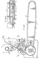
- a blade 10 in a portable chain saw a blade 10 extends in projecting manner from a body 11 provided with an upper grip 12 and a rear grip (not shown).
- the blade 10 comprises a bar 13 on which a saw chain 14 is caused to rotate by a motor- driven sprocket 15.
- a brake drum 16 To the shaft of the sprocket 15 there is keyed a brake drum 16 on which acts a brake including a brake band 17 controlled by a safety device.
- This kind of portable chain saw structure and manually operable brake means is in itself known, and is, for example, similar to that described in the U.S. Patent No. 4,059,895.
- the safety device for controlling the intervention of the brake means utilizing brake band 17 is the subject of the present invention.
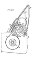
- the safety device is indicated generally by the reference number 18, and comprises a safety lever 19 pivoted at 20 to the body 11, and a flat inertial mass 21 pivoted at 22 in the interior of the box-shaped structure of the lever 19.
- An end of the brake band 17 is secured to a pin 23 of the lever 19, the other end of which is secured at 24 on the body 11.
- the pin 23 is also engageable with a notch 9 of a locking lever 25 pivoted at 26 to the body 11.
- a spring 27 forming a first energy storage means and for the loading of the safety device.
- a tail 28 extends from the lever 25 and cooperates with a trigger 29 forming part of a pawl 30 pivoted in this example to the interior of the box-shaped lever 19 at 31.
- the pawl 30 forms a hammer release means and is provided with a tooth portion 32 which is engageable in a notch 33 of the inertial mass 21 in the cocked position of the device, and is stopped by a further notch 34 in the inertial mass 21.
- the pawl 30 is loaded by means of a compression spring 35 which forms a second energy storage means and acts between it and the safety lever 19, and is maintained in spring-loaded condition by engagement of the tooth portion 32 with the notch 33 of the inertial mass 21.
- the inertial mass 21 is biased towards the trigger 29 by a spring 36 to ensure engagement with the pawl 30 in the cocked position, and such spring 36 may be mounted (not shown) adjustable in force if it is desired to adjust the automatic tripping point.
- pawl 30 and inertial mass 21 be mounted on the lever 19. These components could for example be mounted on the body 11 of the chain saw.
- the re-loading of the safety device takes place by simple manual rotation of the safety lever 19 in an anti- clockwise direction. This causes the tooth 32 to latch onto the notch 33, as a result of the anti-clockwise rotation of the lever 25, thrust by the spring 27, and of the consequent action of its tail 28 on the trigger 29.
- the safety device according to the invention has shown itself to be of highly dependable operation because of the presence of the inertia mass which is independent of the safety lever 19 and which, by means of the unlatching of the pawl 30, releases the entire force of the compression spring 35 so as to cause the safety lever 19 actuating the brake to act positively and instantaneously.
- Another and not negligible advantage of the device in question is its compactness resulting from the box-shaped structure of the safety lever 19 containing and protecting all the mechanisms, to which ready access can be had.
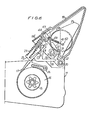
- a modified arrangement is disclosed in Fig. 4 to 7 wherein like or similar parts bear the same reference numerals as in Figs. 1 to 3.
- the main difference in this arrangement comprises replacement of the previous compression spring 35 with a torsional spring 38 which is in tension when loaded and acts against the pawl 30 biassing such towards tail portion 28.
- the weaker acting previous compression spring 36 is replaced by an expansion spring 39 which is a very light spring required to bias the inertia mass 21 in the anti-clockwise direction, as viewed, for recocking the device.
- the torsional spring 38 has one end portion engaged on the safety lever 19 and its other end 40 extends out of the plane of the spring and acts against a shoulder 41 on the pawl 30.
- the expansion spring 39 has a hooked portion at one end engaging in an aperture 42 in inertia mass 21, and a hooked portion 43 at its other end engaging with a detent 44 on the lever 19.
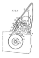
- Fig. 5 the "cocked" position of the safety device is shown whilst in Fig. 6 the released position is shown wherein the device after having undergone kick-back action has, by the unlatching operation of the inertia mass 21 and the subsequent hammer-like striking of the pawl 30 against the tail 28 to release pin 23, moved in the clockwise direction to the position wherein the brake band 17 grips the brake drum 16.
- Fig. 7 the safety device is shown during the recocking movement wherein the safety lever 19 (with mechanism support part 19') is moved anti-clockwise from the position of Fig. 5 to compress load springs 27 and 38, and prior to a slight relaxation whereupon the tooth portion 32 abuts against the notch 33 brought into position under the action of the return spring 39.
- FIG. 8 is a similar view to Fig. 5, and like or similar parts in Fig. 8 bear the same reference numerals as in Fig. 5.
- the safety lever 19, the locking lever 25, the notch 9 and pin 23, and the compression spring 27 all function as previously described.
- the main differences in this embodiment comprise the arrangement, loading and operation of the inertia mass 50, the pawl 52, and the second energy storage means which is in the form of a hairpin spring 54.
- the inertia mass 50 is pivoted to the safety lever at 56 and is biased into the "cocked" position shown by a light tension spring 58.
- One end 60 of the tension spring 58 engages around the inertia mass and the other end 62 engages a bracket 64 on the safety lever 19.
- the bracket 64 has an upstanding stop part 66 into arresting engagement with which the inertia mass 50 is resiliently drawn by the spring 58.
- the pawl 52 is pivoted at 68 to the safety lever at a location adjacent the pivot 20 thereof.
- the pawl 52 is formed with a trigger 70 and a notch 72.
- the hair spring 54 has its ends bent at right angles to the plane of Fig.
- the spring-loaded over-center hammer release means formed by the hairpin spring 54 and the pawl 52 has very little friction restricting its movement, and the triggering force necessary to move it over the center line 82 is predetermined by the angle machined into the parts and can be adjusted by the screw stop 78.
- the clearance 84 between the inertia mass 50 and the pawl 52 is a feature of this preferred embodiment. This allows the inertia mass 50 to "bounce" somewhat during normal vibrations, cutting, and handling, etc. under the restraining influence of the light spring 58; but when kick- back of sufficient energy occurs, the inertia mass 50 hits the pawl 52 with sufficient force to move it anti-clockwise over the center line 82 so tripping the hammer release mechanism 52, 54. With this arrangement, it will be appreciated that the inertia mass 50 can move a predetermined amount without releasing the second energy storage means 54. The advantages of this are two-fold; it allows for tolerance variations in the involved parts, and it accommodates bumps of the power tool into the work and driving motor vibration which might release other types of mechanisms.
- the inertial system of the present invention is in the cocked position effectively separate from the manual safety lever in the cocked position, and can be shaped and dimensioned to provide optimum inertial system characteristics while at the same time permitting a manually operable safety lever system having optimum operating characteristics of its own.
- the system is reliable and economic to manufacture and enables improved standards of safety to be achieved in simple manner.
- the inertia part of the device may be combined with any other type of manually actuable safety lever device or even be used on its own.
Landscapes
- Engineering & Computer Science (AREA)
- General Engineering & Computer Science (AREA)
- Mechanical Engineering (AREA)
- Life Sciences & Earth Sciences (AREA)
- Wood Science & Technology (AREA)
- Forests & Forestry (AREA)
- Sawing (AREA)
- Portable Nailing Machines And Staplers (AREA)
Applications Claiming Priority (2)
| Application Number | Priority Date | Filing Date | Title |
|---|---|---|---|
| IT2126681 | 1981-04-17 | ||
| IT21266/81A IT1135768B (it) | 1981-04-17 | 1981-04-17 | Dispositivo di frenatura perfezionato in particolare per motoseghe portatili |
Publications (3)
| Publication Number | Publication Date |
|---|---|
| EP0063433A2 true EP0063433A2 (de) | 1982-10-27 |
| EP0063433A3 EP0063433A3 (en) | 1984-03-21 |
| EP0063433B1 EP0063433B1 (de) | 1986-02-19 |
Family
ID=11179249
Family Applications (1)
| Application Number | Title | Priority Date | Filing Date |
|---|---|---|---|
| EP82301712A Expired EP0063433B1 (de) | 1981-04-17 | 1982-04-01 | Kraftgetriebenes Werkzeug mit verbesserter Bremsvorrichtung |
Country Status (6)
| Country | Link |
|---|---|
| US (1) | US4420885A (de) |
| EP (1) | EP0063433B1 (de) |
| JP (1) | JPS5812706A (de) |
| CA (1) | CA1170548A (de) |
| DE (1) | DE3269121D1 (de) |
| IT (1) | IT1135768B (de) |
Cited By (1)
| Publication number | Priority date | Publication date | Assignee | Title |
|---|---|---|---|---|
| FR2550118A1 (fr) * | 1983-08-01 | 1985-02-08 | Kioritz Corp | Dispositif de freinage de securite pour une scie a chaine |
Families Citing this family (18)
| Publication number | Priority date | Publication date | Assignee | Title |
|---|---|---|---|---|
| SE8300200L (sv) * | 1982-01-18 | 1983-07-19 | Sachs Dolmar Gmbh | Bromsanordning for bromsning av sagkedjan vid en berbar motorsagskedja |
| JPH0219216Y2 (de) * | 1984-10-18 | 1990-05-28 | ||
| JPS62215105A (ja) * | 1986-03-17 | 1987-09-21 | Nibetsukusu Kk | 熱駆動型ベロ−ズ |
| JPS63152148U (de) * | 1987-03-26 | 1988-10-06 | ||
| US4932627A (en) * | 1987-08-31 | 1990-06-12 | Nowak Florian I | Clevis or other mount for a mechanical brake assembly or the like |
| US4988072A (en) * | 1987-08-31 | 1991-01-29 | Nowak Florian I | Mount assembly for mechanical parts |
| US4834220A (en) * | 1987-08-31 | 1989-05-30 | Nowak Florian I | Mount for mechanical parts and machine including same |
| US5125160A (en) * | 1991-05-15 | 1992-06-30 | Textron Inc. | Power tool inertia brake |
| US7168502B2 (en) * | 2000-08-17 | 2007-01-30 | Hilti Aktiengesellschaft | Electric power tool with locking mechanism |
| JP4614721B2 (ja) * | 2004-09-22 | 2011-01-19 | 株式会社ハーモニック・エイディ | 開閉部材のブレーキ付き開閉機構 |
| DE202006008733U1 (de) * | 2006-05-31 | 2007-10-11 | Dolmar Gmbh | Bremsbandhalterung |
| DE102012218073A1 (de) * | 2012-10-03 | 2014-06-12 | Hilti Aktiengesellschaft | Handgeführtes Werkzeuggerät mit einer Bremsvorrichtung zum Bremsen eines Bearbeitungswerkzeuges |
| DE102012218071A1 (de) * | 2012-10-03 | 2014-06-12 | Hilti Aktiengesellschaft | Handgeführtes Werkzeuggerät mit einer Bremsvorrichtung zum Bremsen eines Bearbeitungswerkzeuges |
| DE102012218072A1 (de) * | 2012-10-03 | 2014-06-12 | Hilti Aktiengesellschaft | Handgeführtes Werkzeuggerät mit einer Bremsvorrichtung zum Bremsen eines Bearbeitungswerkzeuges |
| CN210115785U (zh) | 2018-12-17 | 2020-02-28 | 米沃奇电动工具公司 | 角磨机 |
| US20210101304A1 (en) * | 2019-10-03 | 2021-04-08 | Lantern Holdings, LLC | Removably mountable abnormal motion detection device and safety feature engagement tool |
| US12330293B1 (en) * | 2020-06-29 | 2025-06-17 | Amazon Technologies, Inc. | Braking assembly for applying a controllable braking force to a rotatable joint |
| WO2022051468A1 (en) | 2020-09-04 | 2022-03-10 | Milwaukee Electric Tool Corporation | Chainsaw |
Family Cites Families (15)
| Publication number | Priority date | Publication date | Assignee | Title |
|---|---|---|---|---|
| US3485326A (en) * | 1967-10-20 | 1969-12-23 | Mcculloch Corp | Magnetic stopping device |
| US3485327A (en) * | 1967-10-20 | 1969-12-23 | Mcculloch Corp | Inertia actuated safety brake |
| US3785465A (en) * | 1972-02-22 | 1974-01-15 | R Johansson | Centrifugal clutches in series with brake |
| SE7311717L (de) * | 1973-08-29 | 1975-03-03 | Husqvarna Ab | |
| US3934345A (en) * | 1974-10-15 | 1976-01-27 | Mcculloch Corporation | Snap-acting over-center chain saw safety brake and method of operation thereof |
| US3964333A (en) * | 1974-10-15 | 1976-06-22 | Mcculloch Corporation | Safety braking mechanism for a portable chain saw |
| US4059895A (en) * | 1974-10-15 | 1977-11-29 | Mcculloch Corporation | Full position safety brake for portable chain saw |
| JPS5214992A (en) * | 1975-07-25 | 1977-02-04 | Textron Inc | Safety device |
| US3974566A (en) * | 1975-09-08 | 1976-08-17 | Mcculloch Corporation | Method and apparatus for arresting movement of a chain saw cutter chain |
| DE2602247C2 (de) * | 1976-01-22 | 1992-04-23 | Fa. Andreas Stihl, 7050 Waiblingen | Bremseinrichtung an einer motorgetriebenen Handsäge, insbesondere einer Motorkettensäge |
| US4152833A (en) * | 1977-06-22 | 1979-05-08 | Crow, Lytle, Gilwee, Donoghue, Adler And Weineger | Chain saw braking mechanism |
| US4121339A (en) * | 1977-08-10 | 1978-10-24 | Milovan Nikolich | Safety brake mechanism for chain saws |
| US4197640A (en) * | 1978-09-18 | 1980-04-15 | Beaird-Poulan Division, Emerson Electric Co. | Safety braking apparatus for portable chain saw |
| DE2922573A1 (de) * | 1979-06-02 | 1980-12-11 | Stihl Maschf Andreas | Tragbare motorkettensaege |
| DE2922574A1 (de) * | 1979-06-02 | 1980-12-11 | Stihl Maschf Andreas | Motorkettensaege mit dynamischer sicherheitsbremseinrichtung |
-
1981
- 1981-04-17 IT IT21266/81A patent/IT1135768B/it active
-
1982
- 1982-04-01 DE DE8282301712T patent/DE3269121D1/de not_active Expired
- 1982-04-01 EP EP82301712A patent/EP0063433B1/de not_active Expired
- 1982-04-15 US US06/368,514 patent/US4420885A/en not_active Expired - Lifetime
- 1982-04-16 CA CA000401131A patent/CA1170548A/en not_active Expired
- 1982-04-16 JP JP57062626A patent/JPS5812706A/ja active Pending
Cited By (1)
| Publication number | Priority date | Publication date | Assignee | Title |
|---|---|---|---|---|
| FR2550118A1 (fr) * | 1983-08-01 | 1985-02-08 | Kioritz Corp | Dispositif de freinage de securite pour une scie a chaine |
Also Published As
| Publication number | Publication date |
|---|---|
| DE3269121D1 (en) | 1986-03-27 |
| CA1170548A (en) | 1984-07-10 |
| IT1135768B (it) | 1986-08-27 |
| EP0063433B1 (de) | 1986-02-19 |
| US4420885A (en) | 1983-12-20 |
| IT8121266A0 (it) | 1981-04-17 |
| JPS5812706A (ja) | 1983-01-24 |
| EP0063433A3 (en) | 1984-03-21 |
Similar Documents
| Publication | Publication Date | Title |
|---|---|---|
| EP0063433B1 (de) | Kraftgetriebenes Werkzeug mit verbesserter Bremsvorrichtung | |
| US4683660A (en) | Chain saw having a braking arrangement | |
| US4197640A (en) | Safety braking apparatus for portable chain saw | |
| US3776331A (en) | Brake-device for power saws | |
| US4432139A (en) | Safety device on a power saw | |
| US5358062A (en) | Portable handheld drilling apparatus | |
| US3923126A (en) | Band type brake for a chain saw | |
| US4370810A (en) | Portable motor chain saw | |
| JPS6357162B2 (de) | ||
| JPH0219214Y2 (de) | ||
| US3991469A (en) | Safety braking mechanism for a portable chain saw | |
| US4059895A (en) | Full position safety brake for portable chain saw | |
| US4156477A (en) | Braking system of chain saw | |
| US4553326A (en) | Chain saw braking system | |
| US4057900A (en) | Power saw | |
| CA1138306A (en) | Portable power chain saw | |
| US4239096A (en) | Power tool safety clutch | |
| US3485327A (en) | Inertia actuated safety brake | |
| US4721193A (en) | Emergency braking system of chain saw | |
| US3992779A (en) | Chain brake for chain saw | |
| US4560040A (en) | Brake device for braking the saw chain of a portable motor-driven chain saw | |
| CA1184476A (en) | Chain saw braking system | |
| HU212557B (en) | Belt tighting device for safety belt of vehicle | |
| WO2012025458A1 (en) | Braking arrangement with controlled actuation for portable cutting tools and cutting tool therefor | |
| JPS6154562B2 (de) |
Legal Events
| Date | Code | Title | Description |
|---|---|---|---|
| PUAI | Public reference made under article 153(3) epc to a published international application that has entered the european phase |
Free format text: ORIGINAL CODE: 0009012 |
|
| AK | Designated contracting states |
Designated state(s): DE FR GB IT SE |
|
| 17P | Request for examination filed |
Effective date: 19821231 |
|
| PUAL | Search report despatched |
Free format text: ORIGINAL CODE: 0009013 |
|
| RHK1 | Main classification (correction) |
Ipc: B27G 19/00 |
|
| AK | Designated contracting states |
Designated state(s): DE FR GB IT SE |
|
| ITF | It: translation for a ep patent filed | ||
| GRAA | (expected) grant |
Free format text: ORIGINAL CODE: 0009210 |
|
| AK | Designated contracting states |
Designated state(s): DE FR GB IT SE |
|
| PG25 | Lapsed in a contracting state [announced via postgrant information from national office to epo] |
Ref country code: SE Effective date: 19860228 |
|
| REF | Corresponds to: |
Ref document number: 3269121 Country of ref document: DE Date of ref document: 19860327 |
|
| ET | Fr: translation filed | ||
| PLBI | Opposition filed |
Free format text: ORIGINAL CODE: 0009260 |
|
| 26 | Opposition filed |
Opponent name: FIRMA ANDREAS STIHL, MASCHINENFABRIK Effective date: 19861115 |
|
| PLBN | Opposition rejected |
Free format text: ORIGINAL CODE: 0009273 |
|
| STAA | Information on the status of an ep patent application or granted ep patent |
Free format text: STATUS: OPPOSITION REJECTED |
|
| 27O | Opposition rejected |
Effective date: 19880923 |
|
| REG | Reference to a national code |
Ref country code: GB Ref legal event code: 732 |
|
| ITTA | It: last paid annual fee | ||
| PGFP | Annual fee paid to national office [announced via postgrant information from national office to epo] |
Ref country code: GB Payment date: 19950322 Year of fee payment: 14 |
|
| PGFP | Annual fee paid to national office [announced via postgrant information from national office to epo] |
Ref country code: DE Payment date: 19950410 Year of fee payment: 14 |
|
| PGFP | Annual fee paid to national office [announced via postgrant information from national office to epo] |
Ref country code: FR Payment date: 19950411 Year of fee payment: 14 |
|
| PG25 | Lapsed in a contracting state [announced via postgrant information from national office to epo] |
Ref country code: GB Effective date: 19960401 |
|
| GBPC | Gb: european patent ceased through non-payment of renewal fee |
Effective date: 19960401 |
|
| PG25 | Lapsed in a contracting state [announced via postgrant information from national office to epo] |
Ref country code: FR Effective date: 19961227 |
|
| PG25 | Lapsed in a contracting state [announced via postgrant information from national office to epo] |
Ref country code: DE Effective date: 19970101 |
|
| REG | Reference to a national code |
Ref country code: FR Ref legal event code: ST |