US3776331A - Brake-device for power saws - Google Patents
Brake-device for power saws Download PDFInfo
- Publication number
- US3776331A US3776331A US00242978A US3776331DA US3776331A US 3776331 A US3776331 A US 3776331A US 00242978 A US00242978 A US 00242978A US 3776331D A US3776331D A US 3776331DA US 3776331 A US3776331 A US 3776331A
- Authority
- US
- United States
- Prior art keywords
- brake
- pawl
- saw
- drum
- driving mechanism
- Prior art date
- Legal status (The legal status is an assumption and is not a legal conclusion. Google has not performed a legal analysis and makes no representation as to the accuracy of the status listed.)
- Expired - Lifetime
Links
- 210000000056 organ Anatomy 0.000 description 12
- 230000006378 damage Effects 0.000 description 6
- 238000002485 combustion reaction Methods 0.000 description 4
- 230000000903 blocking effect Effects 0.000 description 3
- 230000008878 coupling Effects 0.000 description 3
- 238000010168 coupling process Methods 0.000 description 3
- 238000005859 coupling reaction Methods 0.000 description 3
- 238000013138 pruning Methods 0.000 description 2
- 101100126625 Caenorhabditis elegans itr-1 gene Proteins 0.000 description 1
- 238000012986 modification Methods 0.000 description 1
- 230000004048 modification Effects 0.000 description 1
- 230000000717 retained effect Effects 0.000 description 1
- 239000007787 solid Substances 0.000 description 1
- 239000000725 suspension Substances 0.000 description 1
Images

Classifications
-
- F—MECHANICAL ENGINEERING; LIGHTING; HEATING; WEAPONS; BLASTING
- F16—ENGINEERING ELEMENTS AND UNITS; GENERAL MEASURES FOR PRODUCING AND MAINTAINING EFFECTIVE FUNCTIONING OF MACHINES OR INSTALLATIONS; THERMAL INSULATION IN GENERAL
- F16D—COUPLINGS FOR TRANSMITTING ROTATION; CLUTCHES; BRAKES
- F16D49/00—Brakes with a braking member co-operating with the periphery of a drum, wheel-rim, or the like
- F16D49/08—Brakes with a braking member co-operating with the periphery of a drum, wheel-rim, or the like shaped as an encircling band extending over approximately 360 degrees
- F16D49/10—Brakes with a braking member co-operating with the periphery of a drum, wheel-rim, or the like shaped as an encircling band extending over approximately 360 degrees mechanically actuated
-
- B—PERFORMING OPERATIONS; TRANSPORTING
- B27—WORKING OR PRESERVING WOOD OR SIMILAR MATERIAL; NAILING OR STAPLING MACHINES IN GENERAL
- B27B—SAWS FOR WOOD OR SIMILAR MATERIAL; COMPONENTS OR ACCESSORIES THEREFOR
- B27B17/00—Chain saws; Equipment therefor
- B27B17/08—Drives or gearings; Devices for swivelling or tilting the chain saw
- B27B17/083—Devices for arresting movement of the saw chain
Definitions
- a brake device for power saws having a supporting ABSTRACT handle and a driving mechanism drum with a trigger means operable by an operators hand moving from said handle and striking a pivotal yoke adjacent said handle when the saw is inadvertently flung to one side during use, which yoke releases a pawl means normally retaining braking means around the drum in a non-braking position to allow resilient means to move the braking means to a drum braking position.
- the present invention relates to a brake device for power saws especially power chain saws comprising a friction brake for the driving mechanism of thesaw chain arranged to be actuated by means of a feeler organ provided to react when an accident is threatening, for example by means of a trigger organ on one of the handles of the saw, against which trigger organ the hand of the operator of the saw is striking at a flinging movement of the saw.
- protection means intended to bring the chain to stop at a sudden fling of the saw.
- Such a protection means is by way of example known from the Swedish patent specification N9. 313 172 and comprises a feeler organ against which the hand of the saw operator will strike, in case it looses its grip of the bow handle. At the strike the feeler organ being displaced brings the internal combustion enginefor the chain saw drive to a stop by actuation of an ignition switch. Further there is an embodiment of a saw known, in which this protection means is combined with a friction brake acting upon the chain driving mechanism and actuated by the feeler organ. Said brake device has been made in order to reduce the time elapsed between the strike of the hand against the feeler organ and the standstill of the chain. The power to produce the brake action is taken from the strike of the hand against the feeler organ. Other solutions are known from the US. Pat.
- the objects of the invention are obtained by providing the brake to be kept in non-active position by means of a blocking mechanism and in said position subjected to the force of a spring which force is adjusted according to a predetermined braking time, and by that the feeler organ being arranged to bring the blocking mechanism to release the brake so that the spring actuates the same.
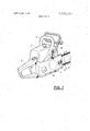
- FIG. 1 is a perspective view of a chain saw, power driven by an internal combustion engine and
- FIG. 2 is a side elevational view of a cover supporting the brake device, seen from the inside.
- the body 1 of the saw encloses an internal combustion engine. Said body is during the work held in a rear handle 2, provided with a throttle finger control and in a front handle shaped as a bow handle 3. From the body 1 of the saw, a bar 4 projects, around which a saw chain 5 runs in the direction of the arrow in theillustration. As is shown by means of broken lines a drum 7 is located inside a cover 6. On the drum a sprocket wheel is mounted for the drive of the chain 5 which is stretching around the wheel.
- the drum 7 is free-wheeling on the propulsion shaft of the motor, but is provided to be driven by said shaft by means of a centrifugal clutch including friction blocks in the drum 7 which are flung outwards against the inner wall of the drum, when the crankshaft has reached a certain speed.
- the cover 6 is arranged to retain the bar 4 by means of a plate 9 arranged for this purpose and pressed against the sword 4 by means of two nuts 8 threaded on stud bolts. (FIG. 2).
- the design described above is well known from all common power saws, and it should therefore not be necessary to make a more detailed description than the one above.
- the cover 6 supports a feeler organ in the shape of a tubular yoke 10.
- the outer portion of the tubular yoke 10 is located in front of the portion of the bow handle 3, which constitutes a grip for the hand, when the saw is used for pruning and similar operations.
- the tubular yoke 10 and the bow handle 3 here extend parallel to each other at a distance permitting the introduction of a hand gripping around thebow handle 3.
- the yoke 10 is designed in such a manner that its uppermost portion is located above the bow handle 3.
- the yoke 10 is pivotably mounted in a bearing 11 in the cover 6 by means of a pivot 12 which is resiliently held in the position mentioned above and illustrated in the drawings.
- the pivot 12 is arranged for radial as well as axial journalling and supports two projecting pins 13 and 14.
- the location of the outer periphery of the coupling drum 7 when the cover 6is mounted on the saw, is also evident from FIG 2.
- a brake band 16 provided with a brake lining 15.
- One of the ends of the band is fastened to a projection 17 of the cover 6 and the other part is fastened to a lever arm 18 which is pivotably mounted in a bearing 19 of the cover 6.
- the brake band 16 occupies the position mentioned at a distance from the periphery of the drum 7 and is thereby supported by two shoulders 20, 21 and the plate 9 of the cover 6.
- a tension spring 23 is hooked to the same end of the lever arm 18 to which the brake band 16 is attached, the other end of said spring being hooked to a projection 22 of the cover 6.
- the tension spring 23 is extended, thus tending to pivot the lever arm clockwise (as seen in FIG. 2) around its bearing 19.
- a pawl 24 which tends to pivot counterclockwise around a bearing 25 biased by a torsion spring 26, whereby its nose is kept against a ratcher surface 27 of an angular recess in the lever arm 18.
- the pin 13 In the normal position of the tubular yoke 10 the pin 13 is immediately above the pawl 24.
- the purpose to create the possibility of effectuating a brake operation to standstill within a predetermined time limit is obtained by the brake being actuated by discharge of a spring force, produced by a spring device which is adjustable.
- the purpose of producing the least possible strain on the driving mechanism in spite of the rapid braking action is according to the embodiment obtained by designing the brake as a friction brake, designed for a lowering of the necessary force for the ac tuating by means of a moderately friction driving.
- the same result can be obtained by employing other types of friction brakes, by way of example shoe brakes.
- the feeler organ for the triggering of the brake i.e., the tubular yoke 10 can also be of other designs than the shown, by way of example a design in which a mass by means of its inertia produces the necessary movement for the triggering of the brake when the saw is sub jected to a fling.
- Brake device for power saws especially power chain saws comprising a friction brake for the driving mechanism of the saw, spring means tending to bring said brake to braking position, trigger means positioned on the saw at one of the handles of the saw, pawl means connected to said brake, further spring means connected to and tending to bring said pawl means into a position in which it holds said brake in a non-braking position, said trigger means being capable of moving said pawl means out of engagement with said brake and leave it free to move to the braking position under the force of said first spring means when said trigger means is moved from the normal position to the second position which it would reach when struck by the hand of the saw operator at an occasional flinging movement of the saw tool.
- said brake is a brake band acting upon a cylindrical part of the driving mechanism of the saw, one end of said band as seen in the intended direction of rotation of said part of the driving mechanism having a fixed point of attachment relative to the bearing of the cylindrical part, a pivotally mounted lever connected to said first spring and the other end of said brake band and cooperating with said pawl means.
- Brake device for power saws especially power chain saws comprising a friction brake for the driving mechanism of the saw, spring means tending to bring said brake to braking position, trigger means positioned at one of the handles of the saw and movable between a normal position in which said brake is leaving the driving mechanism free to run and a second position in which said brake is activated, pawl means connected to said brake, further spring means connected to and capable of bringing said pawl means in a position in which it holds said brake in a non-braking position, said trigger means being capable of moving said pawl means out of engagement with said brake when said trigger means is moved from a normal position to a second position, said means comprising an arm pivotally mounted adjacent to said pawl means, an element carried by said arm outside of the pivoting axis of said arm and capable of acting upon said pawl to bring the same out its brakeholding position when said arm is pivoted by the moving of the trigger means to the second position.
- Brake device for power saws which have a front handle, cover and a driving mechanism which includes a friction drive clutch provided with a cylindrical drum, and comprising a friction brake for the driving mechanism, spring means connected to and tending to bring said brake to braking position, trigger means at one of the handles of the saw movable between a normal'posihaving a portion extending near to the handle and being mounted in a bearing on the cover enclosing the drum and said brake being a band brake provided to act upon the clutch drum and said band brake being enclosed and carried in the cover.
- a drum brake device comprising a yoke pivotally mounted on said cover and extending adjacent the supporting handle, a lever pivotally mounted in said cover and having a ratchet surface, a brake band encircling the drum and connected at one end to the cover and at its other end to said lever, resilient means tending to move said brake band to a drum braking position, a pawl pivotally mounted on the cover and normally engaging said ratchet surface holding said lever in a position retaining said brake band in a non-braking position against the pull of said resilient means, second resilient means tending to hold said pawl in its ratchet surface engaging position, and said yoke having projections, one projection positioned for moving said pawl out of its ratchet surface engaging position when said yoke is pivoted from the handle and the second projection positioned for moving said lever to its nonbraking position when said yoke is moved towards the handle.
Landscapes
- Engineering & Computer Science (AREA)
- General Engineering & Computer Science (AREA)
- Mechanical Engineering (AREA)
- Life Sciences & Earth Sciences (AREA)
- Wood Science & Technology (AREA)
- Forests & Forestry (AREA)
- Braking Arrangements (AREA)
- Sawing (AREA)
Abstract
A brake device for power saws having a supporting handle and a driving mechanism drum with a trigger means operable by an operator''s hand moving from said handle and striking a pivotal yoke adjacent said handle when the saw is inadvertently flung to one side during use, which yoke releases a pawl means normally retaining braking means around the drum in a non-braking position to allow resilient means to move the braking means to a drum braking position.
Description
Umted States Patent 1 1 1111 3,776,331
Gustafsson Dec. 4, 1973 [54] BRAKE-DEVICE FOR POWER SAWS 2,480,343 8/1949 Sully 188/166 1 Len-m 255211; .1122: 1:: :22/22 Sweden 3,485,326 12/1969 Wilkin l88/l36 [73] Assignee: Aktiebolaget Partner, Fack, Sweden [22] Filed: Apt 11 1972 Primary Examiner-Duane A. Reger App]. No.: 242,978
Foreign Application Priority Data Apr. 13, 1971 Sweden 4771/71 US. Cl 188/166, 30/381, 188/77 R Int. Cl B60t 13/04 Field of Search 30/371, 380-382;
References Cited UNITED STATES PATENTS 10/1934 McGifi'ert et a1. 188/166 X Attorney-William C. Linton A brake device for power saws having a supporting ABSTRACT handle and a driving mechanism drum with a trigger means operable by an operators hand moving from said handle and striking a pivotal yoke adjacent said handle when the saw is inadvertently flung to one side during use, which yoke releases a pawl means normally retaining braking means around the drum in a non-braking position to allow resilient means to move the braking means to a drum braking position.
6 Claims, 2 Drawing Figures PATENTED DEC 4 I975 SHEET 1 BF 2 BRAKE-DEVICE FOR POWER SAWS The present invention relates to a brake device for power saws especially power chain saws comprising a friction brake for the driving mechanism of thesaw chain arranged to be actuated by means of a feeler organ provided to react when an accident is threatening, for example by means of a trigger organ on one of the handles of the saw, against which trigger organ the hand of the operator of the saw is striking at a flinging movement of the saw.
The use of power chain saws involves great risks for body injuries, especially when used for pruning jobs. While performing this kind of work the portion of the saw chain which runs over the top of the bar supporting the same will easily come in contact with a solid object, by way of example a branch and will thereby produce a movement which will fling the whole saw upwards. Thereby it often happens that the operator of the saw lost his grip of the front handle of the saw, shaped as a bow, so that the saw chain gets in contact with the face or the upper body of the operator, with serious body injuries as a result.
In order to avoid that the chain in this manner causes injuries, protection means have been proposed, intended to bring the chain to stop at a sudden fling of the saw.
Such a protection means is by way of example known from the Swedish patent specification N9. 313 172 and comprises a feeler organ against which the hand of the saw operator will strike, in case it looses its grip of the bow handle. At the strike the feeler organ being displaced brings the internal combustion enginefor the chain saw drive to a stop by actuation of an ignition switch. Further there is an embodiment of a saw known, in which this protection means is combined with a friction brake acting upon the chain driving mechanism and actuated by the feeler organ. Said brake device has been made in order to reduce the time elapsed between the strike of the hand against the feeler organ and the standstill of the chain. The power to produce the brake action is taken from the strike of the hand against the feeler organ. Other solutions are known from the US. Pat. Specs. Nos. 3,361,165 and 3,485,327 which relate to saw designs in which stop pawls are brought to fall down against projections provided on a driving organ for the chain causing the same to stop. However, it can be established that the two first mentioned solutions exhibit the drawback that the device is not capable to carry out the stop of the chain quick enough. Also when a brake is incorporated into the design, the chain can still be moving, when it gets in contact with the operator of the saw, the risks of injuries therefore remain, especially because that the braking power depends upon the energy of the strike. The fact is that the time is so short as about 0,1 second from that a fling occurs to the chain is hitting the operator. The last mentioned devices on the otherv hand exhibit the drawback that the blow occurring between the stop pawl and the projection will be so violent that at least after repeated operations damage can arise in the driving mechanism.
It is an object of the present invention to provide a brake device for the purpose mentioned which provokes such a rapid stop of the chain at a fling that said chain independently of the force of the strike within a predetermined margin of time can be broughtto a stop before it has reached contact with theoperator of the saw, and which device in spite of this works so softly that damage in the brake device itself as well as in the power mechanism of the saw is avoided even by very frequent use.
It is another object of the invention to provide a means which retains the driving mechanism in locked position without stop of the motor; at inernal combustion engines a stop requires a new starting operation.
The objects of the invention are obtained by providing the brake to be kept in non-active position by means of a blocking mechanism and in said position subjected to the force of a spring which force is adjusted according to a predetermined braking time, and by that the feeler organ being arranged to bring the blocking mechanism to release the brake so that the spring actuates the same.
An embodiment of the invention is illustrated in the accompanying drawings which embodiment is described with reference to said drawings, in which:
FIG. 1 is a perspective view of a chain saw, power driven by an internal combustion engine and FIG. 2 is a side elevational view of a cover supporting the brake device, seen from the inside.
In FIG. 1 the body 1 of the saw encloses an internal combustion engine. Said body is during the work held in a rear handle 2, provided with a throttle finger control and in a front handle shaped as a bow handle 3. From the body 1 of the saw, a bar 4 projects, around which a saw chain 5 runs in the direction of the arrow in theillustration. As is shown by means of broken lines a drum 7 is located inside a cover 6. On the drum a sprocket wheel is mounted for the drive of the chain 5 which is stretching around the wheel. The drum 7 is free-wheeling on the propulsion shaft of the motor, but is provided to be driven by said shaft by means of a centrifugal clutch including friction blocks in the drum 7 which are flung outwards against the inner wall of the drum, when the crankshaft has reached a certain speed. The cover 6 is arranged to retain the bar 4 by means of a plate 9 arranged for this purpose and pressed against the sword 4 by means of two nuts 8 threaded on stud bolts. (FIG. 2). The design described above is well known from all common power saws, and it should therefore not be necessary to make a more detailed description than the one above.
As is further evident from FIG. 1 the cover 6 supports a feeler organ in the shape of a tubular yoke 10. The outer portion of the tubular yoke 10 is located in front of the portion of the bow handle 3, which constitutes a grip for the hand, when the saw is used for pruning and similar operations. The tubular yoke 10 and the bow handle 3 here extend parallel to each other at a distance permitting the introduction of a hand gripping around thebow handle 3. The yoke 10 is designed in such a manner that its uppermost portion is located above the bow handle 3.
According to FIG. 2 the yoke 10 is pivotably mounted in a bearing 11 in the cover 6 by means of a pivot 12 which is resiliently held in the position mentioned above and illustrated in the drawings. The pivot 12 is arranged for radial as well as axial journalling and supports two projecting pins 13 and 14. The location of the outer periphery of the coupling drum 7 when the cover 6is mounted on the saw, is also evident from FIG 2. At some distance from said periphery and encircling the greater part of the same extends a brake band 16 provided with a brake lining 15. One of the ends of the band is fastened to a projection 17 of the cover 6 and the other part is fastened to a lever arm 18 which is pivotably mounted in a bearing 19 of the cover 6. When the lever arm 18 occupies one of its extreme positions as illustrated in the figure, the brake band 16 occupies the position mentioned at a distance from the periphery of the drum 7 and is thereby supported by two shoulders 20, 21 and the plate 9 of the cover 6.
One end of a tension spring 23 is hooked to the same end of the lever arm 18 to which the brake band 16 is attached, the other end of said spring being hooked to a projection 22 of the cover 6. In the illustrated position of the lever arm 18 the tension spring 23 is extended, thus tending to pivot the lever arm clockwise (as seen in FIG. 2) around its bearing 19. However, this is prevented by a pawl 24 which tends to pivot counterclockwise around a bearing 25 biased by a torsion spring 26, whereby its nose is kept against a ratcher surface 27 of an angular recess in the lever arm 18. In the normal position of the tubular yoke 10 the pin 13 is immediately above the pawl 24.
The functioning is as follows: When working with the power saw the tubular yoke 10 and other parts of the brake device are in the positions illustrated in the figures and the yoke is retained in said position because of its resilient fixing. If the saw should fling so suddenly that the operator looses his grip of the bow handle 3, the hand will strike against the upper portion of the tubular yoke 10. Thereby the fixing force is overcome, and the yoke is pivoted counterclockwise around its bearing 12 (as seen in FIG. 2), thus in forwards direction in FIG. 1 towards the bar 4. The pin 13 is thereby displaced downwards and presses against the pawl 24, so that this pawl looses its contact with the ratcher surface 27, and the extended spring 23 pulls the lever arm 18 in clockwise direction. Owing to this the brake band 16 is tightened with the necessary force around the coupling drum 7 rotating in the direction of the arrow, so that said drum rapidly will be braked. The braking force produced by the spring 23 in this embodiment will be raised through the choised direction of rotation of the brake drum relative to the movable suspension point of the brake band.
As soon as the coupling drum 7 has been braked to a standstill also the chain is at standstill and the threatening of an accident by cutting has been avoided.
It can be assumed that the throttle control will be released practically instinctively when the fling occurs, so that the engine slows down to idling, whereby the centrifugal clutch is disengaged. Thus the motor can be kept going in spite of the locking of the drum and because the locking remains without any risk that the chain will begin to run again.
However, before the sawing operation can be resumed, it is necessary to first release the brake. This is done by moving the yoke 10 backwards in direction towards and over the bow handle 3 (in clockwise direction as seen in FIG. 2). Owing to this the pin 14 will come into contact with the lever arm and brings it from the position in which it tightens the brake band 16 against the force of the spring 23 to the position illustrated in FIG. 2. When this position has been reached, the pawl 24 by actuation of the spring 26 jumps into its blocking position against the ratcher surface 27 and retains the lever arm 18 with the spring 23 extended and the brake band disengaged from the clutch drum 7. The yoke now finally can be returned to its trigger position and thereby all the parts will occupy the original positions illustrated in FIG. 2.
The purpose to create the possibility of effectuating a brake operation to standstill within a predetermined time limit is obtained by the brake being actuated by discharge of a spring force, produced by a spring device which is adjustable. The purpose of producing the least possible strain on the driving mechanism in spite of the rapid braking action is according to the embodiment obtained by designing the brake as a friction brake, designed for a lowering of the necessary force for the ac tuating by means of a moderately friction driving. The same result can be obtained by employing other types of friction brakes, by way of example shoe brakes. The feeler organ for the triggering of the brake, i.e., the tubular yoke 10 can also be of other designs than the shown, by way of example a design in which a mass by means of its inertia produces the necessary movement for the triggering of the brake when the saw is sub jected to a fling. The above mentioned and other modifications can be imagined within the scope of the following claims for patent without departing from the fundamental idea of the invention.
I claim:
1. Brake device for power saws, especially power chain saws comprising a friction brake for the driving mechanism of the saw, spring means tending to bring said brake to braking position, trigger means positioned on the saw at one of the handles of the saw, pawl means connected to said brake, further spring means connected to and tending to bring said pawl means into a position in which it holds said brake in a non-braking position, said trigger means being capable of moving said pawl means out of engagement with said brake and leave it free to move to the braking position under the force of said first spring means when said trigger means is moved from the normal position to the second position which it would reach when struck by the hand of the saw operator at an occasional flinging movement of the saw tool.
2. Brake device according to claim 1, wherein said brake is a brake band acting upon a cylindrical part of the driving mechanism of the saw, one end of said band as seen in the intended direction of rotation of said part of the driving mechanism having a fixed point of attachment relative to the bearing of the cylindrical part, a pivotally mounted lever connected to said first spring and the other end of said brake band and cooperating with said pawl means.
3. Brake device for power saws, especially power chain saws comprising a friction brake for the driving mechanism of the saw, spring means tending to bring said brake to braking position, trigger means positioned at one of the handles of the saw and movable between a normal position in which said brake is leaving the driving mechanism free to run and a second position in which said brake is activated, pawl means connected to said brake, further spring means connected to and capable of bringing said pawl means in a position in which it holds said brake in a non-braking position, said trigger means being capable of moving said pawl means out of engagement with said brake when said trigger means is moved from a normal position to a second position, said means comprising an arm pivotally mounted adjacent to said pawl means, an element carried by said arm outside of the pivoting axis of said arm and capable of acting upon said pawl to bring the same out its brakeholding position when said arm is pivoted by the moving of the trigger means to the second position.
4. Brake device according to claim 3 wherein said arm carries a second element placed outside of the pivoting axis of said arm which second element, when said arm is pivoted by the moving of said trigger means to the normal position, is capable of acting upon a member of the brake to return the same to the position in which it is inactivated and further spring means tends to move said pawl means to its non-braking position.
5. Brake device for power saws which have a front handle, cover and a driving mechanism which includes a friction drive clutch provided with a cylindrical drum, and comprising a friction brake for the driving mechanism, spring means connected to and tending to bring said brake to braking position, trigger means at one of the handles of the saw movable between a normal'posihaving a portion extending near to the handle and being mounted in a bearing on the cover enclosing the drum and said brake being a band brake provided to act upon the clutch drum and said band brake being enclosed and carried in the cover.
6. In a power saw having a cover, supporting handle on said cover and driving mechanism drum, a drum brake device comprising a yoke pivotally mounted on said cover and extending adjacent the supporting handle, a lever pivotally mounted in said cover and having a ratchet surface, a brake band encircling the drum and connected at one end to the cover and at its other end to said lever, resilient means tending to move said brake band to a drum braking position, a pawl pivotally mounted on the cover and normally engaging said ratchet surface holding said lever in a position retaining said brake band in a non-braking position against the pull of said resilient means, second resilient means tending to hold said pawl in its ratchet surface engaging position, and said yoke having projections, one projection positioned for moving said pawl out of its ratchet surface engaging position when said yoke is pivoted from the handle and the second projection positioned for moving said lever to its nonbraking position when said yoke is moved towards the handle.
Claims (6)
1. Brake device for power saws, especially power chain saws comprising a friction brake for the driving mechanism of the saw, spring means tending to bring said brake to braking position, trigger means positioned on the saw at one of the handles of the saw, pawl means connected to said brake, further spring means connected to and tending to bring said pawl means into a position in which it holds said brake in a non-braking position, said trigger means being capable of moving said pawl means out of engagement with said brake and leave it free to move to the braking position under the force of said first spring means when said trigger means is moved from the normal position to the second position which it would reach when struck by the hand of the saw operator at an occasional flinging movement of the saw tool.
2. Brake device according to claim 1, wherein said brake is a brake band acting upon a cylindrical part of the driving mechanism of the saw, one end of said band as seen in the intended direction of rotation of said part of the driving mechanism having a fixed point of attachment relative to the bearing of the cylindrical part, a pivotally mounted lever connected to said first spring and the other end of said brake band and cooperating with said pawl means.
3. Brake device for power saws, especially power chain saws comprising a friction brake for the driving mechanism of the saw, spring means tending to bring said brake to braking position, trigger means positioned at one of the handles of the saw and movable between a normal position in which said brake is leaving the driving mechanism free to run and a second position in which said brake is activated, pawl means connected to said brake, further spring means connected to and capable of bringing said pawl means in a position in which it holds said brake in a non-braking position, said trigger means being capable of moving said pawl means out of engagement with said brake when said trigger means is moved from a normal position to a second position, said means comprising an arm pivotally mounted adjacent to said pawl means, an element carried by said arm outside of the pivoting axis of said arm and capable of acting upon said pawl to bring the same out its brake holding position when said arm is pivoted by the moving of the trigger means to the second position.
4. Brake device according to claim 3 wherein said arm carries a second element placed outside of the pivoting axis of said arm which second element, when said arm is pivoted by the moving of said trigger means to the normal position, is capable of acting upon a member of the brake to return the same to the position in which it is inactivated and further spring means tends to move said pawl means to its non-braking position.
5. Brake device for power saws which have a front handle, cover and a driving mechanism which includes a friction drive clutch provided with a cylindrical drum, and comprising a friction brake for the driving mechanism, spring means connected to and tending to bring said brake to braking position, trigger means at one of the handles of the saw movable between a normal position in which said brake is leaving the driving mechanism free to run and a second position in which said brake is activated, pawl means connected to Said brake, further spring means connected to and capable of bringing said pawl means to a position in which it is in engagement with said brake, holding the same in a non-activated position whereby the trigger means is provided to bring the pawl means out of engagement with the brake when the trigger means is moved from a normal position to a second position, said trigger means having a portion extending near to the handle and being mounted in a bearing on the cover enclosing the drum and said brake being a band brake provided to act upon the clutch drum and said band brake being enclosed and carried in the cover.
6. In a power saw having a cover, supporting handle on said cover and driving mechanism drum, a drum brake device comprising a yoke pivotally mounted on said cover and extending adjacent the supporting handle, a lever pivotally mounted in said cover and having a ratchet surface, a brake band encircling the drum and connected at one end to the cover and at its other end to said lever, resilient means tending to move said brake band to a drum braking position, a pawl pivotally mounted on the cover and normally engaging said ratchet surface holding said lever in a position retaining said brake band in a non-braking position against the pull of said resilient means, second resilient means tending to hold said pawl in its ratchet surface engaging position, and said yoke having projections, one projection positioned for moving said pawl out of its ratchet surface engaging position when said yoke is pivoted from the handle and the second projection positioned for moving said lever to its non-braking position when said yoke is moved towards the handle.
Applications Claiming Priority (1)
| Application Number | Priority Date | Filing Date | Title |
|---|---|---|---|
| SE7104771A SE390131B (en) | 1971-04-13 | 1971-04-13 | BRAKE DEVICE FOR MOTORSAWS |
Publications (1)
| Publication Number | Publication Date |
|---|---|
| US3776331A true US3776331A (en) | 1973-12-04 |
Family
ID=20264933
Family Applications (1)
| Application Number | Title | Priority Date | Filing Date |
|---|---|---|---|
| US00242978A Expired - Lifetime US3776331A (en) | 1971-04-13 | 1972-04-11 | Brake-device for power saws |
Country Status (6)
| Country | Link |
|---|---|
| US (1) | US3776331A (en) |
| JP (1) | JPS5316157B1 (en) |
| CA (1) | CA976847A (en) |
| DE (1) | DE2217707C3 (en) |
| GB (1) | GB1385216A (en) |
| SE (1) | SE390131B (en) |
Cited By (43)
| Publication number | Priority date | Publication date | Assignee | Title |
|---|---|---|---|---|
| US3839795A (en) * | 1973-04-26 | 1974-10-08 | Mc Culloch Corp | Chain saw safety method and apparatus |
| US3923126A (en) * | 1974-06-25 | 1975-12-02 | Textron Inc | Band type brake for a chain saw |
| US3934345A (en) * | 1974-10-15 | 1976-01-27 | Mcculloch Corporation | Snap-acting over-center chain saw safety brake and method of operation thereof |
| US3937306A (en) * | 1973-08-29 | 1976-02-10 | Husqvarna Ab | Automatic brake actuator for a chain saw |
| US3961433A (en) * | 1974-06-21 | 1976-06-08 | The Raymond Lee Organization Inc. | Picture poster viewer |
| FR2291697A1 (en) * | 1974-11-22 | 1976-06-18 | Kaaz Machinery Co Ltd | PORTABLE MOWER-BRUSHCUTTER |
| US3964333A (en) * | 1974-10-15 | 1976-06-22 | Mcculloch Corporation | Safety braking mechanism for a portable chain saw |
| US3974566A (en) * | 1975-09-08 | 1976-08-17 | Mcculloch Corporation | Method and apparatus for arresting movement of a chain saw cutter chain |
| US3991864A (en) * | 1973-10-25 | 1976-11-16 | Andreas Stihl Maschinenfabrik | Motor saw, especially motor chain saw |
| US3991469A (en) * | 1974-10-15 | 1976-11-16 | Mcculloch Corporation | Safety braking mechanism for a portable chain saw |
| US3992779A (en) * | 1973-12-21 | 1976-11-23 | Textron, Inc. | Chain brake for chain saw |
| US4026392A (en) * | 1974-10-15 | 1977-05-31 | Mcculloch Corporation | Snap-acting over-center chain saw safety brake and method of operation thereof |
| US4057900A (en) * | 1975-06-04 | 1977-11-15 | Ab Partner | Power saw |
| US4059895A (en) * | 1974-10-15 | 1977-11-29 | Mcculloch Corporation | Full position safety brake for portable chain saw |
| US4091896A (en) * | 1976-01-22 | 1978-05-30 | Firma Andreas Stihl | Chain saw braking mechanism |
| US4121339A (en) * | 1977-08-10 | 1978-10-24 | Milovan Nikolich | Safety brake mechanism for chain saws |
| US4156477A (en) * | 1977-09-14 | 1979-05-29 | Kioritz Corporation | Braking system of chain saw |
| US4197640A (en) * | 1978-09-18 | 1980-04-15 | Beaird-Poulan Division, Emerson Electric Co. | Safety braking apparatus for portable chain saw |
| US4246701A (en) * | 1978-05-18 | 1981-01-27 | Jonsereds Ab | Safety braking device for a portable power saw |
| US4310972A (en) * | 1979-12-28 | 1982-01-19 | Trail Manufacturing Limited | Brake control assembly |
| US4334357A (en) * | 1980-08-08 | 1982-06-15 | Black & Decker Inc. | Safety braking apparatus for a portable chain saw |
| US4426563A (en) | 1983-03-14 | 1984-01-17 | Victor A. Grogan | Chain saw safety switch |
| US4474269A (en) * | 1981-06-04 | 1984-10-02 | Andreas Stihl | Braking device for a power chain saw |
| DE3324628A1 (en) * | 1983-07-08 | 1985-01-17 | Fa. Andreas Stihl, 7050 Waiblingen | Chain brake device |
| US4586588A (en) * | 1983-08-01 | 1986-05-06 | Kioritz Corporation | Chain saw safety-brake system |
| US4630372A (en) * | 1983-09-07 | 1986-12-23 | Kioritz Corporation | Front handle support means of portable chain saw |
| US4651423A (en) * | 1986-04-23 | 1987-03-24 | Grogan Victor A | Chain saw cutting chain safety stop |
| US4721193A (en) * | 1984-10-18 | 1988-01-26 | Kioritz Corporation | Emergency braking system of chain saw |
| AU576035B2 (en) * | 1985-01-29 | 1988-08-11 | Kenneth Wallmark | Braking device for chain saw |
| US4793064A (en) * | 1986-05-02 | 1988-12-27 | Kioritz Corporation | Chain saw safety braking device |
| US6094822A (en) * | 1998-02-26 | 2000-08-01 | Andreas Stihl Ag & Co. | Hedge clippers |
| US6814192B2 (en) * | 2001-02-07 | 2004-11-09 | Dolmar Gmbh | Device for braking a motor shaft |
| US20060060439A1 (en) * | 2004-09-22 | 2006-03-23 | Norio Shirokoshi | Brake-equipped retracting mechanism for retractable member |
| US20060102437A1 (en) * | 2004-11-17 | 2006-05-18 | Masato Nara | Brake system of working machine |
| US20070011888A1 (en) * | 2005-07-12 | 2007-01-18 | Myers Kent J | Chainsaw throttle and brake mechanisms |
| US20070295298A1 (en) * | 2004-11-15 | 2007-12-27 | Dolmar Gmbh | Starting Brake for a Hedge Clipper |
| US20080283650A1 (en) * | 2005-06-29 | 2008-11-20 | Norio Shirokoshi | Brake-Equipped Retracting Device for Retractable Member |
| US20150258703A1 (en) * | 2012-10-03 | 2015-09-17 | Hilti Aktiengesellschaft | Hand-Held Tool Apparatus with a Braking Device for Braking of a Machining Tool |
| US20150260241A1 (en) * | 2012-10-03 | 2015-09-17 | Hilti Aktiengesellschaft | Hand-Operated Tool Device With A Brake Mechanism For Braking A Machining Tool |
| US20150258658A1 (en) * | 2012-10-03 | 2015-09-17 | Hilti Aktiengesellschaft | Hand-Held Tool Apparatus with a Braking Device for Braking a Machining Tool |
| CN112352651A (en) * | 2020-11-20 | 2021-02-12 | 永康市南征工贸股份有限公司 | Adjustable prevents accidental injury people's electric chain saw |
| US12064894B2 (en) | 2020-09-04 | 2024-08-20 | Milwaukee Electric Tool Corporation | Chainsaw |
| EP3885599B1 (en) * | 2017-08-21 | 2025-12-03 | Valmont Industries, Inc. | System and method for providing drive shaft braking for irrigation machines |
Families Citing this family (7)
| Publication number | Priority date | Publication date | Assignee | Title |
|---|---|---|---|---|
| CA1028227A (en) * | 1974-10-15 | 1978-03-21 | Robert E. Frederickson | Safety braking mechanism for a portable chain saw |
| JPS57159258U (en) * | 1981-03-30 | 1982-10-06 | ||
| FR2517586A1 (en) * | 1981-12-09 | 1983-06-10 | Trail Manufacturing Ltd | Brake control assembly for chain saw - has operating lever with guard portion adjacent handle carried by saw housing and hub portion alongside housing |
| SE8300200L (en) * | 1982-01-18 | 1983-07-19 | Sachs Dolmar Gmbh | BRAKE DEVICE FOR BRAKEING THE CHAIN CHAIN AT A TREADABLE CHAIN SAW CHAIN |
| DE3608523A1 (en) * | 1986-03-14 | 1987-09-17 | Bosch Gmbh Robert | QUICK STOP DEVICE FOR STOPPING A SAW CHAIN OF A PORTABLE MOTOR CHAIN SAW |
| EP0440827B1 (en) * | 1990-01-31 | 1994-07-06 | Dolmar GmbH | Braking device for a motorized hand saw, in particular a chain saw |
| JP6583436B2 (en) * | 2016-01-30 | 2019-10-02 | 工機ホールディングス株式会社 | Chain saw |
Citations (5)
| Publication number | Priority date | Publication date | Assignee | Title |
|---|---|---|---|---|
| US1976406A (en) * | 1932-02-15 | 1934-10-09 | Clyde Iron Works | Safety brake |
| US2480343A (en) * | 1943-01-21 | 1949-08-30 | American Car & Foundry Co | Safety band brake for high-speed tools |
| US3228177A (en) * | 1964-07-29 | 1966-01-11 | Coates Leroy | Safety device for power equipment |
| US3292742A (en) * | 1964-11-03 | 1966-12-20 | Clark Equipment Co | Brake |
| US3485326A (en) * | 1967-10-20 | 1969-12-23 | Mcculloch Corp | Magnetic stopping device |
-
1971
- 1971-04-13 SE SE7104771A patent/SE390131B/en unknown
-
1972
- 1972-04-11 US US00242978A patent/US3776331A/en not_active Expired - Lifetime
- 1972-04-12 GB GB1690472A patent/GB1385216A/en not_active Expired
- 1972-04-12 CA CA139,548A patent/CA976847A/en not_active Expired
- 1972-04-13 JP JP3732272A patent/JPS5316157B1/ja active Pending
- 1972-04-13 DE DE2217707A patent/DE2217707C3/en not_active Expired
Patent Citations (5)
| Publication number | Priority date | Publication date | Assignee | Title |
|---|---|---|---|---|
| US1976406A (en) * | 1932-02-15 | 1934-10-09 | Clyde Iron Works | Safety brake |
| US2480343A (en) * | 1943-01-21 | 1949-08-30 | American Car & Foundry Co | Safety band brake for high-speed tools |
| US3228177A (en) * | 1964-07-29 | 1966-01-11 | Coates Leroy | Safety device for power equipment |
| US3292742A (en) * | 1964-11-03 | 1966-12-20 | Clark Equipment Co | Brake |
| US3485326A (en) * | 1967-10-20 | 1969-12-23 | Mcculloch Corp | Magnetic stopping device |
Cited By (50)
| Publication number | Priority date | Publication date | Assignee | Title |
|---|---|---|---|---|
| US3839795A (en) * | 1973-04-26 | 1974-10-08 | Mc Culloch Corp | Chain saw safety method and apparatus |
| US3937306A (en) * | 1973-08-29 | 1976-02-10 | Husqvarna Ab | Automatic brake actuator for a chain saw |
| US3991864A (en) * | 1973-10-25 | 1976-11-16 | Andreas Stihl Maschinenfabrik | Motor saw, especially motor chain saw |
| US3992779A (en) * | 1973-12-21 | 1976-11-23 | Textron, Inc. | Chain brake for chain saw |
| US3961433A (en) * | 1974-06-21 | 1976-06-08 | The Raymond Lee Organization Inc. | Picture poster viewer |
| US3923126A (en) * | 1974-06-25 | 1975-12-02 | Textron Inc | Band type brake for a chain saw |
| US4026392A (en) * | 1974-10-15 | 1977-05-31 | Mcculloch Corporation | Snap-acting over-center chain saw safety brake and method of operation thereof |
| US3964333A (en) * | 1974-10-15 | 1976-06-22 | Mcculloch Corporation | Safety braking mechanism for a portable chain saw |
| US3991469A (en) * | 1974-10-15 | 1976-11-16 | Mcculloch Corporation | Safety braking mechanism for a portable chain saw |
| US3934345A (en) * | 1974-10-15 | 1976-01-27 | Mcculloch Corporation | Snap-acting over-center chain saw safety brake and method of operation thereof |
| US4059895A (en) * | 1974-10-15 | 1977-11-29 | Mcculloch Corporation | Full position safety brake for portable chain saw |
| FR2291697A1 (en) * | 1974-11-22 | 1976-06-18 | Kaaz Machinery Co Ltd | PORTABLE MOWER-BRUSHCUTTER |
| US4006528A (en) * | 1974-11-22 | 1977-02-08 | Kaaz Machinery Co. Ltd. | Portable grass and brush cutter with brake and clutch |
| US4057900A (en) * | 1975-06-04 | 1977-11-15 | Ab Partner | Power saw |
| US3974566A (en) * | 1975-09-08 | 1976-08-17 | Mcculloch Corporation | Method and apparatus for arresting movement of a chain saw cutter chain |
| US4091896A (en) * | 1976-01-22 | 1978-05-30 | Firma Andreas Stihl | Chain saw braking mechanism |
| US4121339A (en) * | 1977-08-10 | 1978-10-24 | Milovan Nikolich | Safety brake mechanism for chain saws |
| US4156477A (en) * | 1977-09-14 | 1979-05-29 | Kioritz Corporation | Braking system of chain saw |
| US4246701A (en) * | 1978-05-18 | 1981-01-27 | Jonsereds Ab | Safety braking device for a portable power saw |
| US4197640A (en) * | 1978-09-18 | 1980-04-15 | Beaird-Poulan Division, Emerson Electric Co. | Safety braking apparatus for portable chain saw |
| EP0020457A4 (en) * | 1978-09-18 | 1981-02-04 | Beaird Poulan Div | Safety braking apparatus for portable chain saw. |
| US4310972A (en) * | 1979-12-28 | 1982-01-19 | Trail Manufacturing Limited | Brake control assembly |
| US4334357A (en) * | 1980-08-08 | 1982-06-15 | Black & Decker Inc. | Safety braking apparatus for a portable chain saw |
| US4474269A (en) * | 1981-06-04 | 1984-10-02 | Andreas Stihl | Braking device for a power chain saw |
| US4426563A (en) | 1983-03-14 | 1984-01-17 | Victor A. Grogan | Chain saw safety switch |
| DE3324628A1 (en) * | 1983-07-08 | 1985-01-17 | Fa. Andreas Stihl, 7050 Waiblingen | Chain brake device |
| US4586588A (en) * | 1983-08-01 | 1986-05-06 | Kioritz Corporation | Chain saw safety-brake system |
| US4630372A (en) * | 1983-09-07 | 1986-12-23 | Kioritz Corporation | Front handle support means of portable chain saw |
| US4721193A (en) * | 1984-10-18 | 1988-01-26 | Kioritz Corporation | Emergency braking system of chain saw |
| AU576035B2 (en) * | 1985-01-29 | 1988-08-11 | Kenneth Wallmark | Braking device for chain saw |
| US4651423A (en) * | 1986-04-23 | 1987-03-24 | Grogan Victor A | Chain saw cutting chain safety stop |
| US4793064A (en) * | 1986-05-02 | 1988-12-27 | Kioritz Corporation | Chain saw safety braking device |
| US6094822A (en) * | 1998-02-26 | 2000-08-01 | Andreas Stihl Ag & Co. | Hedge clippers |
| US6814192B2 (en) * | 2001-02-07 | 2004-11-09 | Dolmar Gmbh | Device for braking a motor shaft |
| US20060060439A1 (en) * | 2004-09-22 | 2006-03-23 | Norio Shirokoshi | Brake-equipped retracting mechanism for retractable member |
| US7293632B2 (en) * | 2004-09-22 | 2007-11-13 | Harmonic Ad, Inc. | Brake-equipped retracting mechanism for retractable member |
| US7617809B2 (en) * | 2004-11-15 | 2009-11-17 | Dolmar Gmbh | Starting brake for a hedge clipper |
| US20070295298A1 (en) * | 2004-11-15 | 2007-12-27 | Dolmar Gmbh | Starting Brake for a Hedge Clipper |
| US20060102437A1 (en) * | 2004-11-17 | 2006-05-18 | Masato Nara | Brake system of working machine |
| US7686141B2 (en) * | 2005-06-29 | 2010-03-30 | Harmonic Ad, Inc. | Brake-equipped retracting device for retractable member |
| US20080283650A1 (en) * | 2005-06-29 | 2008-11-20 | Norio Shirokoshi | Brake-Equipped Retracting Device for Retractable Member |
| US7200941B2 (en) * | 2005-07-12 | 2007-04-10 | Myers Kent J | Chainsaw throttle and brake mechanisms |
| US20070011888A1 (en) * | 2005-07-12 | 2007-01-18 | Myers Kent J | Chainsaw throttle and brake mechanisms |
| US20150258703A1 (en) * | 2012-10-03 | 2015-09-17 | Hilti Aktiengesellschaft | Hand-Held Tool Apparatus with a Braking Device for Braking of a Machining Tool |
| US20150260241A1 (en) * | 2012-10-03 | 2015-09-17 | Hilti Aktiengesellschaft | Hand-Operated Tool Device With A Brake Mechanism For Braking A Machining Tool |
| US20150258658A1 (en) * | 2012-10-03 | 2015-09-17 | Hilti Aktiengesellschaft | Hand-Held Tool Apparatus with a Braking Device for Braking a Machining Tool |
| EP3885599B1 (en) * | 2017-08-21 | 2025-12-03 | Valmont Industries, Inc. | System and method for providing drive shaft braking for irrigation machines |
| US12064894B2 (en) | 2020-09-04 | 2024-08-20 | Milwaukee Electric Tool Corporation | Chainsaw |
| CN112352651A (en) * | 2020-11-20 | 2021-02-12 | 永康市南征工贸股份有限公司 | Adjustable prevents accidental injury people's electric chain saw |
| CN112352651B (en) * | 2020-11-20 | 2022-01-07 | 永康市南征工贸股份有限公司 | An adjustable electric chain saw for preventing accidental injury |
Also Published As
| Publication number | Publication date |
|---|---|
| SE390131B (en) | 1976-12-06 |
| DE2217707A1 (en) | 1972-10-19 |
| CA976847A (en) | 1975-10-28 |
| DE2217707C3 (en) | 1980-08-28 |
| JPS5316157B1 (en) | 1978-05-30 |
| GB1385216A (en) | 1975-02-26 |
| DE2217707B2 (en) | 1978-08-17 |
Similar Documents
| Publication | Publication Date | Title |
|---|---|---|
| US3776331A (en) | Brake-device for power saws | |
| US5480009A (en) | Brake system with two independent mechanical brakes | |
| US4197640A (en) | Safety braking apparatus for portable chain saw | |
| US3785465A (en) | Centrifugal clutches in series with brake | |
| JPH0219214Y2 (en) | ||
| US4324045A (en) | Motor chain saw with dynamic safety braking device | |
| US3664390A (en) | Safety means for power-driven chain saws | |
| US5358062A (en) | Portable handheld drilling apparatus | |
| US3991469A (en) | Safety braking mechanism for a portable chain saw | |
| US4420885A (en) | Power tool with improved braking device | |
| US3937306A (en) | Automatic brake actuator for a chain saw | |
| US4793064A (en) | Chain saw safety braking device | |
| US4057900A (en) | Power saw | |
| US4553326A (en) | Chain saw braking system | |
| JPH0251050B2 (en) | ||
| JPH0219216Y2 (en) | ||
| US4302879A (en) | Safety braking apparatus for portable chain saw | |
| JPH0378242B2 (en) | ||
| US7200941B2 (en) | Chainsaw throttle and brake mechanisms | |
| JPH0157641B2 (en) | ||
| US4328617A (en) | Safety brake mechanism for power chain saws | |
| US20080092399A1 (en) | Chainsaw throttle and brake mechanisms | |
| EP2969426B1 (en) | Chainsaw with coast brake/chainbrake mechanism | |
| US4651423A (en) | Chain saw cutting chain safety stop | |
| US4077125A (en) | Automatic safety brake for chain saw |