EP0062706A2 - Dispositif de chauffage - Google Patents
Dispositif de chauffage Download PDFInfo
- Publication number
- EP0062706A2 EP0062706A2 EP81110398A EP81110398A EP0062706A2 EP 0062706 A2 EP0062706 A2 EP 0062706A2 EP 81110398 A EP81110398 A EP 81110398A EP 81110398 A EP81110398 A EP 81110398A EP 0062706 A2 EP0062706 A2 EP 0062706A2
- Authority
- EP
- European Patent Office
- Prior art keywords
- generator
- heating
- heating device
- heat
- cooling
- Prior art date
- Legal status (The legal status is an assumption and is not a legal conclusion. Google has not performed a legal analysis and makes no representation as to the accuracy of the status listed.)
- Granted
Links
Images


Classifications
-
- F—MECHANICAL ENGINEERING; LIGHTING; HEATING; WEAPONS; BLASTING
- F02—COMBUSTION ENGINES; HOT-GAS OR COMBUSTION-PRODUCT ENGINE PLANTS
- F02G—HOT GAS OR COMBUSTION-PRODUCT POSITIVE-DISPLACEMENT ENGINE PLANTS; USE OF WASTE HEAT OF COMBUSTION ENGINES; NOT OTHERWISE PROVIDED FOR
- F02G5/00—Profiting from waste heat of combustion engines, not otherwise provided for
-
- B—PERFORMING OPERATIONS; TRANSPORTING
- B60—VEHICLES IN GENERAL
- B60H—ARRANGEMENTS OF HEATING, COOLING, VENTILATING OR OTHER AIR-TREATING DEVICES SPECIALLY ADAPTED FOR PASSENGER OR GOODS SPACES OF VEHICLES
- B60H1/00—Heating, cooling or ventilating [HVAC] devices
- B60H1/02—Heating, cooling or ventilating [HVAC] devices the heat being derived from the propulsion plant
- B60H1/03—Heating, cooling or ventilating [HVAC] devices the heat being derived from the propulsion plant and from a source other than the propulsion plant
-
- F—MECHANICAL ENGINEERING; LIGHTING; HEATING; WEAPONS; BLASTING
- F24—HEATING; RANGES; VENTILATING
- F24V—COLLECTION, PRODUCTION OR USE OF HEAT NOT OTHERWISE PROVIDED FOR
- F24V99/00—Subject matter not provided for in other main groups of this subclass
-
- H—ELECTRICITY
- H02—GENERATION; CONVERSION OR DISTRIBUTION OF ELECTRIC POWER
- H02K—DYNAMO-ELECTRIC MACHINES
- H02K5/00—Casings; Enclosures; Supports
- H02K5/04—Casings or enclosures characterised by the shape, form or construction thereof
- H02K5/20—Casings or enclosures characterised by the shape, form or construction thereof with channels or ducts for flow of cooling medium
- H02K5/203—Casings or enclosures characterised by the shape, form or construction thereof with channels or ducts for flow of cooling medium specially adapted for liquids, e.g. cooling jackets
-
- F—MECHANICAL ENGINEERING; LIGHTING; HEATING; WEAPONS; BLASTING
- F01—MACHINES OR ENGINES IN GENERAL; ENGINE PLANTS IN GENERAL; STEAM ENGINES
- F01P—COOLING OF MACHINES OR ENGINES IN GENERAL; COOLING OF INTERNAL-COMBUSTION ENGINES
- F01P2060/00—Cooling circuits using auxiliaries
- F01P2060/18—Heater
- F01P2060/185—Heater for alternators or generators
-
- Y—GENERAL TAGGING OF NEW TECHNOLOGICAL DEVELOPMENTS; GENERAL TAGGING OF CROSS-SECTIONAL TECHNOLOGIES SPANNING OVER SEVERAL SECTIONS OF THE IPC; TECHNICAL SUBJECTS COVERED BY FORMER USPC CROSS-REFERENCE ART COLLECTIONS [XRACs] AND DIGESTS
- Y02—TECHNOLOGIES OR APPLICATIONS FOR MITIGATION OR ADAPTATION AGAINST CLIMATE CHANGE
- Y02T—CLIMATE CHANGE MITIGATION TECHNOLOGIES RELATED TO TRANSPORTATION
- Y02T10/00—Road transport of goods or passengers
- Y02T10/10—Internal combustion engine [ICE] based vehicles
- Y02T10/12—Improving ICE efficiencies
Definitions
- the invention relates to a heating device according to the preamble of the main claim.
- Heating devices for motor vehicles in a variety of configurations are already known, in which a heat medium circuit is provided with which it is possible to supply or remove heat from the drive motor and / or to heat the passenger compartment.
- the heating medium is generally water or air, which are circulated by a cooling water pump or a fan in the heating medium circuit.
- additional heaters for the drive motor and / or passenger compartment, which are based on the combustion of fuel, on a change in the physical state of a heating medium or on electrical heating mediums.
- additional generators i.e. in addition to the usual generators of the motor vehicle, there are additional generators which supply electrical energy for operating the additional heater.
- the heating device according to the invention with the characterizing features of the main claim has the advantage that additional power loss in the form of waste heat is used for the heating medium circuit, so that an even more perfect utilization of the primary energy used is possible.
- the waste heat from at least one conventional motor vehicle generator is removed via a cooling jacket which is part of a heat medium circuit (water or air) of the motor vehicle for heating the drive motor and / or the passenger compartment.
- a heating generator also advantageously allows a heating generator to be provided on the same drive shaft in addition to the conventional generator in a manner known per se, the power loss of the heating generator also being able to be dissipated in the form of waste heat via the cooling jacket of a common housing of generator and heating generator.
- the existing heat dissipation from the generator and the heating generator is used to the effect that the heating generator is not used to generate electrical energy, but rather directly to generate thermal energy, for example by short-circuiting the stator winding or by designing it as an eddy current brake.
- an internal, closed air cooling circuit is also provided, which is generated by the fan wheel which is usually provided for generators. It is thus advantageously possible to remove the waste heat from the parts of the generator or generators that are not in direct heat-conducting contact with the cooling jacket.
- a particularly good efficiency is achieved according to the invention in that the electrical energy generated by the heating generator is converted into heat in heating resistors, these heating resistors being thermally in close contact with the heating generator or with the usual generator, with this compact arrangement additionally saving wiring.
- a system with a heating device with air cooling can be represented in a particularly simple manner and with only slight deviations from conventional air heating devices, with which a heating with and without a heating generator is possible with the greatest possible utilization of the waste heat. It is also possible to effect a separate generator cooling by forcibly dissipating the heat loss, this waste heat can be dissipated directly to the outside in summer operation, so that overheating of the generator can be avoided and the generator can be used for higher outputs with the same structural size.
- FIG. 1 shows a schematic illustration of a water / heat medium circuit of a motor vehicle according to the invention
- Figure 2a to e is a schematic representation of an air-heat medium circuit of a motor vehicle according to the invention
- 3a to c show a sectional view through a conventional motor vehicle generator with means for dissipating the power loss
- 4a to c show a seal for a generator according to FIG. 3
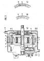
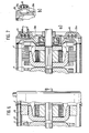
- FIG. 5 shows a sectional view through a tandem arrangement of conventional generator and heating generator with means for dissipating the power loss
- FIG. 6 shows a sectional view through a tandem arrangement of a conventional generator and heating generator in the form of an eddy current brake with means for dissipating the power loss
- Figure 7 is an illustration of heating resistors included in the generator.
- a heat medium pump for example a cooling water pump of a motor vehicle
- the heat medium pump 1 is connected via a line 2 to a cooling water jacket 3 of the drive motor, and this is connected via line 4 to a housing 5 in which a conventional generator 6 and a heating generator 7 are located.
- the housing 5 is in turn connected via a line 9 to a heat exchanger 10 which has an inflow opening 11 and an outflow opening 12.
- the heat exchanger 10 is in turn connected to the heat medium pump 1 via a line 13, which results in an overall closed heat medium circuit.
- the usual generator 6 serves to supply the usual consumers of the motor vehicle, as indicated by a battery 14, ignition system 15 and lighting 16, while the heating generator 7 - as will be described below for some exemplary embodiments - for generating electrical energy for an additional heater 17 or is used to generate thermal energy.
- FIG. 2a to d schematically show a further embodiment of a heat medium circuit according to the invention for a heating device, air being used as the heat medium.
- the circuit has two fresh air inlets 50, 51 which lead to a cross distributor 52 in which a first pipe slide is rotatably mounted.
- the first tube slide 53 consists of a rotatable tube, by means of which an air flow in the direction of the tube axis is possible and is blocked perpendicular to the tube axis.
- the first pipe slide 53 is in the position shown in FIG set below 45 0 , so that an air throughput on both sides of the first slide valve 53 is possible, as indicated by the arrows.
- a blower 54 is arranged between a fresh air insert 51 and the cross distributor 52.
- a line 55 leads from the cross distributor 52 to the housing 5, in which the usual generator 6 and the heating generator 7 are arranged.
- the generators 6, 7 are in a good heat-conducting connection with cooling channels 65 through which the air flows from the line 55 and dissipates the heat loss from the generators 6, 7.
- a line 59 leads from the housing 5 to a heat exchanger 61, to which a line 60 leads from a triangular distributor 57, in which a second pipe slide 58 is rotatably arranged and which in turn is connected to the cross distributor 52 via a line 56.
- the second pipe slide 58 has the same function as the first pipe slide 53.
- a line 62 also leads from the triangular distributor 57 to the outflow line 63 of the heat exchanger 61 and from there to an air outlet 64.
- a further triangular distributor 70 is arranged with a third pipe slide 71, the branch of which leads to an air outlet 72, the third pipe slide 71 being operatively connected to a blower 73 which is arranged in the fresh air inlet 50.
- FIGS. 2d and e show two operating positions of the triangular distributor 57.
- the cross distributor 52 is in the position shown in FIG. 2b ("heating generator off"), which corresponds to the position in accordance with FIG. 2a
- the fresh air inlet 51 is connected via the blower 54 to the line 56 leading to the delta distributor 57 Connection; the fresh air inlet 50 is connected to the line 55 leading to the housing 5.
- the triangular distributor 57 (“cold”) shown in FIGS. 2a and 2e, fresh air is accordingly conveyed from the fresh air inlet 51, possibly with the blower 54 switched on, via the lines 56, 62, 63 to the air outlet 64 of the passenger compartment.
- the triangular distributor 57 is switched to the position ("warm") shown in FIG. 2d, the line 56 is connected to the line 60 and thus to the heat exchanger 61, so that it flows from the fresh air inlet 51 via the blower 54 into the line 56 injected fresh air is fed via line 60 to heat exchanger 61, is heated there and is fed as warm air via line 63 to air outlet 64 of the passenger compartment.
- a cold or warm ventilation of the passenger compartment is thus possible.
- the third pipe slide 71 actuated together with the blower 73, so that forced cooling of the generator 6 is possible and the warm exhaust air can be conducted directly outside.
- the blower 73 is controlled by a temperature meter 74, which is arranged in the vicinity of the heat-sensitive parts of the generator 6, 7.
- the cross distributor 52 In order to use the waste heat generated by the usual generator 6 and possibly by the heating generator 7 to heat the motor vehicle at cold outside temperatures, the cross distributor 52 is brought into the position shown in FIG. 2c ("heating generator on").
- the heat medium circuit now leads from the fresh air inlet 51 via the blower 54, the cross distributor 52, the line 55, the cooling channels 65, the line 59, the heat exchanger 61 and the line 63 to the air outlet 64 of the passenger compartment. If only a conventional generator 6 of the motor vehicle is provided, this circuit causes the fresh air from the fresh air inlet 51 in the cooling channels 65 of the housing 5 to be preheated, so that the waste heat from the generator 6 is used in addition for heating purposes. This also applies to the waste heat from the heating generator 7, if one is provided and switched on.
- the heating generator 7 has the effect that faster heating of the drive motor and / or passenger compartment is possible when the cold vehicle is put into operation.
- the heating generator 7 is namely switched on after starting by switching on its field of excitation to the electrical system of the motor vehicle, the electrical energy of the heating generator 7 in heating resistors 16a and 0 16b, which in the heat exchanger 61 or the line 63 for direct heating of the Air are arranged, is converted into heat.
- the air enters from the air outlet 64 the passenger compartment, for heating the passenger compartment, but also for defrosting the windscreen in winter operation, so that even at low engine speeds, at which the drive motor itself generates little heat loss, additional heating power from the waste heat of the generators 6, 7 or heating power of the generator 7 is available, which is quickly and easily brought by the blower 54 to the location that is to be heated quickly.
- ⁇ If the cooling water of the motor vehicle and thus the heat exchanger 61 has heated up sufficiently, additional power can be generated by the heating generator 7 to be dispensed with; the heating generator 7 is then switched off.
- the heating generator 7 - as will be described further below - is not designed as an electrical generator but rather as a heat generator that generates heat directly, so that this additional heat flows directly into the heat medium circuit according to FIG. 1 or FIG. 2.
- the heat medium circuits described above in accordance with FIGS. 1 and 2 not only have the advantage of enabling faster heating of the drive motor and / or passenger compartment when the motor vehicle is cold started, the additional mechanical load on the drive motor by the heating generator 7 also results in an increased base load , which is desirable when the drive motor is idling in view of its specific consumption.
- the heat medium circuits are also in no way limited to the heating of the drive motor and / or passenger compartment, the heat removed via the heat exchanger 10 or 61 or generated on the additional heating elements 16, 16a, 16b can also be used for other heating purposes on board motor vehicles of all kinds will.
- FIG. 3 shows a sectional view of a conventional generator for a motor vehicle which additionally has means for dissipating the waste heat.
- 21 denotes a stator of the generator and 22 denotes a cooling jacket into which the stator 21 is pressed.
- the cooling jacket 22 has, on the one hand, open cooling channels 23 - for heat transfer via air, preferably in an internal circuit, as described further below - and, on the other hand, closed cooling channels 24 for heat transfer via a heating medium to be supplied and removed, preferably water or air.
- These cooling channels 23, 24 are shown in cross section in FIGS. 3b and c for clarification.
- the generator also has end shields 25a, 25b, in which collecting ducts 26a, 26b are arranged, these collecting ducts 26a, 26b being connected to the closed cooling ducts 24 and the required sealing between the end shields 25a, 25b and the cooling jacket 22 by means of seals 40 is accomplished.
- the heat channel 26b is connected, for example, to the line 9 and the collecting channel 26a to the line 4 in accordance with the heat medium circuit from FIG. 1.
- the closed cooling duct 24 in FIG. 3 as cooling duct 65 according to FIG. 2 when using air as the heating medium, the collecting ducts 26a, 26b being connected in a corresponding manner to the lines 55, 59.
- the open cooling channels 23 ', 24' shown in FIG. 3c are designed as slots in the manner of a heat sink, while the closed cooling channels 24' are at least approximately cylindrical.
- sealing elements 40 are used according to the invention, as shown in detail in FIGS. 4a to c.
- the sealing elements 40 shown in FIGS. 4a to c can not only be used in a heating device according to the present invention, but can also be used wherever electrical machines or generators are provided with a heat medium cooling.
- 40 denotes a seal, the profile of which essentially corresponds to that of the cooling jacket 22, as shown in FIG. 3c.
- the seal 40 consists of a circumferential web 43 into which dimensionally stable sleeves 41 are inserted, which ensure that the closed cooling channels 24 'of the cooling jacket 22 or end shields 25a, 25b are connected.
- O-rings 42, 42 ' are shorn over the dimensionally stable sleeves 41, which bear against the web 43 on both sides. by accordingly of the cooling jacket 22 or the end shields 25a, 25b is when together Construction of these elements ensures that a sufficient sealing effect is achieved.
- stator windings 28 are arranged on the stator 21, the excitation winding 29 is located on a claw-pole rotor, the claw poles of which are designated by 30 in FIG. There is an air gap 31 between the claw-pole rotor and the stator 21.
- a fan wheel 32 is also provided on the drive shaft on the side of the end shield 25 and on the end shield 25b there is a rectifier unit 33, which is fastened to the end shield 25b via a heat-insulating layer 34 is.
- the waste heat generated by the stator windings 28 is partially emitted to the cooling jacket 22 via the stator 21 and dissipated there via the heating medium circulating in the closed cooling channels 24.
- an internal air cooling circuit is also provided according to the invention, which is maintained by the fan wheel 32. This air cooling circuit passes from the fan wheel 32 in the end shield 25a the open cooling channels 23 to the end shield 25b and from there back via the air gap 31 to the fan wheel 32.
- the closed air cooling circuit ensures better distribution of the waste heat and thus better dissipation via the cooling jacket 22.
- the insulating layer 34 is designed to be highly heat-conductive, so that the waste heat from the rectifier unit 33 is emitted via the insulating layer 34 to the bearing plate 25b through which coolant flows.
- the generator arrangement shown in Figure 5 corresponds to that shown in Figure 3, so that a detailed description of the individual elements can be dispensed with. However, it is in addition to the usual.
- Generator 6 in the arrangement shown in Figure 5 a heating generator 7 is provided, which is arranged on a common shaft 35 for both generators 6, 7, as was already symbolically shown in Figures 1 and 2.
- the structure of the heating generator 7 corresponds in this case to that of the conventional generator 6 and the electrical energy generated by the heating generator 7 is used to operate additional electrical heaters. Due to the identical structure of generator 6 and heating generator 7, the end shields 25a, 25b already shown in FIG. 3 can be used, it is only necessary to design the cooling jacket 22 with the cooling channels 23, 24 contained therein correspondingly wider.
- the embodiment shown in FIG. 5 additionally opens up the possibility of using the heating generator not directly as a power generator, but directly as a heat generator. For this purpose, it is only necessary to short-circuit the stator winding 28 of the heating generator 7, so that considerable waste heat is generated in the latter, which is dissipated into the heating medium circuit via the cooling jacket 22.
- FIG. 6 Another possibility of designing the heating generator 7 as a heat generator is shown in FIG. 6.
- a solid iron stand 36 is arranged in the heating generator 7 instead of the stator 21 with stator winding 28, so that the heating generator 7 acts as an eddy current brake in this case.
- a considerable amount of heat is also generated in the eddy current brake, which is dissipated via the cooling jacket 22.
- FIG. 7 also shows a device in which, in the case of an electric heating generator 7, the electrical energy generated in it is converted directly into thermal energy at the heating generator 7.
- heating resistors 45 are provided which, according to the embodiment in accordance with FIG. 7a, are designed as immersion heating rods and are arranged in the collecting duct 26a or, as shown in FIG. 7b, are integrated directly into a shaped piece 46 of the end shield 25a. In both cases, the heating resistors 45 extend over approximately 2/3 of the circumference of the end shield 25a or the collecting duct 26a, the remaining third of the circumference being used to bring the electrical connections or the connecting pieces together.
Landscapes
- Engineering & Computer Science (AREA)
- Chemical & Material Sciences (AREA)
- Combustion & Propulsion (AREA)
- Mechanical Engineering (AREA)
- General Engineering & Computer Science (AREA)
- Physics & Mathematics (AREA)
- Thermal Sciences (AREA)
- Power Engineering (AREA)
- Air-Conditioning For Vehicles (AREA)
Applications Claiming Priority (6)
| Application Number | Priority Date | Filing Date | Title |
|---|---|---|---|
| DE3114588 | 1981-04-10 | ||
| DE3114588 | 1981-04-10 | ||
| DE3115238 | 1981-04-15 | ||
| DE3115238 | 1981-04-15 | ||
| DE3128081 | 1981-07-16 | ||
| DE19813128081 DE3128081A1 (de) | 1981-04-10 | 1981-07-16 | Heizvorrichtung |
Publications (3)
| Publication Number | Publication Date |
|---|---|
| EP0062706A2 true EP0062706A2 (fr) | 1982-10-20 |
| EP0062706A3 EP0062706A3 (en) | 1983-05-25 |
| EP0062706B1 EP0062706B1 (fr) | 1986-10-15 |
Family
ID=27189264
Family Applications (1)
| Application Number | Title | Priority Date | Filing Date |
|---|---|---|---|
| EP81110398A Expired EP0062706B1 (fr) | 1981-04-10 | 1981-12-12 | Dispositif de chauffage |
Country Status (2)
| Country | Link |
|---|---|
| EP (1) | EP0062706B1 (fr) |
| DE (1) | DE3175470D1 (fr) |
Cited By (14)
| Publication number | Priority date | Publication date | Assignee | Title |
|---|---|---|---|---|
| EP0071046B1 (fr) * | 1981-07-29 | 1986-04-16 | Robert Bosch Gmbh | Générateur de chauffage refroidi par un liquide |
| DE3941474A1 (de) * | 1989-12-15 | 1991-06-20 | Bosch Gmbh Robert | Fluessigkeitsgekuehlter elektrischer generator |
| WO1991019346A1 (fr) * | 1990-06-06 | 1991-12-12 | Robert Bosch Gmbh | Machine electrique, de preference alternateur triphase pour vehicules automobiles |
| WO1991019347A1 (fr) * | 1990-06-06 | 1991-12-12 | Robert Bosch Gmbh | Procede pour la fabrication du stator d'une machine electrique, de preference d'un alternateur triphase |
| WO1991020119A1 (fr) * | 1990-06-12 | 1991-12-26 | Robert Bosch Gmbh | Machine electrique, en particulier alternateur a courant triphase pour vehicules |
| FR2711283A1 (fr) * | 1993-10-13 | 1995-04-21 | Valeo Equip Electr Moteur | Alternateur de véhicule à refroidissement amélioré. |
| FR2742604A1 (fr) * | 1995-12-18 | 1997-06-20 | Renault | Alternateur avec thermoplongeurs integres |
| FR2744398A1 (fr) * | 1996-02-06 | 1997-08-08 | Valeo Equip Electr Moteur | Vehicule automobile muni d'un alternateur a refroidissement liquide |
| FR2749109A1 (fr) * | 1996-05-23 | 1997-11-28 | Valeo Equip Electr Moteur | Alternateur perfectionne, du type refroidi par liquide |
| WO2003026103A1 (fr) * | 2001-09-12 | 2003-03-27 | Zexel Valeo Climate Control Corporation | Generateur de puissance et climatiseur pour vehicule |
| EP1176038A3 (fr) * | 2000-07-25 | 2003-05-21 | Robert Bosch Gmbh | Méthode de contrôle de la température dans l'habitacle d'un véhicule automobile |
| DE102016125500A1 (de) * | 2016-12-22 | 2018-06-28 | Andreas Seiwald | Rotations-Induktionsheizung mit Gleichstromerregung |
| DE102017126959A1 (de) * | 2017-11-16 | 2019-05-16 | B+S Entwicklungsgesellschaft mbH | Heizmodul für einen fluiden Wärmeüberträger sowie Vorrichtung zur Energiespeicherung |
| WO2019193122A1 (fr) | 2018-04-06 | 2019-10-10 | Andreas Seiwald | Générateur de chaleur par induction-rotation à excitation par courant continu, à rendement électrique/cinétique extrêmement faible et à cop thermique extrêmement élevé |
Citations (28)
| Publication number | Priority date | Publication date | Assignee | Title |
|---|---|---|---|---|
| GB435892A (en) * | 1933-11-20 | 1935-10-01 | Electric Auto Lite Co | Cooling systems for dynamo-electric machines |
| US2039547A (en) * | 1934-03-31 | 1936-05-05 | E H Munford | Electric generator and heating and cooling means |
| US2097483A (en) * | 1935-05-17 | 1937-11-02 | Jarl M Weydell | Electrical heating system |
| US2251370A (en) * | 1941-05-02 | 1941-08-05 | George E Motzer | Heater for motor vehicles |
| US2588507A (en) * | 1948-11-12 | 1952-03-11 | Eaton Mfg Co | Heater booster brake |
| DE873178C (de) * | 1951-09-29 | 1953-04-13 | Willy Dr-Ing Messerschmitt | Anordnung elektrischer Maschinen, insbesondere der Lichtmaschine an einem luftgekuehlten Sternmotor |
| US2749049A (en) * | 1952-06-28 | 1956-06-05 | Chrysler Corp | Automotive heater booster |
| GB939523A (en) * | 1961-03-30 | 1963-10-16 | Ass Elect Ind | Improvements relating to cooling arrangements for dynamo-electric machines |
| GB970355A (en) * | 1962-05-07 | 1964-09-23 | Ford Motor Co | Motor vehicle heating system |
| FR1530882A (fr) * | 1966-07-09 | 1968-06-28 | Bolkow Gmbh | élément d'étanchéité pour l'assemblage de canalisations rigides équipant, en particulier, des radiateurs et d'autres appareils semblables |
| US3469073A (en) * | 1964-06-22 | 1969-09-23 | Gen Motors Corp | Electrical system |
| FR2055550A5 (fr) * | 1969-07-24 | 1971-05-07 | Motorola Inc | |
| FR2111051A5 (fr) * | 1970-10-06 | 1972-06-02 | Clay Cross Ltd | |
| US3668419A (en) * | 1970-12-30 | 1972-06-06 | Motorola Inc | Electrical power source and heat augmentation system for use in automotive vehicles |
| FR2265206A1 (fr) * | 1974-03-18 | 1975-10-17 | Inoue Japax Res | |
| DE2601396A1 (de) * | 1976-01-15 | 1977-07-21 | Siegmar R Neumann | Heizkessel fuer zentralheizungen mit dieselmotor als energieerzeuger |
| FR2345589A1 (fr) * | 1976-03-26 | 1977-10-21 | Battelle Institut E V | Groupe electrogene avec moteur a gaz chauds stirling |
| FR2369426A1 (fr) * | 1976-10-26 | 1978-05-26 | Fiat Spa | Ensemble pour la production d'energie electrique et de chaleur |
| DE2728273A1 (de) * | 1977-06-23 | 1979-01-04 | Ruhrgas Ag | Verbrennungsmotorisch betriebene waermepumpenanordnung |
| FR2430126A1 (fr) * | 1978-06-29 | 1980-01-25 | Bosch Gmbh Robert | Machine electrique refroidie a l'huile |
| US4188527A (en) * | 1977-12-21 | 1980-02-12 | Ford Motor Company | Automotive electric quick heat system |
| FR2441286A1 (fr) * | 1978-11-08 | 1980-06-06 | Bosch Gmbh Robert | Capot pour machines electriques, notamment pour des alternateurs sur des voitures automobiles |
| DE2855071A1 (de) * | 1978-12-20 | 1980-07-10 | Siemens Ag | Fluessigkeitsgekuehlter verbrennungsmotor mit einem oder mehreren fuer den betrieb erforderlichen zusatzaggregaten |
| DE2916870A1 (de) * | 1979-04-26 | 1980-11-13 | Kloeckner Humboldt Deutz Ag | Heizung fuer ein land- und/oder wasserfahrzeug |
| DE2952682A1 (de) * | 1979-12-29 | 1981-07-02 | Hermann 4472 Haren Bergmann | Verfahren zur waermegewinnung, insbesondere fuer heizungsanlagen von wohngebaeuden o.dgl. |
| EP0034699A1 (fr) * | 1980-02-23 | 1981-09-02 | Pischinger, Franz, Prof. Dr. techn. | Arrangement d'une pompe de chaleur |
| DE3044422A1 (de) * | 1980-11-26 | 1982-06-03 | Audi Nsu Auto Union Ag, 7107 Neckarsulm | Kraftfahrzeug mit einer brennkraftmaschine |
| GB2095392A (en) * | 1981-03-24 | 1982-09-29 | Labavia | Heat regulation circuits for vehicles equipped with an electric retarders |
-
1981
- 1981-12-12 DE DE8181110398T patent/DE3175470D1/de not_active Expired
- 1981-12-12 EP EP81110398A patent/EP0062706B1/fr not_active Expired
Patent Citations (28)
| Publication number | Priority date | Publication date | Assignee | Title |
|---|---|---|---|---|
| GB435892A (en) * | 1933-11-20 | 1935-10-01 | Electric Auto Lite Co | Cooling systems for dynamo-electric machines |
| US2039547A (en) * | 1934-03-31 | 1936-05-05 | E H Munford | Electric generator and heating and cooling means |
| US2097483A (en) * | 1935-05-17 | 1937-11-02 | Jarl M Weydell | Electrical heating system |
| US2251370A (en) * | 1941-05-02 | 1941-08-05 | George E Motzer | Heater for motor vehicles |
| US2588507A (en) * | 1948-11-12 | 1952-03-11 | Eaton Mfg Co | Heater booster brake |
| DE873178C (de) * | 1951-09-29 | 1953-04-13 | Willy Dr-Ing Messerschmitt | Anordnung elektrischer Maschinen, insbesondere der Lichtmaschine an einem luftgekuehlten Sternmotor |
| US2749049A (en) * | 1952-06-28 | 1956-06-05 | Chrysler Corp | Automotive heater booster |
| GB939523A (en) * | 1961-03-30 | 1963-10-16 | Ass Elect Ind | Improvements relating to cooling arrangements for dynamo-electric machines |
| GB970355A (en) * | 1962-05-07 | 1964-09-23 | Ford Motor Co | Motor vehicle heating system |
| US3469073A (en) * | 1964-06-22 | 1969-09-23 | Gen Motors Corp | Electrical system |
| FR1530882A (fr) * | 1966-07-09 | 1968-06-28 | Bolkow Gmbh | élément d'étanchéité pour l'assemblage de canalisations rigides équipant, en particulier, des radiateurs et d'autres appareils semblables |
| FR2055550A5 (fr) * | 1969-07-24 | 1971-05-07 | Motorola Inc | |
| FR2111051A5 (fr) * | 1970-10-06 | 1972-06-02 | Clay Cross Ltd | |
| US3668419A (en) * | 1970-12-30 | 1972-06-06 | Motorola Inc | Electrical power source and heat augmentation system for use in automotive vehicles |
| FR2265206A1 (fr) * | 1974-03-18 | 1975-10-17 | Inoue Japax Res | |
| DE2601396A1 (de) * | 1976-01-15 | 1977-07-21 | Siegmar R Neumann | Heizkessel fuer zentralheizungen mit dieselmotor als energieerzeuger |
| FR2345589A1 (fr) * | 1976-03-26 | 1977-10-21 | Battelle Institut E V | Groupe electrogene avec moteur a gaz chauds stirling |
| FR2369426A1 (fr) * | 1976-10-26 | 1978-05-26 | Fiat Spa | Ensemble pour la production d'energie electrique et de chaleur |
| DE2728273A1 (de) * | 1977-06-23 | 1979-01-04 | Ruhrgas Ag | Verbrennungsmotorisch betriebene waermepumpenanordnung |
| US4188527A (en) * | 1977-12-21 | 1980-02-12 | Ford Motor Company | Automotive electric quick heat system |
| FR2430126A1 (fr) * | 1978-06-29 | 1980-01-25 | Bosch Gmbh Robert | Machine electrique refroidie a l'huile |
| FR2441286A1 (fr) * | 1978-11-08 | 1980-06-06 | Bosch Gmbh Robert | Capot pour machines electriques, notamment pour des alternateurs sur des voitures automobiles |
| DE2855071A1 (de) * | 1978-12-20 | 1980-07-10 | Siemens Ag | Fluessigkeitsgekuehlter verbrennungsmotor mit einem oder mehreren fuer den betrieb erforderlichen zusatzaggregaten |
| DE2916870A1 (de) * | 1979-04-26 | 1980-11-13 | Kloeckner Humboldt Deutz Ag | Heizung fuer ein land- und/oder wasserfahrzeug |
| DE2952682A1 (de) * | 1979-12-29 | 1981-07-02 | Hermann 4472 Haren Bergmann | Verfahren zur waermegewinnung, insbesondere fuer heizungsanlagen von wohngebaeuden o.dgl. |
| EP0034699A1 (fr) * | 1980-02-23 | 1981-09-02 | Pischinger, Franz, Prof. Dr. techn. | Arrangement d'une pompe de chaleur |
| DE3044422A1 (de) * | 1980-11-26 | 1982-06-03 | Audi Nsu Auto Union Ag, 7107 Neckarsulm | Kraftfahrzeug mit einer brennkraftmaschine |
| GB2095392A (en) * | 1981-03-24 | 1982-09-29 | Labavia | Heat regulation circuits for vehicles equipped with an electric retarders |
Cited By (25)
| Publication number | Priority date | Publication date | Assignee | Title |
|---|---|---|---|---|
| EP0071046B1 (fr) * | 1981-07-29 | 1986-04-16 | Robert Bosch Gmbh | Générateur de chauffage refroidi par un liquide |
| DE3941474A1 (de) * | 1989-12-15 | 1991-06-20 | Bosch Gmbh Robert | Fluessigkeitsgekuehlter elektrischer generator |
| WO1991019346A1 (fr) * | 1990-06-06 | 1991-12-12 | Robert Bosch Gmbh | Machine electrique, de preference alternateur triphase pour vehicules automobiles |
| WO1991019347A1 (fr) * | 1990-06-06 | 1991-12-12 | Robert Bosch Gmbh | Procede pour la fabrication du stator d'une machine electrique, de preference d'un alternateur triphase |
| US5233249A (en) * | 1990-06-06 | 1993-08-03 | Robert Bosch Gmbh | Electrical machine, especially alternator for motor cars |
| US5313698A (en) * | 1990-06-06 | 1994-05-24 | Robert Bosch Gmbh | Process for the manufacture of the stator of an electrical machine |
| WO1991020119A1 (fr) * | 1990-06-12 | 1991-12-26 | Robert Bosch Gmbh | Machine electrique, en particulier alternateur a courant triphase pour vehicules |
| US5296770A (en) * | 1990-06-12 | 1994-03-22 | Robert Bosch Gmbh | Electric machine, preferably rotary current generator for vehicles |
| FR2711283A1 (fr) * | 1993-10-13 | 1995-04-21 | Valeo Equip Electr Moteur | Alternateur de véhicule à refroidissement amélioré. |
| FR2742604A1 (fr) * | 1995-12-18 | 1997-06-20 | Renault | Alternateur avec thermoplongeurs integres |
| WO1997022489A1 (fr) * | 1995-12-18 | 1997-06-26 | Renault | Alternateur avec thermoplongeurs integres |
| FR2744398A1 (fr) * | 1996-02-06 | 1997-08-08 | Valeo Equip Electr Moteur | Vehicule automobile muni d'un alternateur a refroidissement liquide |
| FR2749109A1 (fr) * | 1996-05-23 | 1997-11-28 | Valeo Equip Electr Moteur | Alternateur perfectionne, du type refroidi par liquide |
| EP1176038A3 (fr) * | 2000-07-25 | 2003-05-21 | Robert Bosch Gmbh | Méthode de contrôle de la température dans l'habitacle d'un véhicule automobile |
| WO2003026103A1 (fr) * | 2001-09-12 | 2003-03-27 | Zexel Valeo Climate Control Corporation | Generateur de puissance et climatiseur pour vehicule |
| DE102016125500A1 (de) * | 2016-12-22 | 2018-06-28 | Andreas Seiwald | Rotations-Induktionsheizung mit Gleichstromerregung |
| WO2018115521A1 (fr) | 2016-12-22 | 2018-06-28 | Andreas Seiwald | Dispositif de chauffage par induction-rotation à excitation continue |
| EP4033860A1 (fr) | 2016-12-22 | 2022-07-27 | Andreas Seiwald | Chauffage tournant par induction à excitation courant continu |
| US11785679B2 (en) | 2016-12-22 | 2023-10-10 | NT-Design Forschung & Entwicklung | Rotary induction heater having a direct-current exciter |
| DE102017126959A1 (de) * | 2017-11-16 | 2019-05-16 | B+S Entwicklungsgesellschaft mbH | Heizmodul für einen fluiden Wärmeüberträger sowie Vorrichtung zur Energiespeicherung |
| WO2019096344A1 (fr) * | 2017-11-16 | 2019-05-23 | B + S Entwicklungsgesellschaft Mbh | Module de chauffage pour un fluide caloporteur ainsi que dispositif de stockage d'énergie |
| WO2019193122A1 (fr) | 2018-04-06 | 2019-10-10 | Andreas Seiwald | Générateur de chaleur par induction-rotation à excitation par courant continu, à rendement électrique/cinétique extrêmement faible et à cop thermique extrêmement élevé |
| DE102018108179A1 (de) | 2018-04-06 | 2019-10-10 | Andreas Seiwald | Rotations-Induktions-Wärmeerzeuger mit Gleichstromerregung, extrem kleinem elektrischen/kinetischen Wirkungsgrad und extrem hohem thermischen COP |
| EP4033859A1 (fr) | 2018-04-06 | 2022-07-27 | Andreas Seiwald | Générateur de chaleur tournante et à induction à excitation courant continu, à rendement électrique/cinétique extrêmement faible et à coefficient de performance thermique extrêmement élevé |
| US11844169B2 (en) | 2018-04-06 | 2023-12-12 | Andreas Seiwald | Rotary-induction heat generator with direct current excitation, extremely small electrical/kinetic efficiency, and extremely high thermal COP |
Also Published As
| Publication number | Publication date |
|---|---|
| EP0062706A3 (en) | 1983-05-25 |
| DE3175470D1 (en) | 1986-11-20 |
| EP0062706B1 (fr) | 1986-10-15 |
Similar Documents
| Publication | Publication Date | Title |
|---|---|---|
| DE19930148B4 (de) | Temperatursteuerung in Elektrofahrzeug | |
| EP0504653B1 (fr) | Méthode pour la réfrigeration des composants de l'entraînement ainsi que pour le chauffage de l'habitacle d'un véhicule automobile en particulier électrique et dispositif pour la mise en oeuvre de la méthode | |
| DE60102185T2 (de) | Kraftfahrzeugklimaanlage | |
| EP0062706B1 (fr) | Dispositif de chauffage | |
| DE102005044327B4 (de) | Elektrische Maschine mit Permanentmagneten | |
| DE102012019005B4 (de) | Thermisches Konditionieren eines einen Elektroantrieb aufweisenden Kraftfahrzeugs | |
| DE102012009909B4 (de) | Klimatisierungsvorrichtung für ein Kraftfahrzeug, Verfahren zu deren Betrieb und Kraftfahrzeug | |
| EP0638712A1 (fr) | Circuit d'agent de refroidissement | |
| DE19960960C1 (de) | Wärmeaustauschsystem für die Heizung eines Fahrzeugs mit Hybridantrieb | |
| DE102007054246A1 (de) | Brennstoffzellenantrieb für ein Kraftfahrzeug | |
| DE4003155A1 (de) | Elektrische maschine mit fremdbelueftung | |
| DE4444956A1 (de) | Wechselstromgenerator und damit ausgestattetes Motorfahrzeug | |
| EP0791497B1 (fr) | Dispositif de chauffage pour véhicule | |
| DE3208199A1 (de) | Fluessigkeitsstromkreis zur temperaturregelung eines kraftfahrzeuges | |
| DE60122992T2 (de) | System und Verfahren zur Kühlung eines Hybridfahrzeugs | |
| DE102018212188A1 (de) | Thermomanagementsystem für ein Fahrzeug | |
| DE102012019459A1 (de) | Temperiervorrichtung eines Fahrzeugs und Verfahren zu deren Betrieb | |
| DE102009023175B4 (de) | Verfahren zum Betreiben eines Kraftfahrzeugs mit Abwärmeheizung | |
| DE2053370A1 (de) | Einrichtung zum Heizen und Kühlen von Kraftfahrzeug-Innenräumen | |
| DE10015905B4 (de) | Vorrichtung zur Beheizung von Innenräumen von Kraftfahrzeugen | |
| DE60216049T2 (de) | Vorrichtung, system und verfahren zum kühlen eines kühlmittels | |
| DE3128081A1 (de) | Heizvorrichtung | |
| EP0589187B1 (fr) | Machine électrique entièrement fermeé, refroidie en surface par liquide | |
| DE102014202006A1 (de) | Vorrichtung zur Klimatisierung von Fahrzeugen und/oder Fahrzeugteilen | |
| DE102019132816A1 (de) | Wärmemanagementsystem für ein Kraftfahrzeug und Kraftfahrzeug mit einem solchen |
Legal Events
| Date | Code | Title | Description |
|---|---|---|---|
| PUAI | Public reference made under article 153(3) epc to a published international application that has entered the european phase |
Free format text: ORIGINAL CODE: 0009012 |
|
| 17P | Request for examination filed |
Effective date: 19811212 |
|
| AK | Designated contracting states |
Designated state(s): DE FR GB IT |
|
| PUAL | Search report despatched |
Free format text: ORIGINAL CODE: 0009013 |
|
| AK | Designated contracting states |
Designated state(s): DE FR GB IT |
|
| GRAA | (expected) grant |
Free format text: ORIGINAL CODE: 0009210 |
|
| AK | Designated contracting states |
Kind code of ref document: B1 Designated state(s): DE FR GB IT |
|
| REF | Corresponds to: |
Ref document number: 3175470 Country of ref document: DE Date of ref document: 19861120 |
|
| ET | Fr: translation filed | ||
| ITF | It: translation for a ep patent filed |
Owner name: STUDIO JAUMANN |
|
| PLBE | No opposition filed within time limit |
Free format text: ORIGINAL CODE: 0009261 |
|
| STAA | Information on the status of an ep patent application or granted ep patent |
Free format text: STATUS: NO OPPOSITION FILED WITHIN TIME LIMIT |
|
| 26N | No opposition filed | ||
| ITTA | It: last paid annual fee | ||
| PGFP | Annual fee paid to national office [announced via postgrant information from national office to epo] |
Ref country code: GB Payment date: 19921202 Year of fee payment: 12 |
|
| PGFP | Annual fee paid to national office [announced via postgrant information from national office to epo] |
Ref country code: FR Payment date: 19921229 Year of fee payment: 12 |
|
| PGFP | Annual fee paid to national office [announced via postgrant information from national office to epo] |
Ref country code: DE Payment date: 19930301 Year of fee payment: 12 |
|
| PG25 | Lapsed in a contracting state [announced via postgrant information from national office to epo] |
Ref country code: GB Effective date: 19931212 |
|
| GBPC | Gb: european patent ceased through non-payment of renewal fee |
Effective date: 19931212 |
|
| PG25 | Lapsed in a contracting state [announced via postgrant information from national office to epo] |
Ref country code: FR Effective date: 19940831 |
|
| PG25 | Lapsed in a contracting state [announced via postgrant information from national office to epo] |
Ref country code: DE Effective date: 19940901 |
|
| REG | Reference to a national code |
Ref country code: FR Ref legal event code: ST |