EP0062250B1 - Fehlerkompensierendes elektroanalytisches Messverfahren, sowie Messgerät zur Durchführung des Messverfahrens - Google Patents
Fehlerkompensierendes elektroanalytisches Messverfahren, sowie Messgerät zur Durchführung des Messverfahrens Download PDFInfo
- Publication number
- EP0062250B1 EP0062250B1 EP82102520A EP82102520A EP0062250B1 EP 0062250 B1 EP0062250 B1 EP 0062250B1 EP 82102520 A EP82102520 A EP 82102520A EP 82102520 A EP82102520 A EP 82102520A EP 0062250 B1 EP0062250 B1 EP 0062250B1
- Authority
- EP
- European Patent Office
- Prior art keywords
- measuring
- sensing element
- electroanalytical
- der
- short
- Prior art date
- Legal status (The legal status is an assumption and is not a legal conclusion. Google has not performed a legal analysis and makes no representation as to the accuracy of the status listed.)
- Expired
Links
- 238000000034 method Methods 0.000 title claims abstract description 16
- 239000012530 fluid Substances 0.000 claims abstract description 10
- 230000000694 effects Effects 0.000 claims abstract description 9
- 238000012545 processing Methods 0.000 claims description 15
- 239000000243 solution Substances 0.000 claims description 13
- 239000012086 standard solution Substances 0.000 claims description 11
- 239000003792 electrolyte Substances 0.000 claims description 8
- 239000008151 electrolyte solution Substances 0.000 claims description 6
- 229940021013 electrolyte solution Drugs 0.000 claims 4
- 239000007789 gas Substances 0.000 abstract 1
- 239000007788 liquid Substances 0.000 description 36
- 238000005259 measurement Methods 0.000 description 30
- 239000000523 sample Substances 0.000 description 14
- 239000012488 sample solution Substances 0.000 description 11
- 229910001415 sodium ion Inorganic materials 0.000 description 6
- 230000006978 adaptation Effects 0.000 description 5
- 238000005316 response function Methods 0.000 description 4
- NLXLAEXVIDQMFP-UHFFFAOYSA-N Ammonia chloride Chemical compound [NH4+].[Cl-] NLXLAEXVIDQMFP-UHFFFAOYSA-N 0.000 description 2
- 238000004458 analytical method Methods 0.000 description 2
- 230000001419 dependent effect Effects 0.000 description 2
- 150000002500 ions Chemical class 0.000 description 2
- 230000007257 malfunction Effects 0.000 description 2
- 239000000203 mixture Substances 0.000 description 2
- 230000035945 sensitivity Effects 0.000 description 2
- 230000032683 aging Effects 0.000 description 1
- 238000004364 calculation method Methods 0.000 description 1
- 238000007796 conventional method Methods 0.000 description 1
- 238000013461 design Methods 0.000 description 1
- 238000011161 development Methods 0.000 description 1
- 230000018109 developmental process Effects 0.000 description 1
- 238000010586 diagram Methods 0.000 description 1
- 238000009792 diffusion process Methods 0.000 description 1
- 238000000840 electrochemical analysis Methods 0.000 description 1
- 230000002452 interceptive effect Effects 0.000 description 1
Images

Classifications
-
- G—PHYSICS
- G01—MEASURING; TESTING
- G01N—INVESTIGATING OR ANALYSING MATERIALS BY DETERMINING THEIR CHEMICAL OR PHYSICAL PROPERTIES
- G01N27/00—Investigating or analysing materials by the use of electric, electrochemical, or magnetic means
- G01N27/26—Investigating or analysing materials by the use of electric, electrochemical, or magnetic means by investigating electrochemical variables; by using electrolysis or electrophoresis
- G01N27/416—Systems
- G01N27/4163—Systems checking the operation of, or calibrating, the measuring apparatus
- G01N27/4165—Systems checking the operation of, or calibrating, the measuring apparatus for pH meters
-
- G—PHYSICS
- G01—MEASURING; TESTING
- G01N—INVESTIGATING OR ANALYSING MATERIALS BY DETERMINING THEIR CHEMICAL OR PHYSICAL PROPERTIES
- G01N27/00—Investigating or analysing materials by the use of electric, electrochemical, or magnetic means
- G01N27/26—Investigating or analysing materials by the use of electric, electrochemical, or magnetic means by investigating electrochemical variables; by using electrolysis or electrophoresis
- G01N27/416—Systems
- G01N27/4163—Systems checking the operation of, or calibrating, the measuring apparatus
Definitions
- the invention relates to an electroanalytical measuring method for determining the ion activity of sample solutions by means of an electrode, which has at least one sensing element which is in contact with the sample solution on one side and at least two reference electrodes, one of which has an electrolyte solution with the other side of the at least one sensing element and the other reference electrode is galvanically connected to the sample solution via an electrolyte solution, and by means of an electronic signal processing unit, and a corresponding measuring device for carrying out such a measuring method.
- an electrode which has at least one sensing element which is in contact with the sample solution on one side and at least two reference electrodes, one of which has an electrolyte solution with the other side of the at least one sensing element and the other reference electrode is galvanically connected to the sample solution via an electrolyte solution, and by means of an electronic signal processing unit, and a corresponding measuring device for carrying out such a measuring method.
- Such a method or a measuring device suitable therefor is described in EP-A-60533 (claimed priority
- an electrochemical electrode consisting of several units, i.e. H. one sensing element or several sensing elements and one or more reference electrodes.
- a measurement signal can be taken from the corresponding outputs of the measuring chain, which results as a result of several currents or voltages (generally as an algebraic sum).
- the size of the resulting measuring signal therefore not only determines the electrochemical behavior of the measuring element, but all parts of the measuring chain have an effect on the measured variable. It follows that if in a conventional measuring cell an undesired change occurs on any element of the measuring chain (e.g. due to temperature influences for reasons of aging), i. H. If a malfunction occurs, this malfunction can be determined by changing the parameter to be measured, i.e. H. differentiate from the change in the measurement signal (e.g. on the increase or decrease in the concentration of the sample).
- the frequent implementation of the adjustment was not only necessary because of the possible fluctuations in the electrochemical parameters of the measuring cell.
- the frequent adjustment was also necessary because the measuring device could not be stable for a long time due to basic electrical reasons.
- the object of the present invention is to avoid these disadvantages.
- the electroanalytical measuring method is based on the knowledge that, if in a measuring cell which is set up for a step-by-step or step-by-step continuous or for a continuous measurement, the measuring chain or part of the measuring element containing the sensing element or the sensing elements and the reference electrodes Electrode short-circuited briefly.
- the measurement signals obtained in the short-circuited state can thus be used to infer the electrochemical behavior of the non-short-circuited parts of the measuring cell or the parameter changes in the course of the measurement, thereby offering the possibility of causing the disturbing effects resulting from the changes mentioned and thus disturbing errors eliminate.
- the measuring cell 1 is connected to an electronic signal processing unit 2.
- a sample solution 15 is in contact with a sensing element 3 and a reference electrode 4 on the sample side.
- the measuring cell 1 contains a liquid switch 7, which is galvanically connected to the liquid spaces of the sample electrodes and the reference electrodes 4, 5 on the sensing element side by the liquid.
- the measuring cell 1 is connected to the electronic signal processing unit 2 via the reference electrodes 4 and 5 on the sample and sensing element side, which form the two ends of the measuring chain 6.
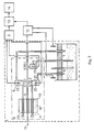
- FIG. 2 shows a measuring arrangement according to the invention of a more complicated structure, which is provided with two liquid switches and which is suitable for automatic error compensation in the Na + ion concentration determination.
- the measuring cell 1 is connected to the electronic signal processing unit 2 and the control unit 12.
- the measuring cell 1 is in the measuring chain 6 with the sample solution 15, with the sensing element 3 and with the sample-side reference electrode 4 in contact.
- An integrated sensor 19 of the measuring chain 6 also contains the already mentioned sample-side sensor element 3, as well as a first and second standard-side sensor element that is galvanically connected to the sensor via the electrolyte 18.
- the first standard-side sensing element 10 and the first standard-side reference electrode 9 are galvanically connected to one another via the first standard solution 17.
- the second standard-side sensing element 11 and the second standard-side reference electrode 20 are in galvanic connection with one another via the second standard solution 21.
- the measuring cell 1 contains the liquid switch 7, which is galvanically connected to the liquid spaces of the sample-side electrode 4 and the first standard-side reference electrode 9 via the liquid.
- a second liquid switch 8 is provided, which is galvanically connected to the liquid spaces of the sample-side electrode 4 and the second standard-side reference electrode 20 via the liquid.
- the measuring cell 1 is connected to the electronic signal processing unit 2 via the sample-side electrode, the first standard-side electrode 9 and the second standard-side reference electrode 20 and to the control unit 12 via the first and second liquid switches 7 and 8.
- the electronic signal processing unit 2 and the control unit 12 are connected to the computing and display unit 14 via the error-compensating unit 13.
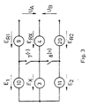
- FIG. 3 shows the simplified equivalent circuit diagram of the measuring cell 1 of an automatic error-compensating device according to FIG. 2 measuring the Na + ion concentration, which is equipped with two liquid switches and is somewhat more complicated than the device according to FIG. 1.
- the measuring chain 6 is designed with lead electrodes in the measuring cell 1 of the measuring device. These are the sample-side electrode 4, the first standard-side electrode 9 and the second standard-side reference electrode 20. In addition to the reference electrodes mentioned, the measuring chain 6 also contains a so-called integrated sensor 19.
- the value obtained in this way is practically independent of the standard potentials between the sensing elements 3, 10 and 11 and of the response function steepness and also of the measurement errors resulting from their changes. However, the calculated value still depends on the reference potentials measured at the reference electrodes 4, 9 and 20, and also on their instabilities.
- the resulting measurement errors can be eliminated by using the first and second liquid switches 7 and 8. In its closed state, the first liquid switch 7 short-circuits the two interfaces of the sample-side and standard-side sensing elements 3 and 10, and enables a direct measurement of the resulting electrode potentials that appear on the sample-side and standard-side reference electrodes 4 and 9.
- the second liquid switch 8 short-circuits the interfaces of the sample-side and the second standard-side sensing elements 3 and 11 in the switched-on state, whereby the direct measurement of those electrode potentials that occur on the sample-side and the second standard-side reference electrodes 4 and 20 is possible.
- the electronic signal processing unit 2 continuously measures the two voltages U A and U e which occur in relation to the reference electrode 4 on the sample side at the standard reference electrodes 9 and 20.
- the Control unit 12 closes at predetermined time intervals, e.g. B. at the end of each measurement, alternately the first liquid switch 7 and then the second liquid switch 8 short.
- the error compensation unit 13 forms the voltage differences, which are measured by the electronic signal processing unit, per pair when the liquid switches 7 and 8 are switched on and off.
Landscapes
- Chemical & Material Sciences (AREA)
- Life Sciences & Earth Sciences (AREA)
- Health & Medical Sciences (AREA)
- General Physics & Mathematics (AREA)
- Pathology (AREA)
- Electrochemistry (AREA)
- Physics & Mathematics (AREA)
- Analytical Chemistry (AREA)
- Biochemistry (AREA)
- General Health & Medical Sciences (AREA)
- Molecular Biology (AREA)
- Immunology (AREA)
- Chemical Kinetics & Catalysis (AREA)
- Investigating Or Analyzing Materials By The Use Of Electric Means (AREA)
- Analysing Materials By The Use Of Radiation (AREA)
- Investigating Or Analysing Biological Materials (AREA)
- Automatic Analysis And Handling Materials Therefor (AREA)
- Steroid Compounds (AREA)
- Disintegrating Or Milling (AREA)
- Adhesives Or Adhesive Processes (AREA)
- Developing Agents For Electrophotography (AREA)
Priority Applications (1)
| Application Number | Priority Date | Filing Date | Title |
|---|---|---|---|
| AT82102520T ATE39025T1 (de) | 1981-03-26 | 1982-03-25 | Fehlerkompensierendes elektroanalytisches messverfahren, sowie messgeraet zur durchfuehrung des messverfahrens. |
Applications Claiming Priority (2)
| Application Number | Priority Date | Filing Date | Title |
|---|---|---|---|
| HU8181758A HU180405B (en) | 1981-03-26 | 1981-03-26 | Device for individual feeding winding units to winding machines |
| HU75881 | 1981-03-26 |
Publications (3)
| Publication Number | Publication Date |
|---|---|
| EP0062250A2 EP0062250A2 (de) | 1982-10-13 |
| EP0062250A3 EP0062250A3 (en) | 1985-04-17 |
| EP0062250B1 true EP0062250B1 (de) | 1988-11-30 |
Family
ID=10951195
Family Applications (1)
| Application Number | Title | Priority Date | Filing Date |
|---|---|---|---|
| EP82102520A Expired EP0062250B1 (de) | 1981-03-26 | 1982-03-25 | Fehlerkompensierendes elektroanalytisches Messverfahren, sowie Messgerät zur Durchführung des Messverfahrens |
Country Status (11)
| Country | Link |
|---|---|
| US (1) | US4430164A (cs) |
| EP (1) | EP0062250B1 (cs) |
| JP (1) | JPS57169669A (cs) |
| AT (1) | ATE39025T1 (cs) |
| BR (1) | BR8201567A (cs) |
| CS (1) | CS236777B2 (cs) |
| DD (1) | DD202345A5 (cs) |
| DE (1) | DE3279251D1 (cs) |
| DK (1) | DK93082A (cs) |
| HU (1) | HU180405B (cs) |
| PL (1) | PL134572B1 (cs) |
Families Citing this family (4)
| Publication number | Priority date | Publication date | Assignee | Title |
|---|---|---|---|---|
| DE3668991D1 (de) * | 1986-04-15 | 1990-03-15 | Yokagawa Electrofact B V | Vorrichtung zur pruefung der vollstaendigkeit einer elektrode in einem potentiometrischen elektrodensystem. |
| US9128045B2 (en) * | 2007-04-12 | 2015-09-08 | Mocon, Inc. | Electrochemical sensor with zero calibration feature and method of calibrating |
| CN107462782A (zh) * | 2016-06-02 | 2017-12-12 | 镇江腾龙智能科技有限公司 | 游动电位在线测量仪器绝对与相对检测信号设计 |
| CN109735883B (zh) | 2019-02-20 | 2021-02-12 | 江苏大学 | 一种激光辅助柔性随动式工具电极微细电沉积的装置及方法 |
Family Cites Families (6)
| Publication number | Priority date | Publication date | Assignee | Title |
|---|---|---|---|---|
| JPS529490A (en) * | 1975-07-14 | 1977-01-25 | Horiba Ltd | Liquid penetrating portion of reference electrode |
| DE2612915C2 (de) | 1976-03-26 | 1986-05-28 | Robert Bosch Gmbh, 7000 Stuttgart | Verfahren und Vorrichtung einer unter der Führung einer λ-Sonde arbeitenden Regelung |
| JPS5459199A (en) * | 1977-10-20 | 1979-05-12 | Olympus Optical Co Ltd | Ion concentration measuring apparatus |
| JPS54119787A (en) * | 1978-03-10 | 1979-09-17 | Olympus Optical Co | Ionic electrode measuring method and its device |
| US4189367A (en) | 1978-10-19 | 1980-02-19 | Leeds & Northrup Company | Method for testing ion selective electrodes in continuous measuring systems |
| HU181287B (en) * | 1981-03-13 | 1983-06-28 | Radelkis Electrokemiai | Electroanalytic measuring arrangement |
-
1981
- 1981-03-26 HU HU8181758A patent/HU180405B/hu not_active IP Right Cessation
-
1982
- 1982-03-01 US US06/353,290 patent/US4430164A/en not_active Expired - Fee Related
- 1982-03-03 DK DK93082A patent/DK93082A/da not_active Application Discontinuation
- 1982-03-15 DD DD82238161A patent/DD202345A5/de not_active IP Right Cessation
- 1982-03-18 JP JP57043679A patent/JPS57169669A/ja active Pending
- 1982-03-18 CS CS821844A patent/CS236777B2/cs unknown
- 1982-03-22 BR BR8201567A patent/BR8201567A/pt unknown
- 1982-03-24 PL PL1982235609A patent/PL134572B1/pl unknown
- 1982-03-25 EP EP82102520A patent/EP0062250B1/de not_active Expired
- 1982-03-25 AT AT82102520T patent/ATE39025T1/de not_active IP Right Cessation
- 1982-03-25 DE DE8282102520T patent/DE3279251D1/de not_active Expired
Also Published As
| Publication number | Publication date |
|---|---|
| JPS57169669A (en) | 1982-10-19 |
| ATE39025T1 (de) | 1988-12-15 |
| US4430164A (en) | 1984-02-07 |
| DD202345A5 (de) | 1983-09-07 |
| BR8201567A (pt) | 1983-02-08 |
| CS236777B2 (en) | 1985-05-15 |
| DE3279251D1 (en) | 1989-01-05 |
| HU180405B (en) | 1983-03-28 |
| DK93082A (da) | 1982-09-27 |
| PL235609A1 (cs) | 1982-10-25 |
| PL134572B1 (en) | 1985-08-31 |
| EP0062250A3 (en) | 1985-04-17 |
| EP0062250A2 (de) | 1982-10-13 |
Similar Documents
| Publication | Publication Date | Title |
|---|---|---|
| EP0065202B1 (de) | Verfahren zur Messung von Ionenkonzentrationen | |
| DE3445164C2 (cs) | ||
| DE60219060T2 (de) | Konzentrationsmessverfahren und konzentrationsmessinstrument für spezifische komponenten | |
| DE69434042T2 (de) | Steckbarer speicherbaustein | |
| DE2501812C2 (de) | Meßanordnung zur Messung der Leitfähigkeit eines Elektrolyten | |
| DE3844386C2 (cs) | ||
| DE2224703A1 (de) | Elektrochemische Meßeinrichtung | |
| DE102013109105A1 (de) | Messanordnung | |
| DE3226552C2 (cs) | ||
| DE3030664A1 (de) | Verfahren zur bestimmung der stromausbeute bei galvanischen baedern | |
| DE68927566T2 (de) | Temperaturausgleich für potentiometrisch arbeitende ISFETs | |
| DE3033730C2 (de) | Vorrichtung zum Feststellen chemischer Substanzen | |
| DE102012101254A1 (de) | Messanordnung und Verfahren zur Erfassung einer Analytkonzentration in einem Messmedium | |
| DE3136248C2 (de) | Verfahren zur Zustandsprüfung von polarographischen Meßelektroden sowie Einrichtung zur Durchführung des Verfahrens | |
| DE1915170C3 (de) | Verfahren und Anordnung zur Bestimmung der Wanderungsgeschwindigkeit und/oder Konzentration von Zonen bei der Elektrophorese | |
| EP0062250B1 (de) | Fehlerkompensierendes elektroanalytisches Messverfahren, sowie Messgerät zur Durchführung des Messverfahrens | |
| DE2252442C3 (de) | Korrosionsgeschwindigkeitsmesser | |
| EP0060533B1 (de) | Elektroanalytische Messanordnung | |
| DE2508785A1 (de) | Vorrichtung zur elektrophoretischen analyse von elektrisch geladenen teilchen | |
| EP0262582B1 (de) | Verfahren zur Bestimmung des Konzentrationsverhältnisses von Lithiumionen zu Natriumionen und Vorrichtung zur Durchführung dieses Verfahrens | |
| DE4228609C1 (de) | Vorrichtung zur Messung von Ionenkonzentrationen in Lösungen | |
| EP0247535A2 (de) | Referenzelektrode für die Ionenaktivitätsmessung, insbesondere für die pH-Wertmessung | |
| DE4029321C2 (cs) | ||
| DE2648538C2 (de) | Verfahren zur automatisch geregelten Konstanthaltung der Zusammensetzung von Bädern und Vorrichtung zur Durchfährung des Verfahrens | |
| DE3216791A1 (de) | Verfahren und anordnung zur messung von ionenkonzentrationen |
Legal Events
| Date | Code | Title | Description |
|---|---|---|---|
| PUAI | Public reference made under article 153(3) epc to a published international application that has entered the european phase |
Free format text: ORIGINAL CODE: 0009012 |
|
| AK | Designated contracting states |
Designated state(s): AT CH DE FR GB SE |
|
| PUAL | Search report despatched |
Free format text: ORIGINAL CODE: 0009013 |
|
| AK | Designated contracting states |
Designated state(s): AT CH DE FR GB LI SE |
|
| 17P | Request for examination filed |
Effective date: 19850509 |
|
| 17Q | First examination report despatched |
Effective date: 19861113 |
|
| GRAA | (expected) grant |
Free format text: ORIGINAL CODE: 0009210 |
|
| AK | Designated contracting states |
Kind code of ref document: B1 Designated state(s): AT CH DE FR GB LI SE |
|
| REF | Corresponds to: |
Ref document number: 39025 Country of ref document: AT Date of ref document: 19881215 Kind code of ref document: T |
|
| GBT | Gb: translation of ep patent filed (gb section 77(6)(a)/1977) | ||
| REF | Corresponds to: |
Ref document number: 3279251 Country of ref document: DE Date of ref document: 19890105 |
|
| ET | Fr: translation filed | ||
| PGFP | Annual fee paid to national office [announced via postgrant information from national office to epo] |
Ref country code: AT Payment date: 19890310 Year of fee payment: 8 |
|
| PGFP | Annual fee paid to national office [announced via postgrant information from national office to epo] |
Ref country code: SE Payment date: 19890317 Year of fee payment: 8 |
|
| PGFP | Annual fee paid to national office [announced via postgrant information from national office to epo] |
Ref country code: FR Payment date: 19890323 Year of fee payment: 8 |
|
| PGFP | Annual fee paid to national office [announced via postgrant information from national office to epo] |
Ref country code: GB Payment date: 19890331 Year of fee payment: 8 Ref country code: CH Payment date: 19890331 Year of fee payment: 8 |
|
| PGFP | Annual fee paid to national office [announced via postgrant information from national office to epo] |
Ref country code: DE Payment date: 19890413 Year of fee payment: 8 |
|
| PLBE | No opposition filed within time limit |
Free format text: ORIGINAL CODE: 0009261 |
|
| STAA | Information on the status of an ep patent application or granted ep patent |
Free format text: STATUS: NO OPPOSITION FILED WITHIN TIME LIMIT |
|
| 26N | No opposition filed | ||
| PG25 | Lapsed in a contracting state [announced via postgrant information from national office to epo] |
Ref country code: GB Effective date: 19900325 Ref country code: AT Effective date: 19900325 |
|
| PG25 | Lapsed in a contracting state [announced via postgrant information from national office to epo] |
Ref country code: SE Effective date: 19900326 |
|
| PG25 | Lapsed in a contracting state [announced via postgrant information from national office to epo] |
Ref country code: LI Effective date: 19900331 Ref country code: CH Effective date: 19900331 |
|
| GBPC | Gb: european patent ceased through non-payment of renewal fee | ||
| PG25 | Lapsed in a contracting state [announced via postgrant information from national office to epo] |
Ref country code: FR Effective date: 19901130 |
|
| REG | Reference to a national code |
Ref country code: CH Ref legal event code: PL |
|
| PG25 | Lapsed in a contracting state [announced via postgrant information from national office to epo] |
Ref country code: DE Effective date: 19901201 |
|
| REG | Reference to a national code |
Ref country code: FR Ref legal event code: ST |
|
| EUG | Se: european patent has lapsed |
Ref document number: 82102520.2 Effective date: 19910110 |