EP0061945B1 - Gleitstuhl und dessen Benutzung in einem Eisenbahnweichensystem - Google Patents
Gleitstuhl und dessen Benutzung in einem Eisenbahnweichensystem Download PDFInfo
- Publication number
- EP0061945B1 EP0061945B1 EP82400339A EP82400339A EP0061945B1 EP 0061945 B1 EP0061945 B1 EP 0061945B1 EP 82400339 A EP82400339 A EP 82400339A EP 82400339 A EP82400339 A EP 82400339A EP 0061945 B1 EP0061945 B1 EP 0061945B1
- Authority
- EP
- European Patent Office
- Prior art keywords
- tongue
- slide plate
- needle
- counter
- ceramic material
- Prior art date
- Legal status (The legal status is an assumption and is not a legal conclusion. Google has not performed a legal analysis and makes no representation as to the accuracy of the status listed.)
- Expired
Links
- 229910010293 ceramic material Inorganic materials 0.000 claims abstract description 21
- PNEYBMLMFCGWSK-UHFFFAOYSA-N aluminium oxide Inorganic materials [O-2].[O-2].[O-2].[Al+3].[Al+3] PNEYBMLMFCGWSK-UHFFFAOYSA-N 0.000 claims description 7
- 229910052751 metal Inorganic materials 0.000 claims description 2
- 239000002184 metal Substances 0.000 claims description 2
- 150000004767 nitrides Chemical class 0.000 claims description 2
- 210000002105 tongue Anatomy 0.000 claims 5
- 239000000919 ceramic Substances 0.000 description 17
- 239000000853 adhesive Substances 0.000 description 7
- 230000001070 adhesive effect Effects 0.000 description 7
- VYPSYNLAJGMNEJ-UHFFFAOYSA-N Silicium dioxide Chemical compound O=[Si]=O VYPSYNLAJGMNEJ-UHFFFAOYSA-N 0.000 description 6
- 230000006835 compression Effects 0.000 description 6
- 238000007906 compression Methods 0.000 description 6
- 238000005461 lubrication Methods 0.000 description 5
- 239000000463 material Substances 0.000 description 5
- 239000004033 plastic Substances 0.000 description 5
- 229920003023 plastic Polymers 0.000 description 5
- 229910000831 Steel Inorganic materials 0.000 description 4
- 239000003292 glue Substances 0.000 description 4
- 239000004519 grease Substances 0.000 description 4
- 230000001050 lubricating effect Effects 0.000 description 4
- 239000004576 sand Substances 0.000 description 4
- 239000010959 steel Substances 0.000 description 4
- 239000004677 Nylon Substances 0.000 description 3
- 238000004026 adhesive bonding Methods 0.000 description 3
- 239000000428 dust Substances 0.000 description 3
- 239000003822 epoxy resin Substances 0.000 description 3
- 239000000314 lubricant Substances 0.000 description 3
- 229920001778 nylon Polymers 0.000 description 3
- 229920000647 polyepoxide Polymers 0.000 description 3
- 229910001018 Cast iron Inorganic materials 0.000 description 2
- 238000004140 cleaning Methods 0.000 description 2
- 230000006866 deterioration Effects 0.000 description 2
- 230000000737 periodic effect Effects 0.000 description 2
- 229910010271 silicon carbide Inorganic materials 0.000 description 2
- 235000001674 Agaricus brunnescens Nutrition 0.000 description 1
- 229910052580 B4C Inorganic materials 0.000 description 1
- 229910052582 BN Inorganic materials 0.000 description 1
- PZNSFCLAULLKQX-UHFFFAOYSA-N Boron nitride Chemical compound N#B PZNSFCLAULLKQX-UHFFFAOYSA-N 0.000 description 1
- 239000004642 Polyimide Substances 0.000 description 1
- 229910052581 Si3N4 Inorganic materials 0.000 description 1
- 230000032683 aging Effects 0.000 description 1
- 238000005452 bending Methods 0.000 description 1
- INAHAJYZKVIDIZ-UHFFFAOYSA-N boron carbide Chemical compound B12B3B4C32B41 INAHAJYZKVIDIZ-UHFFFAOYSA-N 0.000 description 1
- 230000007797 corrosion Effects 0.000 description 1
- 238000005260 corrosion Methods 0.000 description 1
- 238000006073 displacement reaction Methods 0.000 description 1
- 229920006332 epoxy adhesive Polymers 0.000 description 1
- 230000003628 erosive effect Effects 0.000 description 1
- LNEPOXFFQSENCJ-UHFFFAOYSA-N haloperidol Chemical compound C1CC(O)(C=2C=CC(Cl)=CC=2)CCN1CCCC(=O)C1=CC=C(F)C=C1 LNEPOXFFQSENCJ-UHFFFAOYSA-N 0.000 description 1
- 238000010438 heat treatment Methods 0.000 description 1
- 229910052500 inorganic mineral Inorganic materials 0.000 description 1
- 238000003754 machining Methods 0.000 description 1
- 238000012423 maintenance Methods 0.000 description 1
- 150000001247 metal acetylides Chemical class 0.000 description 1
- 239000011707 mineral Substances 0.000 description 1
- 230000004048 modification Effects 0.000 description 1
- 238000012986 modification Methods 0.000 description 1
- RVTZCBVAJQQJTK-UHFFFAOYSA-N oxygen(2-);zirconium(4+) Chemical compound [O-2].[O-2].[Zr+4] RVTZCBVAJQQJTK-UHFFFAOYSA-N 0.000 description 1
- 239000002245 particle Substances 0.000 description 1
- 229920001721 polyimide Polymers 0.000 description 1
- 239000000843 powder Substances 0.000 description 1
- 238000003825 pressing Methods 0.000 description 1
- 229910001404 rare earth metal oxide Inorganic materials 0.000 description 1
- 230000029058 respiratory gaseous exchange Effects 0.000 description 1
- HBMJWWWQQXIZIP-UHFFFAOYSA-N silicon carbide Chemical compound [Si+]#[C-] HBMJWWWQQXIZIP-UHFFFAOYSA-N 0.000 description 1
- 239000000377 silicon dioxide Substances 0.000 description 1
- HQVNEWCFYHHQES-UHFFFAOYSA-N silicon nitride Chemical compound N12[Si]34N5[Si]62N3[Si]51N64 HQVNEWCFYHHQES-UHFFFAOYSA-N 0.000 description 1
- 238000003892 spreading Methods 0.000 description 1
- 239000004575 stone Substances 0.000 description 1
- 230000003313 weakening effect Effects 0.000 description 1
- 229910001928 zirconium oxide Inorganic materials 0.000 description 1
Images
Classifications
-
- E—FIXED CONSTRUCTIONS
- E01—CONSTRUCTION OF ROADS, RAILWAYS, OR BRIDGES
- E01B—PERMANENT WAY; PERMANENT-WAY TOOLS; MACHINES FOR MAKING RAILWAYS OF ALL KINDS
- E01B7/00—Switches; Crossings
- E01B7/02—Tongues; Associated constructions
-
- E—FIXED CONSTRUCTIONS
- E01—CONSTRUCTION OF ROADS, RAILWAYS, OR BRIDGES
- E01B—PERMANENT WAY; PERMANENT-WAY TOOLS; MACHINES FOR MAKING RAILWAYS OF ALL KINDS
- E01B2202/00—Characteristics of moving parts of rail systems, e.g. switches, special frogs, tongues
- E01B2202/02—Nature of the movement
- E01B2202/021—Turning or tilting or elastically bending
- E01B2202/024—Turning or tilting or elastically bending about vertical axis
-
- E—FIXED CONSTRUCTIONS
- E01—CONSTRUCTION OF ROADS, RAILWAYS, OR BRIDGES
- E01B—PERMANENT WAY; PERMANENT-WAY TOOLS; MACHINES FOR MAKING RAILWAYS OF ALL KINDS
- E01B2202/00—Characteristics of moving parts of rail systems, e.g. switches, special frogs, tongues
- E01B2202/04—Nature of the support or bearing
- E01B2202/042—Sliding
-
- E—FIXED CONSTRUCTIONS
- E01—CONSTRUCTION OF ROADS, RAILWAYS, OR BRIDGES
- E01B—PERMANENT WAY; PERMANENT-WAY TOOLS; MACHINES FOR MAKING RAILWAYS OF ALL KINDS
- E01B2202/00—Characteristics of moving parts of rail systems, e.g. switches, special frogs, tongues
- E01B2202/04—Nature of the support or bearing
- E01B2202/06—Use of friction-reducing surfaces
Definitions
- the present invention relates to a sliding pad, usable in railroad switching systems.
- Railroad switch systems generally include a straight counter needle associated with a curved needle and a straight needle associated with a curved counter needle, which can be positioned between them in two different ways to ensure or not the connection with a track of deviation.
- the needles are made of parts planed in rails of special profiles which are supported by sliding bearings and generally made of cast iron fixed on the support sleepers of the railway.
- the upper surface of the bearings is lubricated with suitable greases.
- the pads currently used have the disadvantage of not having a sufficient slip coefficient and it is therefore necessary to cover them with a film of lubricating grease.
- This requires regular lubrication work which is a source of expenditure, not only for those who carry out the lubrication operation which is to be renewed at least every 15 days, but also for those who are responsible for security.
- this lubrication work on the track involves the risk of accidents for the personnel assigned to maintenance, in particular on the railways where many trains run.
- the film of lubricating grease present on the surface of the bearing can retain the dust which comes from the track, and when dust as hard as sand accumulates in the film of lubricating grease, this leads to a deterioration of the system. referral.
- the present invention specifically relates to a sliding bearing usable in particular in a railroad switching system, which avoids the aforementioned drawbacks.
- the sliding pad according to the invention is characterized in that it comprises a sliding surface made of ceramic material.
- this pad comprises a support provided with a recess and a piece of ceramic material fixed by gluing in said recess so as to constitute said sliding surface.
- this pad comprises a support provided with a recess and a plurality of pieces of ceramic material fixed by gluing in said recess so as to constitute said sliding surface.
- the pieces of ceramic material have rounded edges to facilitate sliding at the junction between two pieces.
- the ceramic material is very important to fix the pieces of ceramic material by bonding to the support because this allows them to work in compression and to resist the loads which circulate on the switch.
- ceramic materials are more resistant to compression than to bending and under the conditions of use of the bearing, the ceramic parts are stressed by these two constraints.
- the adhesive joint provided between the piece of ceramic material and the support, the loads are distributed over the entire surface and the ceramic can work in compression.
- this glue joint is protected against weathering and irradiation by the ceramic part and therefore it does not degrade like plastic pads.
- the adhesives used are generally based on epoxy resins, but it is also possible to use adhesives based on polyimides which are resistant to heat.
- Epoxy adhesives filled with mineral powders such as alumina or silica sand can be used in particular.
- mineral powders such as alumina or silica sand
- the adhesive referenced 2850 GT sold by Emerson and Cuming which has a compressive strength of 70 to 130 MPa and a shear strength of 20 to 40 MPa.
- the ceramic material used must have a low coefficient of sliding compared to steel and a hardness significantly higher than that of steel or cast iron so as not to allow the inclusion of materials such than sand or crushed stone which would deteriorate the sliding surface of the bearing by damaging its polish.
- the ceramic material must withstand the atmospheric corrosion and momentary compression due to the pressing of each axle and corresponding to daily loads which may exceed 40,000 tonnes, for a long period of use, for example of the order of 10 years.
- Examples of materials which can be used include sintered oxides such as alumina, zirconium oxide and rare earth oxides, nitrides such as boron nitride and silicon nitride , and carbides such as silicon carbide and boron carbide.
- high hardness alumina is used which resists compression well.
- the bearings must withstand very high pressures which can go up to 150 bars in the thinned zone of the needles when the latter are loaded at 10 tonnes per wheel.
- the ceramics which can be used the characteristics of which are given in the attached table, alumina 99.7% of A1 2 0 3 is preferred. Indeed, we prefer to use the least porous ceramics to avoid fouling and "breathing" of the adhesive joint, which causes its aging, and to have a good coefficient of friction.
- the ceramic with the best compression performance and the best flexural strength is chosen.
- the invention also relates to a railroad switching system comprising a straight counter-needle associated with a curved needle, a curved counter-needle associated with a straight needle, a first series of sliding bearings for supporting the counter- straight needle and curved needle and a second series of sliding bearings for supporting the straight needle and curved counter-needle, characterized in that the sliding surfaces of the bearings of the first and second series are made of material ceramic, said surfaces having dimensions such that the needles are always supported on said surfaces during the operation of the switch.
- each bearing of the first or of the second series comprises a metal support on which is fixed the straight counter-needle or the curved counter-needle, said support being provided with a recess in which are fixed by gluing a plurality of parts made of ceramic material arranged so as to form the sliding surface of said pad.
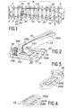
- FIG 1 there is shown a railway and the switch system A associated therewith.
- the railroad consists of two rails 1 and 3 which are fixed on sleepers 5 by means of fastening devices provided with lag screws 7.
- the switch system A which follows comprises a counter -right needle 11, a curved needle 13, a curved counter-needle 15 and a straight needle 17.
- the right and curved counter-needles are fixed respectively on a first series and a second series of bearings sliding 19, themselves fixed by lag screws on the sleepers 5 of the railway.
- the needles 13 and 17 are supported respectively by the first and the second series of sliding bearings 19, and they can be moved between a first position in which the needle 13 is in contact with the counter-needle 11 while the needle 17 is moved away from the counter-needle 15, at a second position in which the straight needle 17 is in contact with the curved counter-needle 15 while the needle 13 is moved away from the right counter-needle 11.
- This displacement is obtained at by means of an operating device possibly comprising a motor 21 which actuates the operating rod 23 associated with the spacing rod 25.
- each pair of rails which constitutes the main track I and the deviation I1 is again fixed to the crosspieces 5 by lag screw devices 7.
- each sliding pad 19 supports a counter needle and the needle associated with it, for example the right counter needle 11 and the curved needle 13.
- the counter needle 11 is rendered secured to the sliding pad by a suitable device such as 31, while the needle 13 can move on the pad 19 between two extreme positions.
- the needle 11 comprises, like the rail 1, an upper part called the mushroom 11 a which supports the contact of the wheel, a thinned middle part 11 b which constitutes the core, and an enlarged lower part 11c which constitutes the pad used for the fixing the rail on the crosspieces.
- the needle comprises an upper part 13a whose thickness increases progressively and regularly from its point of contact with the counter-needle which is associated with it, a middle part 13b and a lower part in the form of a shoe 13c.
- the sliding pads 19 were made of steel and provided with films of lubricating grease on their surface to promote the sliding of needles such as 13 on the pads 19.
- the film of lubricant could retain dust, in particular sand, after a certain period of operation a deterioration of the upper surface of the pad and / or of the sole of the needle was obtained, which could lead to seizure and immobilization of the referral system.
- each sliding pad 19 comprises a sliding surface 20 made of ceramic material, for example of high hardness alumina.
- it is preferred to avoid a modification of the movable part of the switch because the realization of recess to insert the ceramic poses certain problems to preserve the profile and the mechanical properties of the moving parts of the switch rails. Indeed, the machining operations risk leading to weakening of the needles by notch phenomena with propagation of cracks.
- the sliding bearing 19 shown in Figure 2 can be obtained as follows.
- a recess is formed at the top of a pad 19 made of steel, and then there are plastic threads, for example nylon threads, at the bottom of the recess.
- a piece of ceramic material for example of sintered alumina having a shape which corresponds substantially to that of the recess, is prepared separately, then a certain quantity of glue is introduced, constituted for example by an epoxy resin at the center of the recess, and the ceramic part is placed in the recess by compressing it to ensure its bonding by means of the epoxy resin.
- nylon threads are intended to promote the spreading of the adhesive over the entire surface of the recess, which thus ensures good bonding of the ceramic part and to obtain an adhesive joint on the entire lower surface of the ceramic part.
- the nylon threads are generally 5/10 mm thick.
- this also includes a support 19a of a suitable shape for fixing the counter-needle, and this support 19a is provided with a recess in which are fixed two ceramic plates 20a and 20b arranged in such a way that the junction between the plates extends in a direction parallel to the direction of movement of the needle between its two extreme positions. In this way it avoids the problems of sliding of the needle, which could arise at the junction between two plates.
- the ceramic plates can be arranged differently, for example with junctions between plates extending in directions perpendicular to the direction of movement of the needle.
- plates 20a, 20b ... whose edges are rounded at the junction between successive plates in order to avoid the problems of sliding which could arise due to a difference. thick between two consecutive pads.
- the pads include several ceramic pads, they can be made in the same way as the pads with a single pad by assembling the pads in the recess provided with plastic wires and glue, and then compressing the assembly to that the sliding surface makes a single plane.
Landscapes
- Engineering & Computer Science (AREA)
- Mechanical Engineering (AREA)
- Architecture (AREA)
- Civil Engineering (AREA)
- Structural Engineering (AREA)
- Sliding-Contact Bearings (AREA)
- Slide Switches (AREA)
- Portable Nailing Machines And Staplers (AREA)
- Infusion, Injection, And Reservoir Apparatuses (AREA)
- Details Of Garments (AREA)
- Railway Tracks (AREA)
Claims (8)
Priority Applications (1)
| Application Number | Priority Date | Filing Date | Title |
|---|---|---|---|
| AT82400339T ATE9497T1 (de) | 1981-03-03 | 1982-02-26 | Gleitstuhl und dessen benutzung in einem eisenbahnweichensystem. |
Applications Claiming Priority (2)
| Application Number | Priority Date | Filing Date | Title |
|---|---|---|---|
| FR8104234A FR2501253A1 (fr) | 1981-03-03 | 1981-03-03 | Coussinet de glissement et son utilisation dans un systeme d'aiguillage de voies ferrees |
| FR8104234 | 1981-03-03 |
Publications (2)
| Publication Number | Publication Date |
|---|---|
| EP0061945A1 EP0061945A1 (de) | 1982-10-06 |
| EP0061945B1 true EP0061945B1 (de) | 1984-09-19 |
Family
ID=9255822
Family Applications (1)
| Application Number | Title | Priority Date | Filing Date |
|---|---|---|---|
| EP82400339A Expired EP0061945B1 (de) | 1981-03-03 | 1982-02-26 | Gleitstuhl und dessen Benutzung in einem Eisenbahnweichensystem |
Country Status (6)
| Country | Link |
|---|---|
| EP (1) | EP0061945B1 (de) |
| JP (1) | JPS5813801A (de) |
| AT (1) | ATE9497T1 (de) |
| DE (1) | DE3260759D1 (de) |
| ES (1) | ES8303582A1 (de) |
| FR (1) | FR2501253A1 (de) |
Cited By (1)
| Publication number | Priority date | Publication date | Assignee | Title |
|---|---|---|---|---|
| DE3709126A1 (de) * | 1987-03-23 | 1988-10-13 | Butzbacher Weichenbau Gmbh | Miteinander wechselwirkende gleisteile |
Families Citing this family (3)
| Publication number | Priority date | Publication date | Assignee | Title |
|---|---|---|---|---|
| JPH0421841Y2 (de) * | 1987-01-22 | 1992-05-19 | ||
| AT392497B (de) * | 1989-06-02 | 1991-04-10 | Voest Alpine Maschinenbau | Gleitstuhl, gleitplatte bzw. rippenplatte fuer schienenweichen oder -kreuzungen |
| FR2979925B1 (fr) * | 2011-09-08 | 2014-06-13 | Vossloh Cogifer | Dispositif de manœuvre ferroviaire sans graissage |
Family Cites Families (4)
| Publication number | Priority date | Publication date | Assignee | Title |
|---|---|---|---|---|
| FR2340403A1 (fr) * | 1976-02-09 | 1977-09-02 | Faigle Heinz | Appareil de voie pour vehicules ferroviaires |
| DE2631594C2 (de) * | 1976-07-14 | 1978-09-28 | Wilfried 7031 Nufringen Ensinger | Kunststoffgleitbelag für Schienenweichen |
| DE2656986A1 (de) * | 1976-12-16 | 1978-06-29 | Schwihag Gmbh | Anordnung zur verminderung der reibung und/oder abnuetzung zwischen den zueinander relativ beweglichen teilen in weichen und kreuzungen von gleisanlagen |
| FR2398841A1 (fr) * | 1977-07-27 | 1979-02-23 | Stecma | Coussinet pour lame d'aiguille des appareils de voie |
-
1981
- 1981-03-03 FR FR8104234A patent/FR2501253A1/fr active Granted
-
1982
- 1982-02-26 EP EP82400339A patent/EP0061945B1/de not_active Expired
- 1982-02-26 DE DE8282400339T patent/DE3260759D1/de not_active Expired
- 1982-02-26 AT AT82400339T patent/ATE9497T1/de not_active IP Right Cessation
- 1982-03-02 ES ES510059A patent/ES8303582A1/es not_active Expired
- 1982-03-03 JP JP57033743A patent/JPS5813801A/ja active Pending
Cited By (1)
| Publication number | Priority date | Publication date | Assignee | Title |
|---|---|---|---|---|
| DE3709126A1 (de) * | 1987-03-23 | 1988-10-13 | Butzbacher Weichenbau Gmbh | Miteinander wechselwirkende gleisteile |
Also Published As
| Publication number | Publication date |
|---|---|
| FR2501253A1 (fr) | 1982-09-10 |
| ES510059A0 (es) | 1983-02-01 |
| ES8303582A1 (es) | 1983-02-01 |
| FR2501253B1 (de) | 1983-09-16 |
| DE3260759D1 (en) | 1984-10-25 |
| ATE9497T1 (de) | 1984-10-15 |
| JPS5813801A (ja) | 1983-01-26 |
| EP0061945A1 (de) | 1982-10-06 |
Similar Documents
| Publication | Publication Date | Title |
|---|---|---|
| FR2504963A1 (fr) | Element de sol | |
| EP0061945B1 (de) | Gleitstuhl und dessen Benutzung in einem Eisenbahnweichensystem | |
| FR2688163A1 (fr) | Dispositif d'entretoisement pour les lames d'un train de scies et train de scies utilisant un tel dispositif. | |
| FR2595776A1 (fr) | Couronne d'orientation a roulement comprenant un dispositif d'etancheite | |
| FR2476707A1 (fr) | Eclissage electrique isole pour rails de voie ferree | |
| FR2520820A1 (fr) | Ensemble d'appui d'un element mobile soumis a une charge, et concasseur | |
| FR2788568A1 (fr) | Dispositif et procede de fixation d'un element metallique plan sur un support en beton | |
| FR3025813A1 (fr) | Selle de support de rail de voie ferree | |
| FR2994888A1 (fr) | Assemblage de deux pieces en materiau composite | |
| CA2572807C (fr) | Crapaud anticorrosif isolant et compose integralement d'une composition polymerique | |
| FR2640337A1 (fr) | Element en materiau de friction pour frein de vehicule | |
| EP1092110B1 (de) | Biegsame rohrleitung mit einer aufgewickelten, thermisch isolierenden bahn und wickelmaschine zur deren herstellung | |
| EP1495189B1 (de) | Bauwerksfuge | |
| EP4560075A1 (de) | Selbstbearbeitbare beton- und stahlbrücke ohne schwere wartung | |
| FR3004737A1 (fr) | Pont en beton | |
| EP0468120A1 (de) | Verbundstoffstruktur für Schwingungsdämpfung | |
| EP2962030A1 (de) | Vorrichtung zum schutz von mechanischen teilen | |
| FR3100210A1 (fr) | Patin pour freins a disque pour vehicules ferroviaires a moyenne/faible vitesse | |
| BE863519A (fr) | Substrat de ballast pour voies ferrees | |
| FR3040713A1 (fr) | Dispositif de maintien de traverses ferroviaires et voie ferree comprenant le dispositif | |
| EP3430203B1 (de) | Eisenbahnschienenträger | |
| FR2458627A1 (fr) | Ensemble de selle d'appui pour voie de chemin de fer | |
| FR2740152A1 (fr) | Joint routier renforce | |
| FR3109945A1 (fr) | Dispositif de fixation d’un rail | |
| WO2007006881A1 (fr) | Cale de restauration de la position d'un rail |
Legal Events
| Date | Code | Title | Description |
|---|---|---|---|
| PUAI | Public reference made under article 153(3) epc to a published international application that has entered the european phase |
Free format text: ORIGINAL CODE: 0009012 |
|
| AK | Designated contracting states |
Designated state(s): AT BE CH DE FR GB IT LI LU NL SE |
|
| RAP1 | Party data changed (applicant data changed or rights of an application transferred) |
Owner name: SOCIETE NATIONALE DES CHEMINS DE FER FRANCAIS Owner name: LAFARGE REFRACTAIRES SOCIETE ANONYME |
|
| 17P | Request for examination filed |
Effective date: 19830314 |
|
| ITF | It: translation for a ep patent filed | ||
| GRAA | (expected) grant |
Free format text: ORIGINAL CODE: 0009210 |
|
| AK | Designated contracting states |
Designated state(s): AT BE CH DE FR GB IT LI LU NL SE |
|
| REF | Corresponds to: |
Ref document number: 9497 Country of ref document: AT Date of ref document: 19841015 Kind code of ref document: T |
|
| REF | Corresponds to: |
Ref document number: 3260759 Country of ref document: DE Date of ref document: 19841025 |
|
| PG25 | Lapsed in a contracting state [announced via postgrant information from national office to epo] |
Ref country code: LU Free format text: LAPSE BECAUSE OF NON-PAYMENT OF DUE FEES Effective date: 19850228 |
|
| PLBE | No opposition filed within time limit |
Free format text: ORIGINAL CODE: 0009261 |
|
| STAA | Information on the status of an ep patent application or granted ep patent |
Free format text: STATUS: NO OPPOSITION FILED WITHIN TIME LIMIT |
|
| 26N | No opposition filed | ||
| PGFP | Annual fee paid to national office [announced via postgrant information from national office to epo] |
Ref country code: DE Payment date: 19900129 Year of fee payment: 9 |
|
| PGFP | Annual fee paid to national office [announced via postgrant information from national office to epo] |
Ref country code: SE Payment date: 19900130 Year of fee payment: 9 |
|
| PGFP | Annual fee paid to national office [announced via postgrant information from national office to epo] |
Ref country code: BE Payment date: 19900131 Year of fee payment: 9 |
|
| PGFP | Annual fee paid to national office [announced via postgrant information from national office to epo] |
Ref country code: LU Payment date: 19900205 Year of fee payment: 9 |
|
| PGFP | Annual fee paid to national office [announced via postgrant information from national office to epo] |
Ref country code: AT Payment date: 19900214 Year of fee payment: 9 |
|
| PGFP | Annual fee paid to national office [announced via postgrant information from national office to epo] |
Ref country code: CH Payment date: 19900216 Year of fee payment: 9 |
|
| PGFP | Annual fee paid to national office [announced via postgrant information from national office to epo] |
Ref country code: FR Payment date: 19900226 Year of fee payment: 9 |
|
| ITTA | It: last paid annual fee | ||
| PGFP | Annual fee paid to national office [announced via postgrant information from national office to epo] |
Ref country code: NL Payment date: 19900228 Year of fee payment: 9 Ref country code: GB Payment date: 19900228 Year of fee payment: 9 |
|
| PG25 | Lapsed in a contracting state [announced via postgrant information from national office to epo] |
Ref country code: GB Effective date: 19910226 Ref country code: AT Effective date: 19910226 |
|
| PG25 | Lapsed in a contracting state [announced via postgrant information from national office to epo] |
Ref country code: SE Effective date: 19910227 |
|
| PG25 | Lapsed in a contracting state [announced via postgrant information from national office to epo] |
Ref country code: LI Effective date: 19910228 Ref country code: CH Effective date: 19910228 Ref country code: BE Effective date: 19910228 |
|
| PG25 | Lapsed in a contracting state [announced via postgrant information from national office to epo] |
Ref country code: NL Effective date: 19910901 |
|
| NLV4 | Nl: lapsed or anulled due to non-payment of the annual fee | ||
| GBPC | Gb: european patent ceased through non-payment of renewal fee | ||
| PG25 | Lapsed in a contracting state [announced via postgrant information from national office to epo] |
Ref country code: FR Effective date: 19911031 |
|
| REG | Reference to a national code |
Ref country code: CH Ref legal event code: PL |
|
| PG25 | Lapsed in a contracting state [announced via postgrant information from national office to epo] |
Ref country code: DE Effective date: 19911101 |
|
| REG | Reference to a national code |
Ref country code: FR Ref legal event code: ST |
|
| EUG | Se: european patent has lapsed |
Ref document number: 82400339.6 Effective date: 19911008 |