EP0061515B1 - Russbläser - Google Patents
Russbläser Download PDFInfo
- Publication number
- EP0061515B1 EP0061515B1 EP81108159A EP81108159A EP0061515B1 EP 0061515 B1 EP0061515 B1 EP 0061515B1 EP 81108159 A EP81108159 A EP 81108159A EP 81108159 A EP81108159 A EP 81108159A EP 0061515 B1 EP0061515 B1 EP 0061515B1
- Authority
- EP
- European Patent Office
- Prior art keywords
- lance tube
- drive
- shaft
- clutch
- longitudinal
- Prior art date
- Legal status (The legal status is an assumption and is not a legal conclusion. Google has not performed a legal analysis and makes no representation as to the accuracy of the status listed.)
- Expired
Links
- 239000004071 soot Substances 0.000 title abstract description 9
- 230000008878 coupling Effects 0.000 claims description 6
- 238000010168 coupling process Methods 0.000 claims description 6
- 238000005859 coupling reaction Methods 0.000 claims description 6
- 230000005540 biological transmission Effects 0.000 claims description 4
- 238000007664 blowing Methods 0.000 description 9
- 238000010438 heat treatment Methods 0.000 description 3
- 238000000034 method Methods 0.000 description 3
- 238000004140 cleaning Methods 0.000 description 2
- 230000003111 delayed effect Effects 0.000 description 1
- 230000000694 effects Effects 0.000 description 1
- 230000003628 erosive effect Effects 0.000 description 1
- 230000000977 initiatory effect Effects 0.000 description 1
- 239000007788 liquid Substances 0.000 description 1
- 239000000463 material Substances 0.000 description 1
Images



Classifications
-
- F—MECHANICAL ENGINEERING; LIGHTING; HEATING; WEAPONS; BLASTING
- F28—HEAT EXCHANGE IN GENERAL
- F28G—CLEANING OF INTERNAL OR EXTERNAL SURFACES OF HEAT-EXCHANGE OR HEAT-TRANSFER CONDUITS, e.g. WATER TUBES OR BOILERS
- F28G15/00—Details
- F28G15/04—Feeding and driving arrangements, e.g. power operation
- F28G15/06—Automatic reversing devices
Definitions
- the invention relates to a soot blower with a lance tube, which is provided with a rotary drive and a longitudinal drive, which are connected to a motor and together with this and the lance tube are guided along a stationary carriage.
- Sootblowers of this type are used to remove deposits on hot surfaces, in particular on heating surfaces in boilers and apparatus, with the aid of a blowing jet at high speed.
- Sootblowers of this type have a lance tube as the blowing element, in which there are one or more nozzles through which a gaseous and / or liquid blowing medium emerges.
- the lance tube screws into the cleaning room, changes its direction of movement in the front end position and returns to the starting position. If, as usual, two opposing nozzles are installed at the tip of the lance tube, they perform a double helical movement, the spacing of the helical lines being half the selected feed per revolution.
- the drive elements for the longitudinal and rotary movement are mechanically firmly connected to one another, so that the same sequence of movements always results and the blowing jets always strike the same points on the heating surfaces to be cleaned with their core jet. This causes damage to the heating surface material due to erosion.
- the present invention aims to achieve the same goal as in DE-A 27 57 981, but with different means.
- the invention is therefore based on the object of further developing a soot blower of the type mentioned at the outset such that each blowing process can be started with a different nozzle position and this is achieved with simple means which are adapted to the rough operating conditions.
- This object is achieved in that a coupling is provided between the lance tube and the rotary drive or the longitudinal drive, which is controlled via a timing relay which is connected to a limit switch arranged at the end of the travel path of the lance tube.
- the clutch can be disengaged for a certain, short period of time. This stops one of the two movements of the lance tube - longitudinal movement or rotary movement - while the other movement continues. As a result, the backward movement of the lance tube always begins with a new position of the nozzles.
- the angular misalignment of the nozzle position caused by the disengagement of the clutch is somewhat different because of the always different friction characteristics of the clutch and the tolerance of the timing relay. As a result, statistically speaking, all possible nozzle positions can be set uniformly.
- the sootblower consists of a lance tube 1 which is guided over an inner tube 2.
- the inner tube 2 is provided with a blower valve 3, through which the lance tube 1 via the inner tube 2 a blowing medium, for. B. steam is supplied.
- the lance tube 1 carries at its front end a nozzle head 4, in which two opposing nozzles 5 are arranged.
- the lance tube 1 is shifted with simultaneous rotation in the longitudinal direction.
- the blowing jets emerging from the nozzles 5 describe a helical path.
- the lance tube 1 is moved by a motor 6, which drives a drive shaft 8 via a gear 7.
- the drive shaft 8 is connected to three output shafts.
- One output shaft is the rotary shaft 9, which is connected to the drive shaft 8 via a gear arrangement 10.
- a sprocket 11 is placed on the rotary shaft 9 and sets a second sprocket 13 in rotation via a chain 12, said sprocket being arranged on the lance tube 1.
- a worm 14, in which a worm wheel 15 engages, is arranged on the drive shaft 8.
- the worm wheel 15 drives two further output shafts, the feed shafts 16.
- a pinion 17 is rotatably arranged, which engages in a rack 18.
- the racks 18 are arranged on a stationary travel carrier 19.
- the lance tube 1 is connected to a blower carriage 20.
- the blower carriage 20 is provided with rollers 21 which are guided on rails 22 of the carriage 19.
- a limit switch 23 is provided at the end of the travel path of the lance tube 1. The limit switch 23 changes the direction of rotation of the motor 6 by a pulse, whereby the lance tube 1 is retracted after reaching its end position.
- the lance tube 1 is connected via a coupling either to the longitudinal drive or to the rotary drive.
- the clutch assigned to the longitudinal drive is formed by a slip clutch 24.
- This slip clutch 24 is a friction clutch, which represents the connection between the worm wheel 15 and the feed shaft 16.
- a plate spring 26 is provided between the slip clutch 24 and a shaft nut 25. By moving the shaft nut 25, which can be done from the outside, the maximum transmission torque of the slip clutch 24 can be adjusted.
- the transmission torque of the slip clutch 24 is set in the manner described so that it is less than the maximum torque of the motor 6.
- a freewheel 27 is provided between the worm wheel 15 and the feed shaft 16, which becomes effective when the lance tube 1 moves backward. While the freewheel 27 does not transmit any force during the forward movement of the lance tube 1, it ensures a non-positive connection between the feed shaft 16 and the worm wheel 15 during the backward movement the highest engine torque can be driven out of the hot cleaning rooms.
- a stop 28 interacts with the slip clutch 24 and is attached to the rails 22 at the end of the travel path of the lance tube 1. Furthermore, a timing relay is provided, which is connected to the limit switch 23 at the end of the route. The pulse of the limit switch 23; by which the reversal of the direction of motor rotation is controlled, effectively delayed by a time set on the time relay. If the blower carriage 20 moves against the stop 28, the slip clutch 24 slips and thus disengages, while the rotary movement of the lance tube 1 continues via the drive shaft 8, the gear arrangement 10, the rotary shaft 9 and the chain wheels 11, 13. The time during which the slip clutch 24 is kept disengaged in the manner described can be set on the timing relay. After completion of the forward movement of the lance tube 1 and before the initiation of the backward movement, the nozzles 5 are each offset by a certain angle in this way.
- a clutch 29 known per se is to be provided.
- This clutch is arranged between the rotary shaft 9 and the sprocket 11. It contains two clutch disks 30, 31 which are pressed against one another by springs 32.
- An electromagnet 33 is arranged within the coupling half receiving the springs 32. The force applied by the electromagnet 33 is directed counter to the force exerted by the springs 32 on the clutch disks 30, 31. When the electromagnet 33 is excited, the clutch disks 30, 31 are separated from one another against the spring force.
- the electromagnet 33 is provided with an electrical connection 34 which is connected to the timing relay of the limit switch 23.
Landscapes
- Engineering & Computer Science (AREA)
- Chemical & Material Sciences (AREA)
- Combustion & Propulsion (AREA)
- Mechanical Engineering (AREA)
- General Engineering & Computer Science (AREA)
- Incineration Of Waste (AREA)
- Power Steering Mechanism (AREA)
Description
- Die Erfindung betrifft einen Rußbläser mit einem Lanzenrohr, das mit einem Drehantrieb und einem Längsantrieb versehen ist, die mit einem Motor verbunden und zusammen mit diesem und dem Lanzenrohr an einem ortsfesten Fahrträger entlang geführt sind.
- Derartige Rußbläser dienen zum Ablösen von Ablagerungen an heißen Flächen, insbesondere an Heizflächen in Kesseln und Apparaten mit Hilfe eines Blasstrahles mit hoher Geschwindigkeit. Solche Rußbläser besitzen als Blaselement ein Lanzenrohr, in dem sich eine oder mehrere Düsen befinden, durch die ein gasförmiges und/oder flüssiges Blasmedium austritt. Das Lanzenrohr fährt schraubend in den Reinigungsraum ein, ändert in der vorderen Endstellung seine Bewegungsrichtung und kehrt in die Ausgangsstellung zurück. Wenn, wie gewöhnlich, an der Spitze des Lanzenrohres zwei gegenüberliegende Düsen eingebaut sind, führen diese eine doppelt-schraubenlinienförmige Bewegung aus, wobei die Abstände der Schraubenlinien die Hälfte des gewählten Vorschubes pro Umdrehung betragen. Die Antriebselemente für die Längs- und Drehbewegung sind mechanisch fest miteinander verbunden, so daß sich stets der gleiche Bewegungsablauf ergibt und die Blasstrahlen mit ihrem Kernstrahl immer die gleichen Stellen an den zu reinigenden Heizflächen treffen. Dadurch kommt es dort zu Schädigungen des Heizflächenmaterials durch Erosion.
- Um diese Nachteile zu vermeiden, ist es bekannt (DE-A 27 57 981), den Rußbläser so auszubilden, daß jeder Blasvorgang mit einer anderen Düsenstellung begonnen werden kann. Bei einem solchen Rußbläser sind zwischen der Abtriebswelle für die Längsbewegung und dem Schneckenrad zwei Freiläufe vorgesehen, die eine unterschiedliche Mitnahmerichtung aufweisen. In einem der Freiläufe ist ein Spiel in Drehrichtung der Abtriebswelle vorgesehen.
- Durch die vorliegende Erfindung soll das gleiche Ziel wie nach der DE-A 27 57 981, jedoch mit anderen Mitteln erreicht werden. Der Erfindung liegt daher die Aufgabe zugrunde, einen Rußbläser der eingangs genannten Art derart weiter zu entwickeln, daß jeder Blasvorgang mit einer anderen Düsenstellung begonnen werden kann und dies mit einfachen, den rauhen Betriebsbedingungen angepaßten Mitteln erreicht wird.
- Diese Aufgabe wird erfindungsgemäß dadurch gelöst, daß zwischen dem Lanzenrohr und dem Drehantrieb oder dem Längsantrieb eine Kupplung vorgesehen ist, die über ein Zeitrelais gesteuert ist, das mit einem am Ende des Fahrweges des Lanzenrohres angeordneten Endschalter verbunden ist.
- Bei dem erfindungsgemäßen Rußbläser kann die Kupplung für einen bestimmten, kurzen Zeitraum außer Eingriff gebracht werden. Dadurch wird eine der beiden Bewegungen des Lanzenrohres - Längsbewegung oder Drehbewegung - angehalten, während die jeweils andere Bewegung weiter ausgeführt wird. Dadurch beginnt die Rückwärtsbewegung des Lanzenrohres stets mit einer neuen Position der Düsen. Von besonderem Vorteil ist dabei der Umstand, daß der durch das Außereingriffbringen der Kupplung bedingte Winkelversatz der Düsenstellung auch bei gleicher Einstellung des Zeitrelais wegen der immer etwas unterschiedlichen Reibungscharakteristik der Kupplung und der Toleranz des Zeitrelais jeweils etwas unterschiedlich ausfällt. Dadurch ergibt sich, daß sich statistisch gesehen alle möglichen Düsenstellungen gleichmäßig einstellen lassen.
- Vorteilhafte Ausgestaltungen der Erfindung sind in den Unteransprüchen enthalten.
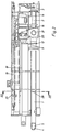
- Mehrere Ausführungsbeispiele sind in der Zeichnung dargestellt und werden im folgenden näher erläutert. Es zeigen :
- Figur 1 schematisch den Antrieb für einen Rußbläser,
- Figur 2 die Seitenansicht eines Rußbläsers,
- Figur 3 den Schnitt 111-111 nach Fig. 2,
- Figur 4 den Schnitt IV-IV nach Fig. 2 und
- Figur 5 in Längsschnitt eine für den Antrieb geeignete Schaltkupplung.
- Der Rußbläser besteht aus einem Lanzenrohr 1, das über ein Innenrohr 2 geführt ist. An seinem hinteren Ende ist das Innenrohr 2 mit einem Bläserventil 3 versehen, durch das dem Lanzenrohr 1 über das Innenrohr 2 ein Blasmedium, z. B. Wasserdampf, zugeführt wird. Das Lanzenrohr 1 trägt an seinem vorderen Ende einen Düsenkopf 4, in dem zwei einander gegenüberliegende Düsen 5 angeordnet sind. Das Lanzenrohr 1 wird unter gleichzeitiger Drehung in Längsrichtung verschoben. Dabei beschreiben die aus den Düsen 5 austretenden Blasstrahlen einen schraubenlinienförmigen Weg.
- Die Bewegung des Lanzenrohres 1 erfolgt durch einen Motor 6, der über ein Getriebe 7 eine Antriebswelle 8 antreibt. Die Antriebswelle 8 ist mit drei Abtriebswellen verbunden. Die eine Abtriebswelle ist die Drehwelle 9, die über eine Getriebeanordnung 10 mit der Antriebswelle 8 verbunden ist. Auf die Drehwelle 9 ist ein Kettenrad 11 aufgesetzt, das über eine Kette 12 ein zweites Kettenrad 13 in Drehung versetzt, das auf dem Lanzenrohr 1 angeordnet ist.
- Auf der Antriebswelle 8 ist eine Schnecke 14 angeordnet, in die ein Schneckenrad 15 eingreift. Das Schneckenrad 15 treibt zwei weitere Abtriebswellen, die Vorschubwellen 16, an. Auf jeder Vorschubwelle 16 ist drehfest ein Ritzel 17 angeordnet, das in eine Zahnstange 18 eingreift. Die Zahnstangen 18 sind an einem ortsfesten Fahrträger 19 angeordnet.
- Das Lanzenrohr 1 ist mit einem Bläserwagen 20 verbunden. Der Bläserwagen 20 ist mit Rollen 21 versehen, die auf Schienen 22 des Fahrträgers 19 geführt sind. An den Bläserwagen 20 ist das Getriebe mit der Getriebeanordnung 10 und dem Schneckenrad 15 und der Motor 6 angeflanscht. Bei eingeschaltetem Motor 6 wird das Lanzenrohr 1 unter gleichzeitiger Drehung in Längsrichtung verschoben. Am Ende des Fahrweges des Lanzenrohres 1 ist ein Endschalter 23 vorgesehen. Der Endschalter 23 ändert durch einen Impuls die Drehrichtung des Motors 6, wodurch das Lanzenrohr 1 nach Erreichen seiner Endstellung zurückgefahren wird.
- Damit jeder Blasvorgang mit einer anderen Stellung der Düsen 5 beginnen kann, ist das Lanzenrohr 1 über eine Kupplung entweder mit dem Längsantrieb oder mit dem Drehantrieb verbunden. Die dem Längsantrieb zugeordnete Kupplung ist durch eine Rutschkupplung 24 gebildet. Diese Rutschkupplung 24 ist eine Reibungskupplung, die die Verbindung zwischen dem Schneckenrad 15 und der Vorschubwelle 16 darstellt. Zwischen der Rutschkupplung 24 und einer Wellenmutter 25 ist eine Tellerfeder 26 vorgesehen. Durch ein Verschieben der Wellenmutter 25, das von außen erfolgen kann, läßt sich das maximale Übertragungsmoment der Rutschkupplung 24 verstellen. Das Übertragungsmoment der Rutschkupplung 24 wird auf die beschriebene Weise so eingestellt, daß es geringer ist, als das maximale Drehmoment des Motors 6.
- Zwischen dem Schneckenrad 15 und der Vorschubwelle 16 ist ein Freilauf 27 vorgesehen, der bei der Rückwärtsbewegung des Lanzenrohres 1 wirksam wird. Während der Freilauf 27 bei der Vorwärtsbewegung des Lanzenrohres 1 keine Kraft überträgt, sorgt er bei der Rückwärtsbewegung für eine kraftschlüssige Verbindung zwischen der Vorschubwelle 16 und dem Schneckenrad 15. Damit wird erreicht, daß das Lanzenrohr 1 bei Störungen zur Vermeidung von Materialschädigungen auf jeden Fall mit dem höchsten Motordrehmoment aus den heißen Reinigungsräumen herausgefahren werden kann.
- Mit der Rutschkupplung 24 wirkt ein Anschlag 28 zusammen, der am Ende des Fahrweges des Lanzenrohres 1 auf den Schienen 22 angebracht ist. Weiterhin ist ein Zeitrelais vorgesehen, das mit dem Endschalter 23 am Ende des Fahrweges verbunden ist. Durch dieses Zeitrelais wird der Impuls des Endschalters 23; durch den die Umkehr der Motordrehrichtung gesteuert wird, um einen an dem Zeitrelais eingestellten Zeitraum wirksam verzögert. Fährt der Bläserwagen 20 gegen den Anschlag 28, so rutscht die Rutschkupplung 24 durch und kommt so außer Eingriff, während die Drehbewegung des Lanzenrohres 1 über die Antriebswelle 8, die Getriebsanordnung 10, die Drehwelle 9 und die Kettenräder 11, 13 weiter geht. Die Zeit, während der die Rutschkupplung 24 auf die beschriebene Weise außer Eingriff gehalten ist, läßt sich am Zeitrelais einstellen. Nach der Beendigung der Vorwärtsbewegung des Lanzenrohres 1 und vor dem Einleiten der Rückwärtsbewegung werden auf diese Weise die Düsen 5 jeweils um einen bestimmten Winkel versetzt.
- Die gleiche Wirkung kann auch erreicht werden, wenn die Rutschkupplung 24 entfällt und das Schneckenrad 15 direkt mit der Vorschubwelle 16 verbunden ist. In diesem Fall ist, wie in Fig. 1 angedeutet, eine an sich bekannte Schaltkupplung 29 vorzusehen. Diese Schaltkupplung ist zwischen der Drehwelle 9 und dem Kettenrad 11 angeordnet. Sie enthält zwei Kupplungsscheiben 30, 31, die durch Federn 32 gegeneinander gedrückt sind. Innerhalb der die Federn 32 aufnehmenden Kupplungshälfte ist ein Elektromagnet 33 angeordnet. Die von dem Elektromagnet 33 aufgebrachte Kraft ist der von den Federn 32 auf die Kupplungsscheiben 30, 31 ausgeübten Kraft entgegen gerichtet. Bei Erregung des Elektromagneten 33 werden die Kupplungsscheiben 30, 31 entgegen der Federkraft voneinander getrennt. Der Elektromagnet 33 ist mit einem elektrischen Anschluß 34 versehen, der mit dem Zeitrelais des Endschalters 23 verbunden ist.
- Während die Schaltkupplung 29 außer Eingriff ist, ist die kraftschlüssige Verbindung zwischen der Drehwelle 9 und dem Kettenrad 11 gelöst und dadurch die Drehbewegung unterbrochen. Zur gleichen Zeit ist der Längsantrieb weiter in Eingriff.
Claims (5)
Priority Applications (1)
| Application Number | Priority Date | Filing Date | Title |
|---|---|---|---|
| AT81108159T ATE7330T1 (de) | 1981-03-27 | 1981-10-10 | Russblaeser. |
Applications Claiming Priority (2)
| Application Number | Priority Date | Filing Date | Title |
|---|---|---|---|
| DE3112121 | 1981-03-27 | ||
| DE19813112121 DE3112121A1 (de) | 1981-03-27 | 1981-03-27 | Russblaeser |
Publications (2)
| Publication Number | Publication Date |
|---|---|
| EP0061515A1 EP0061515A1 (de) | 1982-10-06 |
| EP0061515B1 true EP0061515B1 (de) | 1984-05-02 |
Family
ID=6128463
Family Applications (1)
| Application Number | Title | Priority Date | Filing Date |
|---|---|---|---|
| EP81108159A Expired EP0061515B1 (de) | 1981-03-27 | 1981-10-10 | Russbläser |
Country Status (4)
| Country | Link |
|---|---|
| US (1) | US4399773A (de) |
| EP (1) | EP0061515B1 (de) |
| AT (1) | ATE7330T1 (de) |
| DE (2) | DE3112121A1 (de) |
Families Citing this family (15)
| Publication number | Priority date | Publication date | Assignee | Title |
|---|---|---|---|---|
| US4503811A (en) * | 1981-12-29 | 1985-03-12 | The Babcock & Wilcox Company | Method and apparatus for removing deposits from highly heated surfaces |
| US4454840A (en) * | 1983-07-14 | 1984-06-19 | The Babcock & Wilcox Company | Enhanced sootblowing system |
| BE897603A (nl) * | 1983-08-26 | 1983-12-16 | Innus Ind Nuclear Service | Inrichting voor het door middel van een hogedruklans reinigen van een stoomgenerator |
| US4803959A (en) * | 1988-03-24 | 1989-02-14 | The Babcock & Wilcox Company | Indexing sootblower |
| US5320073A (en) * | 1993-02-03 | 1994-06-14 | The Babcock And Wilcox Company | Method and apparatus of preheating a sootblower lance |
| DE4415010A1 (de) * | 1994-04-29 | 1995-11-02 | Bergemann Gmbh | Verfahren zur Führung eines langgestreckten Elementes |
| DE19533071C2 (de) * | 1995-09-07 | 1998-07-09 | Clyde Bergemann Gmbh Maschinen | Vorrichtung zur Reinigung von Einbauten in wärme- und/oder verfahrenstechnischen Apparaten |
| DE19647868C1 (de) | 1996-11-19 | 1998-02-26 | Hans Bergemann | Rußbläser |
| US5778830A (en) * | 1997-01-02 | 1998-07-14 | Combustion Engineering, Inc. | Closed frame sootblower with top access |
| US5920951A (en) * | 1997-04-03 | 1999-07-13 | Diamond Power International, Inc. | Parameter sensing sootblower |
| US6649898B1 (en) * | 2000-06-30 | 2003-11-18 | Intel Corporation | Method and apparatus for optically enabling a circuit component in a large scale integrated circuit |
| US6772775B2 (en) | 2000-12-22 | 2004-08-10 | Diamond Power International, Inc. | Sootblower mechanism providing varying lance rotational speed |
| CA2558633C (en) * | 2004-03-02 | 2010-02-09 | Diamond Power International, Inc. | Sootblower frame assembly |
| PL2310794T3 (pl) * | 2008-07-14 | 2013-06-28 | Clyde Bergemann Inc | Zdmuchiwacz sadzy z modułową osłoną |
| US9328979B2 (en) | 2013-07-30 | 2016-05-03 | Veolia Es Industrial Services, Inc. | Heat exchanger cleaning tool with three axis control |
Family Cites Families (8)
| Publication number | Priority date | Publication date | Assignee | Title |
|---|---|---|---|---|
| CA768916A (en) * | 1967-10-10 | Jankowski Walter | Soot blower for steam boilers | |
| GB636052A (en) * | 1947-07-01 | 1950-04-19 | Babcock & Wilcox Ltd | Improvements in or relating to fluid heater cleaners |
| CH309491A (de) * | 1952-12-03 | 1955-09-15 | Superior Ab | Russbläser. |
| US2902707A (en) * | 1954-06-01 | 1959-09-08 | Blaw Knox Co | Program control for soot blowers |
| US2948013A (en) * | 1955-09-07 | 1960-08-09 | Blaw Knox Co | Program control for soot blowers |
| GB1045282A (en) * | 1962-09-10 | 1966-10-12 | Diamond Power Speciality | Improvements in or relating to soot blower assemblies |
| DE2757981C3 (de) * | 1977-12-24 | 1980-12-11 | Bergemann Gmbh, 4230 Wesel | Rußbläser |
| US4354294A (en) * | 1980-09-10 | 1982-10-19 | White Consolidated Industries, Inc. | Rotary wall deslagger |
-
1981
- 1981-03-27 DE DE19813112121 patent/DE3112121A1/de not_active Withdrawn
- 1981-10-10 AT AT81108159T patent/ATE7330T1/de not_active IP Right Cessation
- 1981-10-10 DE DE8181108159T patent/DE3163412D1/de not_active Expired
- 1981-10-10 EP EP81108159A patent/EP0061515B1/de not_active Expired
- 1981-11-25 US US06/324,994 patent/US4399773A/en not_active Expired - Lifetime
Also Published As
| Publication number | Publication date |
|---|---|
| EP0061515A1 (de) | 1982-10-06 |
| DE3112121A1 (de) | 1982-10-07 |
| ATE7330T1 (de) | 1984-05-15 |
| DE3163412D1 (en) | 1984-06-07 |
| US4399773A (en) | 1983-08-23 |
Similar Documents
| Publication | Publication Date | Title |
|---|---|---|
| EP0061515A1 (de) | Russbläser | |
| DE3249092C2 (de) | ||
| DE2512922C2 (de) | Vorrichtung zur Reinigung eines umlaufenden Filztuches | |
| DE69305838T2 (de) | Flüssigkeitsstrahlvorrichtung | |
| DE3014822C2 (de) | Antriebsvorrichtung für einen Drucker, insbesondere einen Matrixdrucker | |
| DE2940082C2 (de) | Vorrichtung zum Einführen eines selbsttätigen Reinigungsgeräts in ein Waffenrohr | |
| EP4182625B1 (de) | Verfahren und reinigungsvorrichtung zur innenreinigung von rohren | |
| DE2332607B2 (de) | Elektrisch angetriebener dosenoeffner | |
| EP1101538A2 (de) | Elektrisch betriebenes Kartuschenaustraggeraet | |
| DE2850223C3 (de) | Plattenfilterpresse | |
| DE2757981C3 (de) | Rußbläser | |
| DE3216795C1 (de) | Schuettgutbunkerentleervorrichtung | |
| DE4205777A1 (de) | Drucker fuer die verarbeitung von unterschiedlichen papierarten und verfahren zum wechselweisen vorschieben von einzelblaettern oder endlosbahnen | |
| DE4017367A1 (de) | Vorrichtung zum reinigen der innenflaeche von rohren, wie brunnenrohren in brunnenschaechten | |
| DE9319221U1 (de) | Vorrichtung zum Reinigen, insbesondere von Kohlestaubfiltern | |
| DE4211146A1 (de) | Vorrichtung zur Innenreinigung von Rohren bzw. rohrähnlichen oder langgestreckten Hohlräumen | |
| DE3615750A1 (de) | Durchstosseinrichtung | |
| DE2218399C3 (de) | Rußbläser | |
| EP0205750B1 (de) | Elektromotorisch betätigbare Verriegelungsvorrichtung | |
| EP0151441A2 (de) | Antriebsvorrichtung für Zweifach-Raupenabzüge, insbesondere für Extrusionsanlagen oder dergleichen | |
| EP0769439B1 (de) | Weichenantrieb mit einstellbarem Hub | |
| DE19910440A1 (de) | Reinigungsgerät für Rohre oder rohrförmige Kanäle | |
| DE2751762A1 (de) | Vorrichtung zur umwandlung einer drehbewegung in linearbewegungen unterschiedlicher groesse | |
| DE899504C (de) | Kraftangetriebene Papierwagenaufzugsvorrichtung fuer Bueromaschinen | |
| DE2109641C3 (de) | Druckhammeranordnung mit linear- und drehbeweglich angeordneten Auslösehebeln für einen Schnelldrucker |
Legal Events
| Date | Code | Title | Description |
|---|---|---|---|
| PUAI | Public reference made under article 153(3) epc to a published international application that has entered the european phase |
Free format text: ORIGINAL CODE: 0009012 |
|
| AK | Designated contracting states |
Designated state(s): AT BE CH DE FR GB IT LU NL SE |
|
| 17P | Request for examination filed |
Effective date: 19821019 |
|
| ITF | It: translation for a ep patent filed | ||
| GRAA | (expected) grant |
Free format text: ORIGINAL CODE: 0009210 |
|
| AK | Designated contracting states |
Designated state(s): AT BE CH DE FR GB IT LI LU NL SE |
|
| REF | Corresponds to: |
Ref document number: 7330 Country of ref document: AT Date of ref document: 19840515 Kind code of ref document: T |
|
| REF | Corresponds to: |
Ref document number: 3163412 Country of ref document: DE Date of ref document: 19840607 |
|
| ET | Fr: translation filed | ||
| PLBE | No opposition filed within time limit |
Free format text: ORIGINAL CODE: 0009261 |
|
| STAA | Information on the status of an ep patent application or granted ep patent |
Free format text: STATUS: NO OPPOSITION FILED WITHIN TIME LIMIT |
|
| 26N | No opposition filed | ||
| EPTA | Lu: last paid annual fee | ||
| PGFP | Annual fee paid to national office [announced via postgrant information from national office to epo] |
Ref country code: LU Payment date: 19940901 Year of fee payment: 14 |
|
| PGFP | Annual fee paid to national office [announced via postgrant information from national office to epo] |
Ref country code: SE Payment date: 19940905 Year of fee payment: 14 Ref country code: CH Payment date: 19940905 Year of fee payment: 14 |
|
| EAL | Se: european patent in force in sweden |
Ref document number: 81108159.5 |
|
| PG25 | Lapsed in a contracting state [announced via postgrant information from national office to epo] |
Ref country code: LU Free format text: LAPSE BECAUSE OF NON-PAYMENT OF DUE FEES Effective date: 19951010 |
|
| PG25 | Lapsed in a contracting state [announced via postgrant information from national office to epo] |
Ref country code: SE Effective date: 19951011 |
|
| PG25 | Lapsed in a contracting state [announced via postgrant information from national office to epo] |
Ref country code: LI Effective date: 19951031 Ref country code: CH Effective date: 19951031 |
|
| REG | Reference to a national code |
Ref country code: CH Ref legal event code: PL |
|
| EUG | Se: european patent has lapsed |
Ref document number: 81108159.5 |
|
| PGFP | Annual fee paid to national office [announced via postgrant information from national office to epo] |
Ref country code: BE Payment date: 19960830 Year of fee payment: 16 |
|
| PGFP | Annual fee paid to national office [announced via postgrant information from national office to epo] |
Ref country code: NL Payment date: 19970923 Year of fee payment: 17 |
|
| PG25 | Lapsed in a contracting state [announced via postgrant information from national office to epo] |
Ref country code: BE Free format text: LAPSE BECAUSE OF NON-PAYMENT OF DUE FEES Effective date: 19971031 |
|
| BERE | Be: lapsed |
Owner name: BERGEMANN G.M.B.H. Effective date: 19971031 |
|
| PG25 | Lapsed in a contracting state [announced via postgrant information from national office to epo] |
Ref country code: NL Free format text: LAPSE BECAUSE OF NON-PAYMENT OF DUE FEES Effective date: 19990501 |
|
| NLV4 | Nl: lapsed or anulled due to non-payment of the annual fee |
Effective date: 19990501 |
|
| PGFP | Annual fee paid to national office [announced via postgrant information from national office to epo] |
Ref country code: GB Payment date: 20000915 Year of fee payment: 20 |
|
| PGFP | Annual fee paid to national office [announced via postgrant information from national office to epo] |
Ref country code: AT Payment date: 20000926 Year of fee payment: 20 |
|
| PGFP | Annual fee paid to national office [announced via postgrant information from national office to epo] |
Ref country code: DE Payment date: 20001006 Year of fee payment: 20 |
|
| PGFP | Annual fee paid to national office [announced via postgrant information from national office to epo] |
Ref country code: FR Payment date: 20001012 Year of fee payment: 20 |
|
| PG25 | Lapsed in a contracting state [announced via postgrant information from national office to epo] |
Ref country code: GB Free format text: LAPSE BECAUSE OF EXPIRATION OF PROTECTION Effective date: 20011009 |
|
| PG25 | Lapsed in a contracting state [announced via postgrant information from national office to epo] |
Ref country code: AT Free format text: LAPSE BECAUSE OF EXPIRATION OF PROTECTION Effective date: 20011010 |
|
| REG | Reference to a national code |
Ref country code: GB Ref legal event code: PE20 Effective date: 20011009 |