EP0061174B1 - Process and apparatus for the insertion of a tube in a tubular fabric with formation of z folds - Google Patents
Process and apparatus for the insertion of a tube in a tubular fabric with formation of z folds Download PDFInfo
- Publication number
- EP0061174B1 EP0061174B1 EP82102283A EP82102283A EP0061174B1 EP 0061174 B1 EP0061174 B1 EP 0061174B1 EP 82102283 A EP82102283 A EP 82102283A EP 82102283 A EP82102283 A EP 82102283A EP 0061174 B1 EP0061174 B1 EP 0061174B1
- Authority
- EP
- European Patent Office
- Prior art keywords
- ring
- tubular film
- weaving
- inflated
- weaving ring
- Prior art date
- Legal status (The legal status is an assumption and is not a legal conclusion. Google has not performed a legal analysis and makes no representation as to the accuracy of the status listed.)
- Expired
Links
Images

Classifications
-
- D—TEXTILES; PAPER
- D03—WEAVING
- D03D—WOVEN FABRICS; METHODS OF WEAVING; LOOMS
- D03D37/00—Circular looms
-
- D—TEXTILES; PAPER
- D03—WEAVING
- D03J—AUXILIARY WEAVING APPARATUS; WEAVERS' TOOLS; SHUTTLES
- D03J1/00—Auxiliary apparatus combined with or associated with looms
-
- Y—GENERAL TAGGING OF NEW TECHNOLOGICAL DEVELOPMENTS; GENERAL TAGGING OF CROSS-SECTIONAL TECHNOLOGIES SPANNING OVER SEVERAL SECTIONS OF THE IPC; TECHNICAL SUBJECTS COVERED BY FORMER USPC CROSS-REFERENCE ART COLLECTIONS [XRACs] AND DIGESTS
- Y10—TECHNICAL SUBJECTS COVERED BY FORMER USPC
- Y10T—TECHNICAL SUBJECTS COVERED BY FORMER US CLASSIFICATION
- Y10T156/00—Adhesive bonding and miscellaneous chemical manufacture
- Y10T156/10—Methods of surface bonding and/or assembly therefor
- Y10T156/1002—Methods of surface bonding and/or assembly therefor with permanent bending or reshaping or surface deformation of self sustaining lamina
- Y10T156/1051—Methods of surface bonding and/or assembly therefor with permanent bending or reshaping or surface deformation of self sustaining lamina by folding
Abstract
Description
Die Erfindung betrifft ein Verfahren und ein Vorrichtung zum Einlegen einer Schlauchbahn unter Ausbildung von Z-Falten in einen Rundgewebeschlauch während des Webens und Flachlegens in einer Rundwebmaschine.The invention relates to a method and a device for inserting a tubular web with the formation of Z-folds in a circular fabric hose during weaving and laying flat in a circular weaving machine.
Bei einem in einer älteren deutschen Patentanmeldung DE-A Nr. 2939970 beschriebenen Verfahren und einer Vorrichtung dieser Art ist eine Falteinrichtung vorgesehen, die die flachliegende Schlauchbahn in bestimmten Abständen in Z-Falten legt. Die Z-Falten werden zwischen den einander zugewandten Trumen eines Doppelbandförderers eingeschlossen und fixiert, der bis in den Bereich des den Rundgewebeschlauch flachlegenden und abziehenden Walzenpaares reicht, so dass die Z-Falten nach dem Verlassen des Doppelbandförderers zwischen den zusammenlaufenden Wandungen des Rundgewebeschlauchs festgelegt werden. Bei der Herstellung von Säcken aus einem derartigen Rundgewebeschlauch mit einer eingelegten und mit Z-Falten versehenen Schlauchbahn können sich dadurch Schwierigkeiten ergeben, dass sich diese relativ zu dem Rundgewebeschlauch verschiebt.In a method and a device of this type described in an older German patent application DE-A No. 2939970, a folding device is provided which places the flat-lying tubular web in Z-folds at certain intervals. The Z-folds are enclosed and fixed between the mutually facing strands of a double belt conveyor, which extends into the area of the pair of rollers laying flat and pulling off the round fabric hose, so that the Z-folds are fixed between the converging walls of the round fabric hose after leaving the double belt conveyor. In the manufacture of sacks from such a round fabric hose with an inserted and provided with Z-folds tubular web, difficulties can arise in that it moves relative to the round fabric tube.
Aufgabe der Erfindung ist es daher, ein Verfahren und eine Vorrichtung vorzuschlagen, die es gestatten, den äusseren Gewebeschlauch mit einem Folienschlauch mit in Abständen aufeinanderfolgenden, ringförmig umlaufenden Z-Falten auszukleiden.The object of the invention is therefore to propose a method and a device which allow the outer fabric tube to be lined with a film tube with annular Z-folds which follow one another at intervals.
Erfindungsgemäss wird diese Aufgabe bei einem Verfahren der eingangs angegebenen Art dadurch gelöst, dass die zwischen Flachlege- und Zuführungswalzenpaaren abgequetschte Schlauchbahn zu einer Blase aufgeblasen und die Blase am Webring und im Abstand von diesem in der Weise ringförmig abgestützt wird, dass sie zwischen den ringförmigen Abstützungen ausbaucht, und dass die durch die Ausbauchung gebildete Ringwullst mit ihrem von dem Webring entfernten Rand unter Ausbildung einer ringförmig umlaufenden Z-Falte in dem Webring eingeschoben wird. Um die Z-Falten beispielsweise im Bereich der späteren Öffnungsränder der Säcke zu fixieren, kann es zweckmässig sein, die Schlauchbahn oberhalb der Z-Falte mit Klebstoffaufträgen zu versehen und an die Innenwandung des umgebenden Gewebeschlauches anzudrücken.According to the invention, this object is achieved in a method of the type mentioned at the outset in that the tube web squeezed between the pairs of flat-lay and feed roller is inflated into a bladder and the bladder is supported in an annular manner on and at a distance from the weaving ring in such a way that it is between the annular supports bulges, and that the annular bulge formed by the bulge, with its edge remote from the weaving ring, is inserted into the weaving ring with the formation of an annular circumferential Z-fold. In order to fix the Z-folds, for example in the area of the later opening edges of the sacks, it may be advisable to apply the hose web above the Z-fold with adhesive and press it against the inner wall of the surrounding fabric hose.
Eine Vorrichtung zur Durchführung des erfindungsgemässen Verfahrens ist erfindungsgemäss dadurch gekennzeichnet, dass oberhalb des Webrings ein die Schlauchbahn zuführendes Vorzugsrollenpaar und zwischen diesem und dem Webring ein die aufgeblasene Schlauchbahn einfassender zylindrischer und zu dem Webring konzentrischer Ring, dessen Aussendurchmesser kleiner ist als der Innendurchmesser des Webrings, angeordnet sind, und dass der Ring mit Antriebs-und Führungseinrichtungen versehen ist, die diesen in axialer Richtung zwischen einer Stellung oberhalb des Webrings und einer in den Webring eingefahrenen Stellung bewegen.A device for carrying out the method according to the invention is characterized in that above the weaving ring a pair of preferred rollers feeding the tubular web and between this and the weaving ring a cylindrical ring enclosing the inflated tubular web and concentric to the weaving ring, the outside diameter of which is smaller than the inside diameter of the weaving ring, are arranged, and that the ring is provided with drive and guide devices which move it in the axial direction between a position above the weaving ring and a position retracted into the weaving ring.
Weitere vorteilhafte Ausgestaltungen der Erfindung sind in den Unteransprüchen beschrieben worden.Further advantageous embodiments of the invention have been described in the subclaims.
Mit der erfindungsgemässen Vorrichtung lässt sich bei entsprechender Steuerung des zylindrischen Rings die Schlauchbahn im Abstand der später von dem Rundgewebeschlauch zur Sackherstellung abzutrennenden Schlauchstücklänge in Z-Falten legen, wobei ggf. die Schlauchbahn jeweils oberhalb der Z-Falten durch Klebstoffaufträge an dem Rundgewebeschlauch befestigt wird. Zur Z-Faltenbildung wird der zylindrische Ring jeweils dann in den Webring eingefahren, wenn die Schlauchblase durch Einschwenken der Klappen derart gespannt ist, dass diese zwischen dem Ring und dem Webring eine Ringwulst bildet. Die Schlauchbahn haftet dadurch in der Weise an dem Webring an, dass die Wulst durch den in den Webring eintauchenden zylindrischen Ring unter Z-Faltenbildung eingezogen und anschliessend bis zur Bildung der Z-Falten der gewünschten Länge gleichsam von der Innenwandung des Webrings abgeschält wird. Oberhalb der Z-Falte wird die Schlauchbahn durch die Spalte des Rings hindurch mit Klebstoffaufträgen versehen, die sich infolge des Überdrucks der in der Schlauchblase befindlichen Luft an die Innenwandung des Rundgewebeschlauchs andrücken. Durch Ausschwenken der Klappen wird anschliessend die Schlauchblase in ihren schlaffen Zustand versetzt, so dass sich der Ring aus dem Webring herausfahren lässt, ohne die gebildete Z-Falte wieder herauszuziehen.With the device according to the invention, with appropriate control of the cylindrical ring, the tubular web can be laid in Z-folds at a distance from the length of hose piece to be separated later from the round fabric hose for sack production, the tubular web possibly being attached to the round fabric hose above the Z-folds by adhesive applications. To form Z-folds, the cylindrical ring is inserted into the weaving ring when the tube bladder is stretched by pivoting the flaps in such a way that it forms an annular bead between the ring and the weaving ring. The tubular web adheres to the weaving ring in such a way that the bead is drawn in through the cylindrical ring which dips into the weaving ring, forming Z folds, and is then peeled off from the inner wall of the weaving ring until the Z folds of the desired length are formed. Above the Z-fold, the tube sheet is provided with adhesive through the gaps in the ring, which are pressed against the inner wall of the circular fabric tube due to the overpressure of the air in the tube bladder. By swiveling out the flaps, the tube bladder is then put into its slack state, so that the ring can be moved out of the weaving ring without pulling out the Z-fold formed again.
Die Klebstoffdüsen sind zweckmässigerweise auf dem Träger des zylindrischen Rings angeordnet und zusätzlich in Längsrichtung der Schlitze verfahrbar.The adhesive nozzles are expediently arranged on the carrier of the cylindrical ring and can also be moved in the longitudinal direction of the slots.
Ein Ausführungsbeispiel der Erfindung wird nachstehend anhand der Zeichnung näher erläutert. In dieser zeigen:
- Fig.1 einen Längsschnitt durch die Vorrichtung zum Bilden von Z-Falten und Einlegen der mit Z-Falten vesehenen Schlauchbahn mit in seiner oberen Stellung befindlichem Faltring bei unter Spannung stehender Schlauchblase in schematischer Darstellung, und
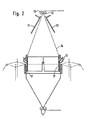
- Fig. 2 die Vorrichtung nach Fig. 1 mit in den Webring eingefahrenem Faltring nach Entspannung der Schlauchblase.
- 1 shows a longitudinal section through the device for forming Z-folds and inserting the Z-fold-provided tube sheet with the folding ring located in its upper position with the tube bladder under tension in a schematic representation, and
- Fig. 2 shows the device of Fig. 1 with the folding ring retracted into the weaving ring after relaxation of the hose bladder.
Von einem üblichen und daher nicht dargestellten Rundwebstuhl sind in der Zeichnung lediglich der Webring 1 und die Fachbildung 2 angedeutet, wobei der aus den Folienbändchen 3 gewebte Rundschlauch 4 nach unten von dem Abzugswalzenpaar 5 abgezogen und gleichzeitig flachgelegt wird. Oberhalb des Webrings 1 ist ein Faltzylinder 6 angeordnet, der aus einer Ringkonsole 7 und einem daran befestigten Zylinder 8 aus relativ dünnem Material besteht. Dieser Zylinder 8 weist vier Einschnitte 9 auf. Sein äussere Durchmesser ist geringer als der innere Durchmesser des Webrings 1, so dass der Zylinder 8 durch Absenken des gesamten Faltzylinders 6 je nach Bedarf mehr oder weniger tief in den Webring 1 eintauchen kann. An der dem Zylinder 8 entgegengesetzten Seite der Ringkonsole 7 ist mit dieser ein Einlaufring 10 fest verbunden, der aus einer Vielzahl von auf eine Achse aufgereihten Teflonröllchen besteht. Über diesem Einlaufring 10 sind zwei Platten 11 und 12 aufeinander zu- und voneinander wegschwenkbar gelagert, zwischen denen die von den Vorzugsrollen 13 transportierte Schlauchfolie 14 hindurchläuft. Wie die Figuren erkennen lassen, sind im Bereich der Einschnitte 9 Klebstoffauftragsdüsen 16 vorgesehen, die gemeinsam mit dem Faltzylinder auf- und ab- und zusätzlich noch relativ zum Faltzylinder bewegbar sind.From a conventional and therefore not shown circular loom, only the weaving ring 1 and shed formation 2 are indicated in the drawing, the circular tube 4 woven from the foil strips 3 being pulled downwards from the pair of draw-off rollers 5 and laid flat at the same time. A folding
Nachstehend wird die Funktion der Vorrichtung beschrieben.The function of the device is described below.
Zunächst einmal wird die Schlauchfolie 14 bei abgeschwenkten Platten 11 und 12 zwischen den Vorzugsrollen 13 und dem Abzugswalzenpaar 5 mit nur geringem Druck durch Injektion mit einer Nadel od. dgl. zu einer Blase aufgeblasen. Während nun der Rundschlauch 4 gewebt wird, wird gleichzeitig die Schlauchfolie 14 als Innenschlauch mit eingezogen. Die Vorzugsrollen 13 und das Walzenpaar 5 sind dabei mit gleicher Umfangsgeschwindigkeit angetrieben. Werden jetzt die Schwenkplatten 11 und 12 aufeinander zu bewegt, wird die Schlauchblase an dieser Stelle zusammengedrückt. Die verdrängte Luft bewirkt, dass sich die Folie 14 zwischen dem Faltzylinder 6 und dem Webring 1 nach aussen drückt und eine Wulst 15 bildet. Je nach Breite der Einschnitte 9 kann sich auch hier die Folie 14 herausdrücken. Ist die Wulst 15 gebildet, so fährt der Faltzylinder mit gegenüber der durch Abzugswalzen 5 bestimmten Abzugsgeschwindigkeit erhöhter Geschwindigkeit nach unten und taucht so weit in den Webring 1 ein, bis sich eine Z-Falte 17 gewünschter Tiefe gebildet hat.First of all, when the
Die Vorzugsrollen 13 werden während dieser Phase mit erhöhter, der Geschwindigkeit des Faltzylinders 6 angepasster Geschwindigkeit angetrieben. In diesem Augenblick wird sowohl die Absenkgeschwindigkeit des Faltzylinders 6 als auch die Geschwindigkeit der Vorzugsrollen 13 der Geschwindigkeit des Walzenpaares 5 angepasst, welches stets mit gleichbleibender Umfangsgeschwindigkeit angetrieben wird. Nachdem dies geschehen ist, tritt Klebstoff aus den Düsen 16 aus, die beispielsweise über nicht dargestellte hydraulische Kolben-Zylinder-Einheiten mit der Ringkonsole 7 verbunden sind. Durch Beaufschlagung dieser Kolben-Zylinder-Einheiten werden die Düsen 16 nach oben, also in Richtung auf die Konsole 7 hin bewegt, wodurch vier Klebstoffstreifen auf die Schlauchfolie 14 gleichmässig am Umfang verteilt aufgebracht werden. Die Düsen werden ausgeschaltet und der Faltzylinder 6 fährt noch so weit in den Webring hinein, bis die Schlauchfolie 14 durch die Klebstoffstreifen mit dem Rundgewebeschlauch 4 verbunden ist. Danach fahren sowohl der Faltzylinder 6 wie auch die an der Konsole 7 befestigten Düsen 16 wieder in ihre in Fig. 1 dargestellte Ausgangslage zurück. Vorher sind allerdings schon die Platten 11 und 12 auseinandergefahren worden, um zu verhindern, dass die Z- Falte während der Aufwärtsbewegung des Faltzylinders 6 wieder auseinandergezogen wird.During this phase, the
Von der nach diesem Verfahren gebildeten Rundgewebebahn mit eingelegtem Innenschlauch werden dann Säcke gebildet, beispielsweise 50-kg-Säcke, bei denen im Bereich des oberen Öffnungsrandes der Innen- mit dem Aussensack durch vier Klebstoffstreifen verbunden ist, so dass beim Öffnen zwecks Befüllen der Innensack auf jeden Fall mit aufgezogen wird. Während des Befüllvorgangs wird die unmittelbar unterhalb der Klebstoffstreifen eingelegte Z-Falte von dem einfliessenden Gut nach und nach aufgezogen, so dass sich der Innensack spannungsfrei an den Aussensack anlegen kann und somit keinerlei tragende Funktion auszuüben hat.Sacks are then formed from the round fabric web with the inner tube inserted, for example 50 kg sacks, in which the inner sack is connected to the outer sack by four adhesive strips in the area of the upper opening edge, so that the inner sack opens when it is opened for filling is brought up in any case. During the filling process, the Z-fold inserted immediately below the adhesive strips is gradually pulled open by the inflowing material, so that the inner sack can lie on the outer sack without tension and thus has no supporting function.
Claims (7)
Priority Applications (1)
| Application Number | Priority Date | Filing Date | Title |
|---|---|---|---|
| AT82102283T ATE11308T1 (en) | 1981-03-25 | 1982-03-19 | METHOD AND DEVICE FOR INSERTING A HOSE WAY WITH THE FORMATION OF Z-FOLDS IN A ROUND FABRIC HOSE. |
Applications Claiming Priority (2)
| Application Number | Priority Date | Filing Date | Title |
|---|---|---|---|
| DE3111829 | 1981-03-25 | ||
| DE3111829 | 1981-03-25 |
Publications (2)
| Publication Number | Publication Date |
|---|---|
| EP0061174A1 EP0061174A1 (en) | 1982-09-29 |
| EP0061174B1 true EP0061174B1 (en) | 1985-01-16 |
Family
ID=6128286
Family Applications (1)
| Application Number | Title | Priority Date | Filing Date |
|---|---|---|---|
| EP82102283A Expired EP0061174B1 (en) | 1981-03-25 | 1982-03-19 | Process and apparatus for the insertion of a tube in a tubular fabric with formation of z folds |
Country Status (7)
| Country | Link |
|---|---|
| US (1) | US4462431A (en) |
| EP (1) | EP0061174B1 (en) |
| JP (1) | JPS57171740A (en) |
| AT (1) | ATE11308T1 (en) |
| BR (1) | BR8201666A (en) |
| DE (1) | DE3261897D1 (en) |
| SU (1) | SU1077576A3 (en) |
Families Citing this family (6)
| Publication number | Priority date | Publication date | Assignee | Title |
|---|---|---|---|---|
| EP0375779A4 (en) * | 1988-06-17 | 1991-06-19 | Ashimori Kogyo Kabushiki Kaisha | Method and apparatus for continuously producing long bias fabric |
| FR2740146B1 (en) * | 1995-10-18 | 1998-01-16 | Caer Yves | CONTINUOUS MANUFACTURING MACHINE FOR DOUBLE TEXTILE TUBES |
| US7094936B1 (en) | 2001-07-20 | 2006-08-22 | Great Lakes Chemical Corporation | Process for preparing halogenated alkanes |
| CN104528449A (en) * | 2014-12-30 | 2015-04-22 | 南京市高举高投资有限公司 | Automatic packaging bag folding machine and folding packaging bag |
| CN113291916B (en) * | 2021-06-04 | 2023-04-07 | 东莞市德合智能设备有限公司 | Efficient and rapid plastic bag folding and rolling equipment |
| CN113428721B (en) * | 2021-06-18 | 2024-04-12 | 杭州欣浩医疗科技有限公司 | Inner sleeve folding device |
Family Cites Families (8)
| Publication number | Priority date | Publication date | Assignee | Title |
|---|---|---|---|---|
| DE632547C (en) * | 1934-11-07 | 1936-07-09 | Guido Horn Maschinenfabrik | Woven ring and method and apparatus for its manufacture |
| DE869627C (en) * | 1951-08-18 | 1953-03-05 | Ver Seidenwebereien A G | Device for the distortion-free pulling off of a continuously accumulating woven fabric tube pulled over a cylinder onto a winding beam lying perpendicular to the cylinder axis |
| US2913799A (en) * | 1953-12-30 | 1959-11-24 | Sagem | Woven, lined tubular fabric and method and means for manufacturing same |
| GB1281234A (en) * | 1969-07-23 | 1972-07-12 | Reinhard Schulte G M B H | Improvements in or relating to the treatment of textile webs |
| US4065339A (en) * | 1972-01-18 | 1977-12-27 | Bayer Aktiengesellschaft | Process for producing fibre reinforced plastic tubes with flanges |
| IT1101349B (en) * | 1978-12-22 | 1985-09-28 | Mcplefan Spa | CIRCULAR FRAME WITH FLOATING DILATOR FOR TUBULAR ARTICLES |
| DE2939970C2 (en) * | 1979-10-02 | 1982-07-01 | Windmöller & Hölscher, 4540 Lengerich | Device for laying a sheet of film in Z-folds |
| US4373979A (en) * | 1980-09-26 | 1983-02-15 | Workman Bag Company Ltd. | Sealed bags of plastic materials |
-
1982
- 1982-03-19 EP EP82102283A patent/EP0061174B1/en not_active Expired
- 1982-03-19 DE DE8282102283T patent/DE3261897D1/en not_active Expired
- 1982-03-19 AT AT82102283T patent/ATE11308T1/en not_active IP Right Cessation
- 1982-03-24 JP JP57048070A patent/JPS57171740A/en active Pending
- 1982-03-24 US US06/361,339 patent/US4462431A/en not_active Expired - Fee Related
- 1982-03-24 BR BR8201666A patent/BR8201666A/en unknown
- 1982-03-24 SU SU823410779A patent/SU1077576A3/en active
Also Published As
| Publication number | Publication date |
|---|---|
| EP0061174A1 (en) | 1982-09-29 |
| DE3261897D1 (en) | 1985-02-28 |
| BR8201666A (en) | 1983-02-16 |
| JPS57171740A (en) | 1982-10-22 |
| ATE11308T1 (en) | 1985-02-15 |
| SU1077576A3 (en) | 1984-02-29 |
| US4462431A (en) | 1984-07-31 |
Similar Documents
| Publication | Publication Date | Title |
|---|---|---|
| DE2357424A1 (en) | METHOD AND EQUIPMENT FOR MANUFACTURING AND FILLING PACKAGES | |
| DE2854586A1 (en) | METHOD AND DEVICE FOR THE PRODUCTION OF PLASTIC SLEEVES | |
| DE2632853C2 (en) | Apparatus for making bags from a two-ply sheet of thermoplastic material | |
| DE1296790B (en) | Device for the production of rigid pipes | |
| EP0061174B1 (en) | Process and apparatus for the insertion of a tube in a tubular fabric with formation of z folds | |
| DE6916834U (en) | DEVICE FOR THE PRODUCTION OF PACKAGING, PREFERABLY FLAT-BOTTOM PACKAGING, FROM A CONTINUOUS STRIP OF FILM. | |
| DE2504295A1 (en) | DEVICE FOR THE MANUFACTURING OF DISPOSABLE DIAPERS | |
| DE2529024A1 (en) | DEVICE AND PROCESS FOR THE CONTINUOUS MANUFACTURING AND FILLING OF TAMPON SACKS | |
| EP0673750B1 (en) | Device for flattening a blown tubular thermoplastic film | |
| DE2508862A1 (en) | MULTI-LAYER FILM AND METHOD OF MANUFACTURING IT | |
| DE1179089B (en) | Machine for the production of tube sections with side gussets for folding bags | |
| DE3926963C1 (en) | ||
| DE2648235C2 (en) | Device for the automatic production of multiple folded, sewn bag bottoms | |
| DE2925553C2 (en) | Device for inserting a hose in a tubular fabric | |
| DE2165191A1 (en) | Sausage skin ravelling machine - with automatic end sealing assembly | |
| DE1486975C (en) | Method and device for the manufacture of multi-layer bags or sacks | |
| DE2510515A1 (en) | Forming deep folds in blown tubular films - by pressing- in one film side-simultaneously raising film in straight path | |
| DE2752672B2 (en) | Device for forming a connecting sleeve with an annular groove | |
| DE2437840C2 (en) | Method and device for forming a tube | |
| DE2028787B2 (en) | Device for aligning and supporting the turns of a prefabricated reinforcement helix | |
| DE1604609B2 (en) | DEVICE FOR MANUFACTURING BAGS OR SACKS FROM THERMOPLASTIC PLASTIC FILMS | |
| DE2231144C3 (en) | Method and device for shirring casings | |
| DE1511014B2 (en) | Device for producing a closed tube from rigid strip material for producing filled packs, preferably tetrahedral packs | |
| DE2329806C3 (en) | Method and device for turning a flexible hose inside out | |
| DE1504404C (en) | Device for squeezing a tube made of thermoplastic material with a pair of squeezing rollers |
Legal Events
| Date | Code | Title | Description |
|---|---|---|---|
| PUAI | Public reference made under article 153(3) epc to a published international application that has entered the european phase |
Free format text: ORIGINAL CODE: 0009012 |
|
| AK | Designated contracting states |
Designated state(s): AT CH DE FR GB IT |
|
| 17P | Request for examination filed |
Effective date: 19830128 |
|
| ITF | It: translation for a ep patent filed |
Owner name: BUGNION S.P.A. |
|
| GRAA | (expected) grant |
Free format text: ORIGINAL CODE: 0009210 |
|
| AK | Designated contracting states |
Designated state(s): AT CH DE FR GB IT LI |
|
| REF | Corresponds to: |
Ref document number: 11308 Country of ref document: AT Date of ref document: 19850215 Kind code of ref document: T |
|
| REF | Corresponds to: |
Ref document number: 3261897 Country of ref document: DE Date of ref document: 19850228 |
|
| ET | Fr: translation filed | ||
| PLBE | No opposition filed within time limit |
Free format text: ORIGINAL CODE: 0009261 |
|
| STAA | Information on the status of an ep patent application or granted ep patent |
Free format text: STATUS: NO OPPOSITION FILED WITHIN TIME LIMIT |
|
| 26N | No opposition filed | ||
| PG25 | Lapsed in a contracting state [announced via postgrant information from national office to epo] |
Ref country code: GB Effective date: 19890319 |
|
| PG25 | Lapsed in a contracting state [announced via postgrant information from national office to epo] |
Ref country code: LI Effective date: 19890331 Ref country code: CH Effective date: 19890331 |
|
| GBPC | Gb: european patent ceased through non-payment of renewal fee | ||
| REG | Reference to a national code |
Ref country code: CH Ref legal event code: PL |
|
| PGFP | Annual fee paid to national office [announced via postgrant information from national office to epo] |
Ref country code: FR Payment date: 19900228 Year of fee payment: 9 |
|
| PGFP | Annual fee paid to national office [announced via postgrant information from national office to epo] |
Ref country code: AT Payment date: 19900306 Year of fee payment: 9 |
|
| PG25 | Lapsed in a contracting state [announced via postgrant information from national office to epo] |
Ref country code: AT Effective date: 19910319 |
|
| PG25 | Lapsed in a contracting state [announced via postgrant information from national office to epo] |
Ref country code: FR Effective date: 19911129 |
|
| REG | Reference to a national code |
Ref country code: FR Ref legal event code: ST |
|
| PGFP | Annual fee paid to national office [announced via postgrant information from national office to epo] |
Ref country code: DE Payment date: 19920407 Year of fee payment: 11 |
|
| PG25 | Lapsed in a contracting state [announced via postgrant information from national office to epo] |
Ref country code: DE Effective date: 19931201 |