EP0059706B1 - Dispersive optical device - Google Patents
Dispersive optical device Download PDFInfo
- Publication number
- EP0059706B1 EP0059706B1 EP81900924A EP81900924A EP0059706B1 EP 0059706 B1 EP0059706 B1 EP 0059706B1 EP 81900924 A EP81900924 A EP 81900924A EP 81900924 A EP81900924 A EP 81900924A EP 0059706 B1 EP0059706 B1 EP 0059706B1
- Authority
- EP
- European Patent Office
- Prior art keywords
- grating
- light
- gratings
- substrate
- angle
- Prior art date
- Legal status (The legal status is an assumption and is not a legal conclusion. Google has not performed a legal analysis and makes no representation as to the accuracy of the status listed.)
- Expired
Links
- 230000003287 optical effect Effects 0.000 title claims description 5
- 230000005540 biological transmission Effects 0.000 claims abstract description 5
- 239000000758 substrate Substances 0.000 claims description 39
- 239000011248 coating agent Substances 0.000 claims description 6
- 238000000576 coating method Methods 0.000 claims description 6
- 239000002250 absorbent Substances 0.000 claims description 3
- 239000011521 glass Substances 0.000 abstract 3
- 238000001228 spectrum Methods 0.000 description 3
- 239000005329 float glass Substances 0.000 description 2
- 239000003973 paint Substances 0.000 description 2
- 239000006185 dispersion Substances 0.000 description 1
- 238000006073 displacement reaction Methods 0.000 description 1
- 230000000694 effects Effects 0.000 description 1
- 230000037431 insertion Effects 0.000 description 1
- 238000003780 insertion Methods 0.000 description 1
- 238000004519 manufacturing process Methods 0.000 description 1
- 230000000007 visual effect Effects 0.000 description 1
Images
Classifications
-
- G—PHYSICS
- G01—MEASURING; TESTING
- G01J—MEASUREMENT OF INTENSITY, VELOCITY, SPECTRAL CONTENT, POLARISATION, PHASE OR PULSE CHARACTERISTICS OF INFRARED, VISIBLE OR ULTRAVIOLET LIGHT; COLORIMETRY; RADIATION PYROMETRY
- G01J3/00—Spectrometry; Spectrophotometry; Monochromators; Measuring colours
- G01J3/12—Generating the spectrum; Monochromators
- G01J3/18—Generating the spectrum; Monochromators using diffraction elements, e.g. grating
- G01J3/1804—Plane gratings
-
- G—PHYSICS
- G02—OPTICS
- G02B—OPTICAL ELEMENTS, SYSTEMS OR APPARATUS
- G02B27/00—Optical systems or apparatus not provided for by any of the groups G02B1/00 - G02B26/00, G02B30/00
- G02B27/10—Beam splitting or combining systems
- G02B27/1006—Beam splitting or combining systems for splitting or combining different wavelengths
-
- G—PHYSICS
- G02—OPTICS
- G02B—OPTICAL ELEMENTS, SYSTEMS OR APPARATUS
- G02B27/00—Optical systems or apparatus not provided for by any of the groups G02B1/00 - G02B26/00, G02B30/00
- G02B27/10—Beam splitting or combining systems
- G02B27/106—Beam splitting or combining systems for splitting or combining a plurality of identical beams or images, e.g. image replication
-
- G—PHYSICS
- G02—OPTICS
- G02B—OPTICAL ELEMENTS, SYSTEMS OR APPARATUS
- G02B27/00—Optical systems or apparatus not provided for by any of the groups G02B1/00 - G02B26/00, G02B30/00
- G02B27/10—Beam splitting or combining systems
- G02B27/1086—Beam splitting or combining systems operating by diffraction only
- G02B27/1093—Beam splitting or combining systems operating by diffraction only for use with monochromatic radiation only, e.g. devices for splitting a single laser source
-
- G—PHYSICS
- G02—OPTICS
- G02B—OPTICAL ELEMENTS, SYSTEMS OR APPARATUS
- G02B27/00—Optical systems or apparatus not provided for by any of the groups G02B1/00 - G02B26/00, G02B30/00
- G02B27/10—Beam splitting or combining systems
- G02B27/12—Beam splitting or combining systems operating by refraction only
- G02B27/126—The splitting element being a prism or prismatic array, including systems based on total internal reflection
-
- G—PHYSICS
- G02—OPTICS
- G02B—OPTICAL ELEMENTS, SYSTEMS OR APPARATUS
- G02B27/00—Optical systems or apparatus not provided for by any of the groups G02B1/00 - G02B26/00, G02B30/00
- G02B27/42—Diffraction optics, i.e. systems including a diffractive element being designed for providing a diffractive effect
- G02B27/4233—Diffraction optics, i.e. systems including a diffractive element being designed for providing a diffractive effect having a diffractive element [DOE] contributing to a non-imaging application
- G02B27/4244—Diffraction optics, i.e. systems including a diffractive element being designed for providing a diffractive effect having a diffractive element [DOE] contributing to a non-imaging application in wavelength selecting devices
-
- G—PHYSICS
- G02—OPTICS
- G02B—OPTICAL ELEMENTS, SYSTEMS OR APPARATUS
- G02B27/00—Optical systems or apparatus not provided for by any of the groups G02B1/00 - G02B26/00, G02B30/00
- G02B27/42—Diffraction optics, i.e. systems including a diffractive element being designed for providing a diffractive effect
- G02B27/4272—Diffraction optics, i.e. systems including a diffractive element being designed for providing a diffractive effect having plural diffractive elements positioned sequentially along the optical path
-
- G—PHYSICS
- G02—OPTICS
- G02F—OPTICAL DEVICES OR ARRANGEMENTS FOR THE CONTROL OF LIGHT BY MODIFICATION OF THE OPTICAL PROPERTIES OF THE MEDIA OF THE ELEMENTS INVOLVED THEREIN; NON-LINEAR OPTICS; FREQUENCY-CHANGING OF LIGHT; OPTICAL LOGIC ELEMENTS; OPTICAL ANALOGUE/DIGITAL CONVERTERS
- G02F1/00—Devices or arrangements for the control of the intensity, colour, phase, polarisation or direction of light arriving from an independent light source, e.g. switching, gating or modulating; Non-linear optics
- G02F1/29—Devices or arrangements for the control of the intensity, colour, phase, polarisation or direction of light arriving from an independent light source, e.g. switching, gating or modulating; Non-linear optics for the control of the position or the direction of light beams, i.e. deflection
-
- H—ELECTRICITY
- H01—ELECTRIC ELEMENTS
- H01S—DEVICES USING THE PROCESS OF LIGHT AMPLIFICATION BY STIMULATED EMISSION OF RADIATION [LASER] TO AMPLIFY OR GENERATE LIGHT; DEVICES USING STIMULATED EMISSION OF ELECTROMAGNETIC RADIATION IN WAVE RANGES OTHER THAN OPTICAL
- H01S3/00—Lasers, i.e. devices using stimulated emission of electromagnetic radiation in the infrared, visible or ultraviolet wave range
- H01S3/005—Optical devices external to the laser cavity, specially adapted for lasers, e.g. for homogenisation of the beam or for manipulating laser pulses, e.g. pulse shaping
Definitions
- the invention relates to a dispersive optical device for use such as a spectroscope, polarizer, monochromator or the like, or for use as a basic component for a monochromator, spectrograph, spectophotometer, polarizer or the like.
- the inventive dispersive optical device is in the form of a diffraction grating for use as a basic element for a monochromator, a spectroscope or the like, and is characterised by a first and a second reflection or transmission grating so arranged on a common substrate that their planes and their grating rules are parallel to each other, the mutual arrangement of the two gratings being such that the light diffracted by the first grating passes through said substrate before striking the second grating.
- the angle between a normal to a grating and a line between the gratings should attain at least 60° and preferably at least 70°.
- the upper limit of the angle is 90°, for natural reasons, but attains in practice to about 88°.
- the angle is selected to advantage within the interval 80-85°.
- the angular variation will be small for rays between the gratings. This signifies that only a correspondingly small spectrum portion of parallel light incident on the first grating will strike the second grating. Since the gratings are mutually the same, light diffracted by the second grating will be parallel to the light incident on the first grating.
- the angle of the member i.e. the grating
- the member when the member is utilized as a monochromator, for example, it can be arranged for light of a predetermined wavelength range to leave the output of the member by setting a given angle between incident light and the member.
- a focussing lens can be arranged behind the member output with a slit after the lens, suitably at its focal point, so that aligning errors are eliminated, as well as extraneous light wavelengths, only the whole of the pertinent pencil of rays being looked after.
- the dispersive member can be provided with a wavelength scale which is readable at the output from the second grating, so that the wavelength of the light observed at the output of the second grating can be read off by eye directly.
- the member is built up on a transparent substrate with planar parallel surfaces, e.g. a plate of so-called float glass, a grating being arranged on each chief surface of the substrate at opposed ends thereof.
- the gratings are preferably protected by some kind of covering on their surfaces facing away from the substrate.
- a light-absorbing coating e.g. a black paint, the refractive index of which is close to that of the substrate, except at the surfaces of the substrate used as input, output and total reflection surfaces.
- the gratings can be arranged opposite, and adjacent each other between a first and a second planar parallel substrate, the substrates being arranged mutually parallel and adjacent.
- a third planar parallel substrate is preferably arranged perpendicular to said first and second substrate at one end thereof.
- a mirror means can hereby be arranged at the free surface of the third substrate.
- Light which is diffracted by the first grating can thus be arranged for total reflection at the free surface of the first substrate, for subsequently striking the first mirror means, whereat it is directed towards the free surface of the second substrate for being totally reflected there.
- the light can subsequently be arranged for directing towards the second grating, where it is diffracted and departs from the member.
- the departing light will, however, be mirror-inverted in relation to the light incident on the first grating, although the member can be made such that light which is totally reflected at the free surface of the second substrate strikes a second mirror means at the free end of the second substrate, for direction towards the second grating with an angle of incidence corresponding to the diffraction angle at the first grating.
- both gratings of the member are adapted mutually adjacent and opposite, the source of the light incident on the first grating can be observed with full sharpness and substantially without parallax.
- Said first and second gratings can possibly constitute opposing sides of a single grating element.
- a light-absorbent coating should be arranged to surround the member excepting the substrate surfaces which form the input and output of the member and the substrate surfaces at which said total reflections are arranged to occur.
- grating line density, width of grating and distance between the gratings in the ray path it can be ensured that only light wavelengths within an interval determined by said factors strike the second grating. Due to the second grating having the same grating frequency as the first grating, light which is defracted in the second grating will have the same direction as light incident on the first grating. Said light wavelength range can be varied by varying the angle between the first grating and incident light.
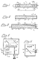
- a dispersive member 1 is illustrated in Figure 1, and includes a transparent substrate 2, e.g. of float glass, with planar parallel chief surfaces 21, 22. At one end zone of the member 1 there is a first reflection grating 3 arranged on the surface 22. At the other end zone of said member 1 there is a second reflection grating 4 arranged on the surface 21.
- the substrate 2 and gratings 3, 4 are outwardly covered by a light-absorbent medium 5, e.g. a black paint, with a reflective index as near to that of the substrate as possible, except at the substrate surfaces 6, 7 opposite the respective grating 3, 4.
- the surface 6 can be the input of the member, in which case the surface 7 constitutes its output.
- the gratings 3, 4 have the same grating frequency and mutually parallel scores or rulings, extending normal to the plan of the Figure 1.
- the grating 4 will only be struck by light with a wavelength between ⁇ max and ⁇ min , ⁇ max and ⁇ min are obtained by insertion of ⁇ max and ⁇ min in the grating formula above).
- grating 4 A portion of the light incident on the grating 4 will be diffracted. If grating 4 has the same frequency as grating 3, the diffraction angle will be equal to the angle of incidence on the grating 3. i.e. ⁇ 2 . The light leaving the grating 4 will thus be parallel to the light incident on the grating 3.
- dispersive member according to Figure 1 is utilizable as a spectroscope and is directly readable by the human eye.
- Figure 4 illustrates a member 1 according to Figure 1, which is pivotably mounted about a shaft substantially in the plane of the grating parallel to the grating lines, and at half the width of the grating 3.
- the member 1 is enclosed in a housing 30 having an opening 31 opposite the grating 3.
- Figure 3 illustrates a modified embodiment of a dispersive member in accordance with the invention.
- the function of the member according to Figure 3 is the same as for the element according to Figure 1,
- the gratings are, however, arranged mutually opposite and adjacent, so that a direct through-sighting is enabled from the output 7 through the gratings and through the input 6, or in the opposite direction.
- transmission gratings 3', 4' are utilized, which are applied to the substrate 2. Otherwise, the same conditions apply as for Figure 1.
- the member according to Figure 3 includes two planar parallel substrates 102, 103, on which the gratings 3, 4 are applied directly opposite each other.
- the substrates 102, 103 are placed on against the other.
- a third substrate 104 is abutted tightly against the ends of the substrates 102, 103.
- Both ends of the substrate 104 are provided with a reflecting coating 107, 108 to form mirrors at right angles to the plane of the gratings 3, 4.
- a light-absorbing coating 5 is applied to the member, excepting at its input 6 and output 7, and possibly the positions 105 and 106.
- the free surfaces of the substrates 102, 103 may be coated to allow total reflection of light diffracted by grating 3, as is illustrated by the dashed ray path.
- a medium with a lower refractive index than that of the substrate can be applied at the positions 105, 106, whereat the coating 5 can be applied to the medium in the positions 105, 106.
- Incident light is defracted at the grating 3, mirrored at the position 105 at the mirror 107, and at the position 106 at the mirror 108 to strike the grating 4 at an angle of incidence corresponding to the diffraction angle at the grating 3.
- Figures 4 and 5 illustrate a device in accordance with the invention, which includes a member according to Figure 1 and is adapted for utilization as a monochromator and/or spectrograph or the like.
- the monochromator according to Figure 4 comprises a housing 30 with an opening 31 for incidence light. At the opening 31 a wide slit can be arranged to afford a relatively large wavelength resolution. Furthermore, a focussing element can be arranged in connection with the opening to provide focussing towards the measuring point.
- a mirror 3Z is arranged to deflect incident light by 90°.
- a mirror 33 parallel to the mirror 32, deflects the light to the incident direction.
- the mirror 33 is arranged parallel displaceable at right-angles to the incident light.
- the mirror 33 is arranged to direct incident light to the input 6 of the element 1.
- the member 1 is pivotably mounted on a shaft 34, which is mounted in the plane of the grating 4 at half the width thereof.
- the shaft 34 extends in the normal plane to Figure 4.
- the focussing lens 35 is arranged opposite the output 7 of the member 1 to focus departing light towards a slit 36 in the housing 30.
- the slit 36 is in a position defined by a line through the shaft 34 parallel to the incident light.
- a screw 37 is connected to the member 1 in a position at a distance from the shaft 34.
- the screw 37 is adapted to provide pivoting of the member 1 about the shaft 34 when the screw is turned. Furthermore, the screw 37 or the member 1 is connected to the mirror 33 to provide parallel displacement of the mirror 33, so that light deflected by the mirror 33 strikes the input 6 of the member 1 irrespective of the pivotal position of the member.
- the screw 37 has a wheel 39 and is connected to a revolution counter incidating the angle of the member 1, and thus the light wavelength passing through the slit 36.
- Figure 5 illustrates a mirror 41, pivotably mounted on a shaft 40 with an operating wheel 43.
- An eyepiece 42 is mounted in the upper part of the housing 30.
- the lens 35 focusses in front of the eyepiece 42, and a graduation scale 49 is arranged at the focus of the lens 35.
- the scale 49 extends normal to the plane of the Figure 5.
- the mirror 40 and eyepiece 42 thus allow visual scanning of the light, and the scale provides an indication of the wavelength in question.
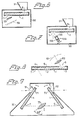
- Figure 6 illustrates an apparatus housing 50 with an opening 51, in the housing 50 there is a member 1 according to Figure 1, mounted with the input 6 opposite the opening 51, so that light coming through the opening strikes the input 6 substantially normal to the grating 3.
- a focussing lens 55 is arranged at the output 7 of the member 1, and a diode array 59 is arranged after the lens 55. This diode array can then sense the focussing position, and thereby register the detected wavelength.
- the apparatus according to Figure 6 thus constitutes a spectograph.
- Figure 7 illustrates a spectrophotometer in accordance with the invention, the rigidly mounted lens 55 and diode array 59 in Figure 5 being replaced by a detector means 156, which is pivotable about a shaft through the centre of the grating 4.
- the means 156 contains a focussing lens 155 and a detector 159. For the determination of the wavelength of the light on the detector 159, the angle of the means 156 to the grating 4 is read so that a purposeful registration of the scanned spectrum can be obtained.
- Figures 6, 7 illustrate only two examples of a plurality of possible applications, wherein the member in accordance with the invention can be utilized.
- Figure 8 schematically illustrates a member according to Figure 1 with an angle scale 81 and a focussing member 82 depicting the scale at infinity in front of the input 6.
- the scale 81 is suitably arranged to be visible in a marginal area of the image field.
- the angle scale 81 and member 82 can of course be arranged in the apparatuses according to Figures 2 and 3 also.
- the monochromator according to Figure 9 can be said to contain two series-connected members according to Figure 1.
- the departing light is caused to be coaxial with the incident light, and the wavelength of departing light can easily be adjusted by the angular setting of both members 1, whereby the member on the input side is pivotable about a shaft 71 at the centre of the grating 3 and the other member 1 is pivotable about a shaft 72 at the centre of the other grating 4.
- Pivoting both members is arranged to be done simultaneously and to the same extent, so that the angle to incident light of the first member is always the same as the angle of the second member to departing light. No focussing member is required in the apparatus according to Figure 9.
- a focussing lens 75 with large focal length which is arranged between the output of the first member and the input of the second member, has been found to almost double the light intensity of the monochromator, simultaneously the resolution is more or less doubled.
- the lens 75 is arranged at an angle of about 55° to the array path.
Landscapes
- Physics & Mathematics (AREA)
- General Physics & Mathematics (AREA)
- Optics & Photonics (AREA)
- Spectroscopy & Molecular Physics (AREA)
- Electromagnetism (AREA)
- Nonlinear Science (AREA)
- Plasma & Fusion (AREA)
- Engineering & Computer Science (AREA)
- Diffracting Gratings Or Hologram Optical Elements (AREA)
- Spectrometry And Color Measurement (AREA)
- Lasers (AREA)
- Analysing Materials By The Use Of Radiation (AREA)
- Laser Surgery Devices (AREA)
Applications Claiming Priority (1)
| Application Number | Priority Date | Filing Date | Title |
|---|---|---|---|
| SE8003968A SE421568B (sv) | 1980-05-28 | 1980-05-28 | Anordning for uppdelning av en ljusstrale i ett flertal stralar eller omvent |
Publications (2)
| Publication Number | Publication Date |
|---|---|
| EP0059706A1 EP0059706A1 (en) | 1982-09-15 |
| EP0059706B1 true EP0059706B1 (en) | 1984-08-15 |
Family
ID=20341057
Family Applications (2)
| Application Number | Title | Priority Date | Filing Date |
|---|---|---|---|
| EP81900924A Expired EP0059706B1 (en) | 1980-05-28 | 1981-03-30 | Dispersive optical device |
| EP81901289A Expired EP0058667B1 (en) | 1980-05-28 | 1981-05-26 | Device for dividing a laser beam |
Family Applications After (1)
| Application Number | Title | Priority Date | Filing Date |
|---|---|---|---|
| EP81901289A Expired EP0058667B1 (en) | 1980-05-28 | 1981-05-26 | Device for dividing a laser beam |
Country Status (8)
| Country | Link |
|---|---|
| US (2) | US4591270A (OSRAM) |
| EP (2) | EP0059706B1 (OSRAM) |
| JP (2) | JPS57500998A (OSRAM) |
| AT (2) | ATE9041T1 (OSRAM) |
| AU (1) | AU7036181A (OSRAM) |
| DE (2) | DE3165503D1 (OSRAM) |
| SE (1) | SE421568B (OSRAM) |
| WO (2) | WO1981003552A1 (OSRAM) |
Families Citing this family (22)
| Publication number | Priority date | Publication date | Assignee | Title |
|---|---|---|---|---|
| JPS6156331A (ja) * | 1984-07-06 | 1986-03-22 | Harue Sugimoto | 撮影デ−タのフィルム面への写し込み方法 |
| FR2590995B1 (fr) * | 1985-02-26 | 1988-08-19 | Thomson Csf | Dispositif d'interconnexion optique de cartes de composants electroniques dans un coffret et procede de fabrication |
| US4856869A (en) * | 1986-04-08 | 1989-08-15 | Canon Kabushiki Kaisha | Display element and observation apparatus having the same |
| JPH01287924A (ja) * | 1988-03-30 | 1989-11-20 | Hitachi Ltd | コヒーレント制御露光装置 |
| US5119454A (en) * | 1988-05-23 | 1992-06-02 | Polaroid Corporation | Bulk optic wavelength division multiplexer |
| DE3901985C2 (de) * | 1989-01-24 | 1996-12-05 | Deutsch Franz Forsch Inst | Einrichtung und Verfahren zur Erzeugung bewegter Interferenzmuster |
| JPH0315002A (ja) * | 1989-03-06 | 1991-01-23 | Toshihiro Kubota | 光分割器 |
| US4966447A (en) * | 1989-04-28 | 1990-10-30 | At&T Bell Laboratories | Integration of free-space planar optical components |
| US5081637A (en) * | 1989-11-28 | 1992-01-14 | Massachusetts Institute Of Technology | Multiple-laser pump optical system |
| US5185758A (en) * | 1989-11-28 | 1993-02-09 | Massachusetts Institute Of Technology | Multiple-laser pump optical system |
| WO1992002844A1 (en) * | 1990-08-01 | 1992-02-20 | Diomed Limited | High power light source |
| DE19525520C2 (de) * | 1995-07-13 | 1998-03-19 | Zeiss Carl Jena Gmbh | Optische Anordnung zur Einblendung eines Bildes in den Strahlengang eines Mikroskops |
| US5895775A (en) * | 1996-04-19 | 1999-04-20 | Trw Inc. | Microwave grating for dispersive delay lines having non-resonant stubs spaced along a transmission line |
| US6278534B1 (en) * | 1996-11-27 | 2001-08-21 | Kaiser Optical Systems | Dispersive optical device |
| US5949541A (en) * | 1997-04-11 | 1999-09-07 | Lucid, Inc | Spectrophotometer system |
| EP0930549A1 (en) * | 1998-01-13 | 1999-07-21 | Holtronic Technologies Limited | Optic for a total internal reflection (TIR) holographic system |
| US6191911B1 (en) * | 1998-06-12 | 2001-02-20 | The Hong Kong University Of Science And Technology | Positioning apparatus for hard disk servowriter |
| US6869754B2 (en) * | 2001-10-23 | 2005-03-22 | Digital Optics Corp. | Transfer of optical element patterns on a same side of a substrate already having a feature thereon |
| FR2862768B1 (fr) * | 2003-11-21 | 2006-02-24 | Commissariat Energie Atomique | Separateur de polarisation a reseau polarisant |
| DE10359752B4 (de) * | 2003-12-19 | 2015-04-02 | Carl Zeiss Jena Gmbh | Anordnung zur spektralselektiven Strahlführung in optischen Geräten |
| JP2010261767A (ja) * | 2009-05-01 | 2010-11-18 | Canon Inc | 分光装置及びそれを有する画像形成装置 |
| JP7270219B2 (ja) * | 2019-10-07 | 2023-05-10 | パナソニックIpマネジメント株式会社 | 光合波器及びそれを用いた画像投影装置 |
Family Cites Families (23)
| Publication number | Priority date | Publication date | Assignee | Title |
|---|---|---|---|---|
| US3095475A (en) * | 1960-09-14 | 1963-06-25 | Technicolor Corp Of America | Smoothing spatially discontinuous images |
| USRE26617E (en) * | 1967-03-28 | 1969-06-24 | Optical prism unit and manufacture thereof | |
| US3549239A (en) * | 1968-11-19 | 1970-12-22 | United Aircraft Corp | Optical signal processor |
| FR2068014A5 (OSRAM) * | 1969-11-25 | 1971-08-20 | Thomson Csf | |
| US3603668A (en) * | 1970-01-29 | 1971-09-07 | Philips Corp | Composite diffraction grating formed from superimposed aligned gratings |
| US3698795A (en) * | 1971-01-26 | 1972-10-17 | Acton Research Corp | Diffraction grating with two diffracting surfaces |
| DE2225870A1 (de) * | 1972-05-27 | 1973-12-06 | Konrad Dr Hoffmann | Gittermonochromator, insbesonders fuer die farbmetrik |
| US3861801A (en) * | 1973-06-18 | 1975-01-21 | Perkin Elmer Corp | Device for sampling laser beams |
| US3879109A (en) * | 1973-06-21 | 1975-04-22 | Kms Fusion Inc | Laser waveform generator |
| DE2427236C2 (de) * | 1974-06-06 | 1985-09-05 | Ernst Leitz Wetzlar Gmbh, 6330 Wetzlar | Beugung von interferenzfähigem Licht |
| DE2508366C3 (de) * | 1975-02-26 | 1979-05-17 | Erwin Sick Gmbh Optik-Elektronik, 7808 Waldkirch | Optische Vorrichtung mit einem Lichtvorhang |
| DE2527223C2 (de) * | 1975-06-19 | 1985-06-20 | Ernst Leitz Wetzlar Gmbh, 6330 Wetzlar | Abtastgitter für einen Schärfedetektor |
| DE2555559A1 (de) * | 1975-12-10 | 1977-06-16 | Nils Allan Danielsson | Verfahren zur erzeugung optischer abbildungen |
| GB1575033A (en) * | 1976-02-02 | 1980-09-17 | Massachusetts Inst Technology | Laser |
| GB1522555A (en) * | 1976-03-03 | 1978-08-23 | Crosfield Electronics Ltd | Beam splitter |
| JPS52108145A (en) * | 1976-03-09 | 1977-09-10 | Mitsubishi Electric Corp | Double refraction filter |
| US4060327A (en) * | 1976-09-13 | 1977-11-29 | International Business Machines Corporation | Wide band grating spectrometer |
| FR2394789A1 (fr) * | 1976-10-26 | 1979-01-12 | Anvar | Spectroscope a reseau, a incidence rasante |
| SU612535A1 (ru) * | 1976-12-24 | 1979-02-28 | Ленинградский Электротехнический Институт Связи Им. Профессора М.А.Бонч-Бруевича | Полосовой оптический фильтр |
| FR2398318A1 (fr) * | 1977-07-21 | 1979-02-16 | Quantel Sa | Element de filtrage optique et dispositif d'affinement spectral en comportant application |
| SU672598A2 (ru) * | 1977-12-20 | 1979-07-05 | Предприятие П/Я Р-6681 | Оптическа система двойного изображени |
| DE3000402A1 (de) * | 1979-01-19 | 1980-07-31 | Smiths Industries Ltd | Anzeigevorrichtung |
| JPS6126A (ja) * | 1984-06-08 | 1986-01-06 | Mitsui Petrochem Ind Ltd | イソブチレンの製造方法 |
-
1980
- 1980-05-28 SE SE8003968A patent/SE421568B/sv not_active IP Right Cessation
-
1981
- 1981-03-30 US US06/346,044 patent/US4591270A/en not_active Expired - Fee Related
- 1981-03-30 JP JP56501208A patent/JPS57500998A/ja active Pending
- 1981-03-30 DE DE8181900924T patent/DE3165503D1/de not_active Expired
- 1981-03-30 EP EP81900924A patent/EP0059706B1/en not_active Expired
- 1981-03-30 AT AT81900924T patent/ATE9041T1/de not_active IP Right Cessation
- 1981-03-30 AU AU70361/81A patent/AU7036181A/en not_active Abandoned
- 1981-03-30 WO PCT/SE1981/000101 patent/WO1981003552A1/en not_active Ceased
- 1981-05-26 JP JP56501751A patent/JPS57500951A/ja active Pending
- 1981-05-26 US US06/346,041 patent/US4397525A/en not_active Expired - Fee Related
- 1981-05-26 EP EP81901289A patent/EP0058667B1/en not_active Expired
- 1981-05-26 AT AT81901289T patent/ATE8938T1/de not_active IP Right Cessation
- 1981-05-26 WO PCT/SE1981/000156 patent/WO1981003551A1/en not_active Ceased
- 1981-05-26 DE DE8181901289T patent/DE3165378D1/de not_active Expired
Also Published As
| Publication number | Publication date |
|---|---|
| DE3165503D1 (en) | 1984-09-20 |
| EP0058667A1 (en) | 1982-09-01 |
| JPS57500951A (OSRAM) | 1982-05-27 |
| US4591270A (en) | 1986-05-27 |
| DE3165378D1 (en) | 1984-09-13 |
| SE8003968L (OSRAM) | 1981-11-29 |
| AU7036181A (en) | 1981-12-21 |
| EP0059706A1 (en) | 1982-09-15 |
| WO1981003552A1 (en) | 1981-12-10 |
| ATE9041T1 (de) | 1984-09-15 |
| WO1981003551A1 (en) | 1981-12-10 |
| JPS57500998A (OSRAM) | 1982-06-03 |
| SE421568B (sv) | 1982-01-04 |
| ATE8938T1 (de) | 1984-08-15 |
| US4397525A (en) | 1983-08-09 |
| EP0058667B1 (en) | 1984-08-08 |
Similar Documents
| Publication | Publication Date | Title |
|---|---|---|
| EP0059706B1 (en) | Dispersive optical device | |
| US4129781A (en) | Film thickness measuring apparatus and method | |
| US5106196A (en) | Single adjustment specular reflection accessory for spectroscopy | |
| US4440468A (en) | Planar waveguide bragg lens and its utilization | |
| KR100356108B1 (ko) | 이중 통과 에탈론 분광계 | |
| CA1101239A (en) | Spectrofluorometer having optical scrambler | |
| US4836634A (en) | Wavelength multiplexer/demultiplexer using optical fibers | |
| JPH073344B2 (ja) | エンコ−ダ− | |
| US4838645A (en) | Reflecting diffraction grating | |
| WO1993023784A1 (en) | Area-division beamsplitter with broad spectral bandwidth | |
| DK2929307T3 (en) | SPECTROMETER FOR ANALYZING A SPECTRUM SPECTRUM | |
| CA2025204C (en) | Spectrum measuring equipment | |
| JP2010506154A (ja) | 高感度スペクトル分析ユニット | |
| US6646739B2 (en) | Four-stage type monochromator | |
| US20040021942A1 (en) | Depolarizer and spectroscope and polychromater | |
| US7221454B2 (en) | Photopolarimeters and spectrophotopolarimaters with multiple diffraction gratings | |
| JP6097412B2 (ja) | 光学装置 | |
| JP2995985B2 (ja) | 偏光解消板 | |
| GB2086572A (en) | Differential pressure measuring apparatus | |
| US4932780A (en) | Interferometer | |
| US20030007149A1 (en) | Depolarizer and spectroscope | |
| JP2005127943A (ja) | 光計測装置及び分光装置 | |
| US3285124A (en) | High precision pointing interferometer with modified kosters prism | |
| JPH05281041A (ja) | 分光器 | |
| US5049757A (en) | Method for scanning a plurality of optical measuring reflectors and an apparatus for performing the method |
Legal Events
| Date | Code | Title | Description |
|---|---|---|---|
| PUAI | Public reference made under article 153(3) epc to a published international application that has entered the european phase |
Free format text: ORIGINAL CODE: 0009012 |
|
| 17P | Request for examination filed |
Effective date: 19820621 |
|
| AK | Designated contracting states |
Kind code of ref document: A1 Designated state(s): AT CH DE FR GB NL SE |
|
| R17P | Request for examination filed (corrected) |
Effective date: 19820621 |
|
| GRAA | (expected) grant |
Free format text: ORIGINAL CODE: 0009210 |
|
| AK | Designated contracting states |
Kind code of ref document: B1 Designated state(s): AT CH DE FR GB LI NL SE |
|
| PG25 | Lapsed in a contracting state [announced via postgrant information from national office to epo] |
Ref country code: NL Effective date: 19840815 Ref country code: AT Effective date: 19840815 |
|
| REF | Corresponds to: |
Ref document number: 9041 Country of ref document: AT Date of ref document: 19840915 Kind code of ref document: T |
|
| REF | Corresponds to: |
Ref document number: 3165503 Country of ref document: DE Date of ref document: 19840920 |
|
| ET | Fr: translation filed | ||
| NLV1 | Nl: lapsed or annulled due to failure to fulfill the requirements of art. 29p and 29m of the patents act | ||
| REG | Reference to a national code |
Ref country code: CH Ref legal event code: PUE Owner name: SPECTROGON AB |
|
| REG | Reference to a national code |
Ref country code: GB Ref legal event code: 732 |
|
| PLBE | No opposition filed within time limit |
Free format text: ORIGINAL CODE: 0009261 |
|
| STAA | Information on the status of an ep patent application or granted ep patent |
Free format text: STATUS: NO OPPOSITION FILED WITHIN TIME LIMIT |
|
| REG | Reference to a national code |
Ref country code: FR Ref legal event code: TP |
|
| RAP2 | Party data changed (patent owner data changed or rights of a patent transferred) |
Owner name: SPECTROGON AKTIEBOLAG |
|
| 26N | No opposition filed | ||
| PGFP | Annual fee paid to national office [announced via postgrant information from national office to epo] |
Ref country code: GB Payment date: 19920303 Year of fee payment: 12 |
|
| PGFP | Annual fee paid to national office [announced via postgrant information from national office to epo] |
Ref country code: DE Payment date: 19920306 Year of fee payment: 12 |
|
| PGFP | Annual fee paid to national office [announced via postgrant information from national office to epo] |
Ref country code: SE Payment date: 19920323 Year of fee payment: 12 |
|
| PGFP | Annual fee paid to national office [announced via postgrant information from national office to epo] |
Ref country code: FR Payment date: 19920325 Year of fee payment: 12 |
|
| PGFP | Annual fee paid to national office [announced via postgrant information from national office to epo] |
Ref country code: CH Payment date: 19920629 Year of fee payment: 12 |
|
| PG25 | Lapsed in a contracting state [announced via postgrant information from national office to epo] |
Ref country code: GB Effective date: 19930330 |
|
| PG25 | Lapsed in a contracting state [announced via postgrant information from national office to epo] |
Ref country code: SE Effective date: 19930331 Ref country code: LI Effective date: 19930331 Ref country code: CH Effective date: 19930331 |
|
| GBPC | Gb: european patent ceased through non-payment of renewal fee |
Effective date: 19930330 |
|
| PG25 | Lapsed in a contracting state [announced via postgrant information from national office to epo] |
Ref country code: FR Effective date: 19931130 |
|
| REG | Reference to a national code |
Ref country code: CH Ref legal event code: PL |
|
| PG25 | Lapsed in a contracting state [announced via postgrant information from national office to epo] |
Ref country code: DE Effective date: 19931201 |
|
| REG | Reference to a national code |
Ref country code: FR Ref legal event code: ST |
|
| EUG | Se: european patent has lapsed |
Ref document number: 81900924.2 Effective date: 19931008 |