EP0059658B1 - Serrure, notamment pour portière de véhicule automobile - Google Patents
Serrure, notamment pour portière de véhicule automobile Download PDFInfo
- Publication number
- EP0059658B1 EP0059658B1 EP82400277A EP82400277A EP0059658B1 EP 0059658 B1 EP0059658 B1 EP 0059658B1 EP 82400277 A EP82400277 A EP 82400277A EP 82400277 A EP82400277 A EP 82400277A EP 0059658 B1 EP0059658 B1 EP 0059658B1
- Authority
- EP
- European Patent Office
- Prior art keywords
- latch
- lever
- motor
- locking
- lock
- Prior art date
- Legal status (The legal status is an assumption and is not a legal conclusion. Google has not performed a legal analysis and makes no representation as to the accuracy of the status listed.)
- Expired
Links
Images


Classifications
-
- E—FIXED CONSTRUCTIONS
- E05—LOCKS; KEYS; WINDOW OR DOOR FITTINGS; SAFES
- E05B—LOCKS; ACCESSORIES THEREFOR; HANDCUFFS
- E05B81/00—Power-actuated vehicle locks
- E05B81/02—Power-actuated vehicle locks characterised by the type of actuators used
- E05B81/04—Electrical
- E05B81/06—Electrical using rotary motors
-
- E—FIXED CONSTRUCTIONS
- E05—LOCKS; KEYS; WINDOW OR DOOR FITTINGS; SAFES
- E05B—LOCKS; ACCESSORIES THEREFOR; HANDCUFFS
- E05B81/00—Power-actuated vehicle locks
- E05B81/12—Power-actuated vehicle locks characterised by the function or purpose of the powered actuators
- E05B81/16—Power-actuated vehicle locks characterised by the function or purpose of the powered actuators operating on locking elements for locking or unlocking action
-
- E—FIXED CONSTRUCTIONS
- E05—LOCKS; KEYS; WINDOW OR DOOR FITTINGS; SAFES
- E05B—LOCKS; ACCESSORIES THEREFOR; HANDCUFFS
- E05B81/00—Power-actuated vehicle locks
- E05B81/54—Electrical circuits
-
- Y—GENERAL TAGGING OF NEW TECHNOLOGICAL DEVELOPMENTS; GENERAL TAGGING OF CROSS-SECTIONAL TECHNOLOGIES SPANNING OVER SEVERAL SECTIONS OF THE IPC; TECHNICAL SUBJECTS COVERED BY FORMER USPC CROSS-REFERENCE ART COLLECTIONS [XRACs] AND DIGESTS
- Y10—TECHNICAL SUBJECTS COVERED BY FORMER USPC
- Y10T—TECHNICAL SUBJECTS COVERED BY FORMER US CLASSIFICATION
- Y10T292/00—Closure fasteners
- Y10T292/08—Bolts
- Y10T292/1043—Swinging
- Y10T292/1044—Multiple head
- Y10T292/1045—Operating means
- Y10T292/1047—Closure
-
- Y—GENERAL TAGGING OF NEW TECHNOLOGICAL DEVELOPMENTS; GENERAL TAGGING OF CROSS-SECTIONAL TECHNOLOGIES SPANNING OVER SEVERAL SECTIONS OF THE IPC; TECHNICAL SUBJECTS COVERED BY FORMER USPC CROSS-REFERENCE ART COLLECTIONS [XRACs] AND DIGESTS
- Y10—TECHNICAL SUBJECTS COVERED BY FORMER USPC
- Y10T—TECHNICAL SUBJECTS COVERED BY FORMER US CLASSIFICATION
- Y10T292/00—Closure fasteners
- Y10T292/08—Bolts
- Y10T292/1043—Swinging
- Y10T292/1075—Operating means
- Y10T292/1082—Motor
-
- Y—GENERAL TAGGING OF NEW TECHNOLOGICAL DEVELOPMENTS; GENERAL TAGGING OF CROSS-SECTIONAL TECHNOLOGIES SPANNING OVER SEVERAL SECTIONS OF THE IPC; TECHNICAL SUBJECTS COVERED BY FORMER USPC CROSS-REFERENCE ART COLLECTIONS [XRACs] AND DIGESTS
- Y10—TECHNICAL SUBJECTS COVERED BY FORMER USPC
- Y10T—TECHNICAL SUBJECTS COVERED BY FORMER US CLASSIFICATION
- Y10T70/00—Locks
- Y10T70/50—Special application
- Y10T70/5093—For closures
- Y10T70/5155—Door
- Y10T70/5199—Swinging door
- Y10T70/5246—Dead bolts
- Y10T70/5296—Single
- Y10T70/5345—Swinging
- Y10T70/5354—With hooked end
-
- Y—GENERAL TAGGING OF NEW TECHNOLOGICAL DEVELOPMENTS; GENERAL TAGGING OF CROSS-SECTIONAL TECHNOLOGIES SPANNING OVER SEVERAL SECTIONS OF THE IPC; TECHNICAL SUBJECTS COVERED BY FORMER USPC CROSS-REFERENCE ART COLLECTIONS [XRACs] AND DIGESTS
- Y10—TECHNICAL SUBJECTS COVERED BY FORMER USPC
- Y10T—TECHNICAL SUBJECTS COVERED BY FORMER US CLASSIFICATION
- Y10T70/00—Locks
- Y10T70/60—Systems
- Y10T70/625—Operation and control
- Y10T70/65—Central control
Definitions
- the present invention relates to a lock, in particular for the door of a motor vehicle.
- the invention relates to a type of lock comprising a locking and unlocking mechanism, a locking and unlocking mechanism driven by an electric motor or geared actuator, and a lock cylinder actuated by a manual control key of the locking-unlocking mechanism and control of the actuator's power supply.
- the invention therefore aims to provide a lock whose weight, size and cost are significantly reduced compared to previous locks.
- the output pinion of the motor or gear motor is located in the lock housing and meshes with a cam comprising a groove which has a spiral part, the two ends of which are joined by a radial line segment, and the lock barrel, actuated by the key, is connected to a contactor lever for supplying the actuator, the contactor lever comprising a stud engaged in the aforementioned groove.
- the lever carries a metal blade applied elastically against a printed circuit carried by the housing of the lock.
- the contactor lever also constitutes the manual input member of the locking mechanism.
- the key is connected to the contactor lever, which is itself connected to the cam driven by the motor output pinion by a link having a dead stroke at least in each of the locking positions and unlocking the locking mechanism. Indeed, the key then never rotates the motor pinion itself, and the manual control is very soft.
- the contactor lever has only one stable position, which is its inactive middle position, this lever can itself serve as a distributor for supplying all the actuators of the vehicle.
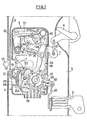
- the lock 1 shown in FIG. 1 is essentially housed in a parallelepipedic box 2 fixed flat in the edge of a door 3 of a motor vehicle provided on the one hand with an external control button 4 and with an internal control button (not shown ) for unlocking the lock, and on the other hand an external key 5 and a rod 6 connected to an interior frieze zipper (not shown) for its locking-unlocking.
- the lock will be described in its position shown in FIG. 1, which corresponds to its mounting on a front door of the vehicle.
- the housing 2 thus has a rectangular shape with its large vertical sides.
- the locking mechanism of the lock is mounted between two identical and parallel vertical plates 7 contained in the housing 2. It comprises an oscillating fork 8 forming a bolt, which pivots on a fixed horizontal axis 9, a pawl 10 and an opening lever 11 passing through a gasket seal that closes a slot in the housing 2.
- the fork 8 has the general shape of a cam disc provided with a roughly radial notch 12 which extends almost to the axis 9 and crosses a horizontal notch 13 of the plates 7 and of the rear face of the housing 2 in all the useful positions of the fork. More specifically, the fork 8 is made from a piece of steel in which the central hole and the notch 12 communicate, and the overmolding of a plastic lining around the periphery of the central hole and the notch separates these one from the other by a thin strip of plastic.
- the pawl 10 which is mounted oscillating on another horizontal axis 14 located on the other side of the notch 13 relative to the axis 9, that is to say above the notch 13, comprises a branch provided with a stop surface 15 and a retaining surface 16, and an actuating branch 17.
- a spring 18 biases clockwise the pawl towards its active position, in which the retaining surface 16 rests on an elastic stop 19.
- the lever 11 To move the pawl away from this position, the lever 11 must be tilted counterclockwise, which is articulated on the axis 14 and is biased towards its rest position by a spring 20. This tilting is effected either by means of the button 4, by means of a link 21, or by means of the interior control button, by means of a pull tab 22.
- the notch 12 directs its opening towards the entry of the notch 13.
- the pawl 10 is retracted and is supported by a concave surface 23 on a roughly circular surface 24, of maximum radius, of the fork 8 , spanning about a quarter of a turn.
- a cylindrical keeper 25 secured to the vehicle body enters the two notches 12 and 13 and rotates the fork 8 clockwise.
- the end of the surface 23 of the pawl comes in line with a first radial surface 26 of the fork, and, under the action of the spring 18, this surface comes to bear on a surface 27 of reduced but increasing diameter of the fork which extends to the notch 12.
- the surface 26 is then opposite the stop surface 15 of the pawl, which corresponds to the first locking notch of the lock.
- the locking-unlocking mechanism generally designated by the reference 32 and shown in FIGS. 1 and 3 to 5, essentially comprises an input lever 33, an actuating plate 34, a link 35 which ends in the tab 30 indicated above, and an actuator constituted by an electric motor or geared motor 36 received in a housing which projects from the front face of the housing 2, located in front of the plane of FIG. 1, and is an integral part of this housing.
- the lever 33 and the plate 34 are mounted oscillating on the same horizontal axis 37 near the lower right corner of the housing 2.
- the lever 33 comprises a disc 38 provided with an elastic metal blade 39 in a semicircle, and a tail 40 which leaves the housing through a lateral slot 41 of the latter and is connected to the barrel of the key 5 by a rod 42.
- the plate 34 (Fig. 1 and 3) has the general shape of an L whose angle, mounted on the axis 37, forms a disc 45 which receives the disc 38 of the lever 33.
- the vertical branch of the L ends by a toothed sector 46, and its horizontal branch by a screen 47 in an arc of a circle which permanently closes a lateral slot 48 of the housing 2 opposite to the slot 41.
- the lower end of the rod 6 is hung in the middle of this screen 47.
- the plate 34 has, on the side of the slot 41, a projecting peripheral flange 49 which runs along the vertical branch of the L and the disc 45. This flange is interrupted opposite the slot 41 and traversed at this location, with a notable circumferential clearance, by the tail 40 of the lever 33, which abuts against this edge in each of its stable positions.
- the output pinion 50 of the gear motor 36 is located in the housing 2 proper and meshes directly with the toothed sector 46 of the wafer 34.
- the link 35 carries the tab 30 at its upper end and is articulated by its lower end on a pivot 35A of the horizontal branch of the plate 34, so that the oscillation of this plate in a counterclockwise direction moves the link 35 towards the down and brings the tab 30 into its locking position, and vice versa (Fig. 2). Guiding in quasi-translation of the link 35 is provided on the one hand by the adjacent face of the pawl 10, on the other hand by an appropriate configuration of the housing 2.
- the lock also has a lever 51 for a door that is not closed properly (Fig. 1, 2 and 4).
- This lever is articulated by one end on a horizon axis tal 52 located between the notch 13 and the slot 48 of the housing 2 and bears elastically on the lower region of the fork 8 by its other bent end 53.
- This support is provided by the action of an elastic appendage 54 of the lever 51, the free end of which abuts on the upper edge of the slot 48.
- a metal blade 55 is fixed to the middle part of the lever 51. This blade, as the blade 39 of the lever 33, is applied elastically against a printed circuit board 56 (Fig. 1 and 5) carried by the large inner face of the housing 2.
- the operation of the locking mechanism 32 is as follows.
- the vehicle in question is equipped with several locks, for example four locks, at least two of which include a key 5. Any locks devoid of key, in particular on the rear doors, are identical to the others but may be devoid of the lever 33 and of the slot 41.
- the vehicle includes a centralized electrical distributor (not shown) which supplies all the motors 36 with electrical energy according to the orders it receives.
- Each printed circuit 56 is connected to the electrical distributor and to its poorly closed door indicator lamp (see below) by a bundle of cables terminated by a connector which clips onto the lower part of the housing 2.
- Dashboard switches or other parts of the vehicle can also give the central distributor various locking or unlocking orders, for example unlocking the locks when they are not all at their second closing notch.
- the plate 34 can also be maneuvered manually in one direction or the other by the rod 6, which attacks the end 47 of its horizontal branch.
- the blade 55 via the printed circuit 56, actuates a warning light located on the dashboard of the vehicle.
- the fork 8 turning clockwise, arrives in the second notch locking position (Fig. 2), the end 53 of the lever 51 rises on the ramp 58 and comes to rest on the surface 24, which extinguishes l door failure warning.
- the gear ratio of the electric actuator is chosen so that in the event of an electrical failure, the drive of the motor caused by the movement of the locking lever 33 requires an effort to maneuver the key 5 or the inner pull tab low enough to assure the user a pleasant functioning.
- the variant of FIG. 6 allows this manual drive of motor 36 to be completely eliminated.
- the lock 1A in FIG. 6 has the same locking-unlocking mechanism as the lock 1, and its locking mechanism 32A comprises the same locking rod 35. However, the lower end of this rod is directly articulated on a tail additional 59 of the lever 33 opposite the tail 40.
- the hinge pin 60 which is located as in the first embodiment, forms a cylindrical stud received in a groove 61 of a cam wheel 62 rotatably mounted in the housing 2. The outer periphery of this wheel is toothed and meshes with the output pinion 50 of the motor 36, which is then located in the region of the notch 13.
- the groove 61 comprises a spiral turn 63 whose two ends are joined by a radial line segment 64.
- each motor 36 rotates its wheel 62, which operates all the links 35, the radial faces 65 which terminate the spiral 63 limiting this rotation to one revolution, so that the position of the wheel 62 is identical with the lock locked and the lock unlocked.
- the time for changing the position of the locking mechanism by the motor 36 is of the order of half a second, that is to say of the same order of magnitude as the time required to turn a key 5 half a turn.
- the lever 33 is transformed into a monostable lever returned to a single stable position, which is an electrically inactive position.
- the corresponding lever is brought into an unstable position, which closes the circuit of all the motors 36 for the time necessary for the change of state of the locking mechanism.
- the key is released, the lever 33 returns to its neutral position, and the power supply to the motors 36 is interrupted. This eliminates the central distributor, at least as regards the simple locking-unlocking by key.
- the locking mechanism which is subjected to high stresses, is preferably made of steel, while the locking mechanism, subjected only to low stresses, can be essentially made of plastic.
- the screens 43 and 47 and the seal of the lever 11 ensure a good seal of the lock against dust and runoff water.
- each variant of the locking mechanism can be combined in the same lock housing with different types of locking-unlocking mechanisms.
Landscapes
- Lock And Its Accessories (AREA)
Applications Claiming Priority (2)
| Application Number | Priority Date | Filing Date | Title |
|---|---|---|---|
| FR8104172 | 1981-03-03 | ||
| FR8104172A FR2501271A1 (fr) | 1981-03-03 | 1981-03-03 | Serrure, notamment pour portiere de vehicule automobile |
Publications (2)
| Publication Number | Publication Date |
|---|---|
| EP0059658A1 EP0059658A1 (fr) | 1982-09-08 |
| EP0059658B1 true EP0059658B1 (fr) | 1985-05-15 |
Family
ID=9255797
Family Applications (1)
| Application Number | Title | Priority Date | Filing Date |
|---|---|---|---|
| EP82400277A Expired EP0059658B1 (fr) | 1981-03-03 | 1982-02-17 | Serrure, notamment pour portière de véhicule automobile |
Country Status (9)
| Country | Link |
|---|---|
| US (1) | US4452058A (show.php) |
| EP (1) | EP0059658B1 (show.php) |
| JP (1) | JPS57161281A (show.php) |
| BR (1) | BR8201084A (show.php) |
| CA (1) | CA1230235A (show.php) |
| DE (1) | DE3263487D1 (show.php) |
| ES (1) | ES264013Y (show.php) |
| FR (1) | FR2501271A1 (show.php) |
| MX (1) | MX157683A (show.php) |
Cited By (2)
| Publication number | Priority date | Publication date | Assignee | Title |
|---|---|---|---|---|
| DE3924231A1 (de) * | 1988-07-21 | 1990-02-01 | Aisin Seiki | Vorrichtung zur tuerverriegelung |
| DE10326141B4 (de) * | 2003-06-06 | 2005-11-17 | Kiekert Ag | Elektromechanische Baugruppe |
Families Citing this family (41)
| Publication number | Priority date | Publication date | Assignee | Title |
|---|---|---|---|---|
| DE3242527C3 (de) * | 1982-11-18 | 1995-09-07 | Neiman Sa | Schloß für eine Kraftfahrzeugtür |
| FR2542793B1 (fr) * | 1983-03-14 | 1985-07-19 | Mecanismes Comp Ind De | Serrure a ouverture electrique, notamment pour portieres de vehicules automobiles |
| JPS6083166U (ja) * | 1983-11-14 | 1985-06-08 | デルタ工業株式会社 | 自動車用ドアロツク装置 |
| FR2559535B1 (fr) * | 1984-02-13 | 1989-05-12 | Peugeot Aciers Et Outillage | Serrure pour portiere de vehicule automobile |
| JPS60174764U (ja) * | 1984-04-27 | 1985-11-19 | デルタ工業株式会社 | 自動車用ドアロツク装置 |
| US4685709A (en) * | 1984-05-29 | 1987-08-11 | R. R. Brink Locking Systems, Inc. | Deadlocked latch having disc and motor actuators |
| FR2586744B1 (fr) * | 1985-09-05 | 1987-12-04 | Mecanismes Comp Ind De | Serrure a ouverture et fermeture electriques, notamment pour portieres de vehicules automobiles |
| JPH07116876B2 (ja) * | 1985-12-18 | 1995-12-18 | 有限会社同栄企画センター | 自動車扉の施解錠方法および施解錠装置 |
| FR2592084B1 (fr) * | 1985-12-24 | 1988-03-25 | Mecanismes Comp Ind De | Actionneur de condamnation d'une serrure de porte de vehicule automobile |
| US4776619A (en) * | 1986-05-01 | 1988-10-11 | Southern Steel Company | Sliding door lock |
| US4763936A (en) * | 1986-10-20 | 1988-08-16 | General Motors Corporation | Power operated door latch |
| US4858452A (en) * | 1986-12-22 | 1989-08-22 | United Technologies Electro Systems, Inc. | Non-commutated linear motor |
| DE3725074C1 (de) * | 1987-07-29 | 1988-09-22 | Kiekert Gmbh Co Kg | Kraftfahrzeugtuerverschluss |
| JP2511115B2 (ja) * | 1988-07-21 | 1996-06-26 | アイシン精機株式会社 | ドアロツク装置 |
| CA1317776C (en) * | 1988-08-11 | 1993-05-18 | Shinjiro Yamada | Switching apparatus for vehicle locking device |
| JP2582178B2 (ja) * | 1990-07-19 | 1997-02-19 | 日産自動車株式会社 | フードロック装置 |
| JP2556789B2 (ja) * | 1991-03-29 | 1996-11-20 | 株式会社大井製作所 | 自動車用ドアロックの施解錠操作装置 |
| GB9108447D0 (en) * | 1991-04-19 | 1991-06-05 | Rockwell Automotive Body Syst | Vehicle door latches |
| DE4131891A1 (de) * | 1991-09-25 | 1993-04-01 | Bosch Gmbh Robert | Sperrvorrichtung fuer tueren eines kraftfahrzeugs |
| US5642636A (en) * | 1993-01-22 | 1997-07-01 | Mitsui Kinzoku Kogyo Kabushiki Kaisha | Locking device for trunk lids |
| JP2847461B2 (ja) * | 1993-07-05 | 1999-01-20 | 三井金属鉱業株式会社 | ドアロック装置におけるスイッチ機構 |
| JPH0828119A (ja) * | 1994-05-13 | 1996-01-30 | Nippondenso Co Ltd | ドアロック駆動装置 |
| JP2975536B2 (ja) * | 1994-08-01 | 1999-11-10 | 三井金属鉱業株式会社 | 車両ドアロック装置の制御方法 |
| DE29503683U1 (de) * | 1994-09-01 | 1995-05-18 | Kiekert AG, 42579 Heiligenhaus | Kraftfahrzeugtürverschluß |
| US5667263A (en) * | 1994-09-01 | 1997-09-16 | Kiekert Aktiengesellshaft | Power-actuated motor-vehicle door latch |
| GB2309251B (en) * | 1996-01-16 | 2000-05-17 | Nissan Europ Tech Centre | Electrical central locking arrangement |
| DE19636464A1 (de) * | 1996-09-07 | 1998-03-12 | Mannesmann Vdo Ag | Schließeinrichtung, insbesondere für Fahrzeugtüren oder dergleichen |
| WO1999000572A1 (en) * | 1997-06-26 | 1999-01-07 | Hyun Gyu Cho | Electric door latch and locking system of automobiles |
| FR2778195A1 (fr) * | 1998-04-30 | 1999-11-05 | Valeo Securite Habitacle | Serrure de porte de vehicule automobile a capotage |
| FR2781835B1 (fr) * | 1998-07-28 | 2001-01-05 | Coutier Moulage Gen Ind | Module de serrure electrique pour un coffre de vehicule |
| FR2782109B1 (fr) * | 1998-08-05 | 2001-09-28 | Valeo Securite Habitacle | Procede pour reduire la puissance necessaire a l'ouverture d'une serrure de porte et serrure pour la mise en oeuvre du procede |
| GB2344135B (en) * | 1998-11-25 | 2002-11-06 | Rover Group | A motor vehicle locking system |
| FR2794488A1 (fr) * | 1999-06-04 | 2000-12-08 | Valeo Securite Habitacle | Perfectionnement aux serrures, notamment pour vehicules automobiles |
| JP3773731B2 (ja) * | 1999-12-24 | 2006-05-10 | 株式会社大井製作所 | ドアロック装置 |
| KR100457127B1 (ko) * | 2002-06-01 | 2004-11-12 | 기아자동차주식회사 | 자동차의 도난 방지장치 |
| US7226112B2 (en) * | 2003-10-02 | 2007-06-05 | Nicholas Plastics Incorporated | Pinch warning and illumination system |
| EP2754799B1 (en) * | 2012-12-21 | 2017-03-08 | Magna Closures SpA | An electrical vehicle latch |
| JP6454907B2 (ja) * | 2014-07-18 | 2019-01-23 | 三井金属アクト株式会社 | 車両用ドアラッチ装置 |
| EP3253940A4 (en) * | 2015-02-02 | 2018-12-12 | Sargent and Greenleaf Inc. | Mechanical override of an electronic lock |
| US10392838B2 (en) * | 2015-06-11 | 2019-08-27 | Magna Closures Inc. | Key cylinder release mechanism for vehicle closure latches, latch assembly therewith and method of mechanically releasing a vehicle closure latch |
| US11519205B2 (en) * | 2018-05-14 | 2022-12-06 | Magna Closures Inc. | Closure latch assembly with power lock mechanism having outside lock lever water protection |
Citations (1)
| Publication number | Priority date | Publication date | Assignee | Title |
|---|---|---|---|---|
| US3157042A (en) * | 1963-03-29 | 1964-11-17 | Folger Adam | Motor-driven or operated locks, and the like |
Family Cites Families (5)
| Publication number | Priority date | Publication date | Assignee | Title |
|---|---|---|---|---|
| US2950138A (en) * | 1958-06-30 | 1960-08-23 | Gen Motors Corp | Closure latch |
| FR2115701A5 (show.php) * | 1970-11-30 | 1972-07-07 | Peugeot & Renault | |
| US3751088A (en) * | 1971-05-24 | 1973-08-07 | Schlage Lock Co | Electromagnetic lock |
| SE419255B (sv) * | 1975-11-08 | 1981-07-20 | Fichtel & Sachs Ag | Steng- och lasanordning vid fordon |
| DE2804613C2 (de) * | 1978-02-03 | 1983-03-31 | Daimler-Benz Ag, 7000 Stuttgart | Zentralverriegelungsvorrichtung für Drehfallenverschlüsse von Kraftfahrzeugtüren |
-
1981
- 1981-03-03 FR FR8104172A patent/FR2501271A1/fr active Granted
-
1982
- 1982-02-17 EP EP82400277A patent/EP0059658B1/fr not_active Expired
- 1982-02-17 DE DE8282400277T patent/DE3263487D1/de not_active Expired
- 1982-02-26 US US06/352,612 patent/US4452058A/en not_active Expired - Fee Related
- 1982-03-01 ES ES82264013U patent/ES264013Y/es not_active Expired
- 1982-03-02 CA CA000397415A patent/CA1230235A/en not_active Expired
- 1982-03-02 MX MX191633A patent/MX157683A/es unknown
- 1982-03-02 JP JP3372582A patent/JPS57161281A/ja active Pending
- 1982-03-02 BR BR8201084A patent/BR8201084A/pt not_active IP Right Cessation
Patent Citations (1)
| Publication number | Priority date | Publication date | Assignee | Title |
|---|---|---|---|---|
| US3157042A (en) * | 1963-03-29 | 1964-11-17 | Folger Adam | Motor-driven or operated locks, and the like |
Cited By (2)
| Publication number | Priority date | Publication date | Assignee | Title |
|---|---|---|---|---|
| DE3924231A1 (de) * | 1988-07-21 | 1990-02-01 | Aisin Seiki | Vorrichtung zur tuerverriegelung |
| DE10326141B4 (de) * | 2003-06-06 | 2005-11-17 | Kiekert Ag | Elektromechanische Baugruppe |
Also Published As
| Publication number | Publication date |
|---|---|
| JPS57161281A (en) | 1982-10-04 |
| US4452058A (en) | 1984-06-05 |
| ES264013Y (es) | 1983-05-01 |
| FR2501271B1 (show.php) | 1984-04-20 |
| EP0059658A1 (fr) | 1982-09-08 |
| DE3263487D1 (en) | 1985-06-20 |
| ES264013U (es) | 1982-11-16 |
| BR8201084A (pt) | 1983-01-11 |
| CA1230235A (en) | 1987-12-15 |
| MX157683A (es) | 1988-12-09 |
| FR2501271A1 (fr) | 1982-09-10 |
Similar Documents
| Publication | Publication Date | Title |
|---|---|---|
| EP0059658B1 (fr) | Serrure, notamment pour portière de véhicule automobile | |
| EP0215702B1 (fr) | Serrure à ouverture et fermeture électriques, notamment pour portières de véhicules automobiles | |
| EP0903457B1 (fr) | Serrure électrique pour portière de véhicule | |
| EP0113630A1 (fr) | Serrure, notamment pour portière de véhicule | |
| EP1030014A1 (fr) | Serrure en trois parties, pour ouvrant de véhicule automobile | |
| EP1030012B1 (fr) | Serrure pour ouvrant de véhicule automobile, à mémorisation de décondamnation | |
| FR2766861A1 (fr) | Serrure de porte de vehicule automobile a condamnation electrique | |
| EP0645511B1 (fr) | Serrure pour porte de véhicule automobile | |
| FR2768761A1 (fr) | Serrure electrique pour portiere de vehicule, comportant des moyens d'assistance a la fermeture et a l'ouverture | |
| FR2606450A1 (fr) | Serrure a actionnement electrique destinee a etre montee sur des vehicules automobiles | |
| EP1004731A1 (fr) | Serrure pour portière de véhicule automobile | |
| EP0095983B1 (fr) | Serrure, notamment pour véhicule automobile | |
| EP0095988B1 (fr) | Serrure de portière, notamment pour véhicule automobile | |
| EP1004727A1 (fr) | Serrure pour portière droite ou gauche de véhicule automobile | |
| EP0433103B1 (fr) | Dispositif de commande électrique d'un levier pivotant maintenu libre aux deux extrémités de sa course et serrure comportant ce dispositif | |
| EP0989266B1 (fr) | Serrure à décondamnation automatique à l'ouverture | |
| FR2906291A1 (fr) | Serrure motorisee a double came pour un volet ouvrant de vehicule automobile ou analogue. | |
| EP0102263B1 (fr) | Serrure à commande électrique pour portière de véhicule automobile | |
| EP0433104B1 (fr) | Mécanisme de débrayage de l'organe de verrouillage manuel associé à une serrure de portière de véhicule automobile et serrure le comportant | |
| FR2789718A1 (fr) | Serrure a condamnation enfant, pour ouvrant de vehicule automobile | |
| FR2783548A1 (fr) | Platine de servitude pour la commande des serrures d'un panneau ouvrant | |
| FR2635137A1 (fr) | Perfectionnements apportes aux serrures, notamment pour portieres de vehicules automobiles | |
| FR2521744A1 (fr) | Levier de commande perfectionne | |
| FR2773836A1 (fr) | Fermeture de porte de vehicule automobile | |
| EP1724422A1 (fr) | Mécanisme de commande de l'ouverture d'une portière de véhicule automobile |
Legal Events
| Date | Code | Title | Description |
|---|---|---|---|
| PUAI | Public reference made under article 153(3) epc to a published international application that has entered the european phase |
Free format text: ORIGINAL CODE: 0009012 |
|
| AK | Designated contracting states |
Designated state(s): DE GB IT SE |
|
| 17P | Request for examination filed |
Effective date: 19820910 |
|
| ITF | It: translation for a ep patent filed | ||
| ITF | It: translation for a ep patent filed | ||
| GRAA | (expected) grant |
Free format text: ORIGINAL CODE: 0009210 |
|
| AK | Designated contracting states |
Designated state(s): DE GB IT SE |
|
| REF | Corresponds to: |
Ref document number: 3263487 Country of ref document: DE Date of ref document: 19850620 |
|
| PLBE | No opposition filed within time limit |
Free format text: ORIGINAL CODE: 0009261 |
|
| STAA | Information on the status of an ep patent application or granted ep patent |
Free format text: STATUS: NO OPPOSITION FILED WITHIN TIME LIMIT |
|
| 26N | No opposition filed | ||
| ITTA | It: last paid annual fee | ||
| EAL | Se: european patent in force in sweden |
Ref document number: 82400277.8 |
|
| PGFP | Annual fee paid to national office [announced via postgrant information from national office to epo] |
Ref country code: SE Payment date: 19970220 Year of fee payment: 16 |
|
| PG25 | Lapsed in a contracting state [announced via postgrant information from national office to epo] |
Ref country code: SE Free format text: LAPSE BECAUSE OF NON-PAYMENT OF DUE FEES Effective date: 19980218 |
|
| EUG | Se: european patent has lapsed |
Ref document number: 82400277.8 |
|
| PGFP | Annual fee paid to national office [announced via postgrant information from national office to epo] |
Ref country code: GB Payment date: 20000211 Year of fee payment: 19 |
|
| PGFP | Annual fee paid to national office [announced via postgrant information from national office to epo] |
Ref country code: DE Payment date: 20000228 Year of fee payment: 19 |
|
| PG25 | Lapsed in a contracting state [announced via postgrant information from national office to epo] |
Ref country code: GB Free format text: LAPSE BECAUSE OF NON-PAYMENT OF DUE FEES Effective date: 20010217 |
|
| GBPC | Gb: european patent ceased through non-payment of renewal fee |
Effective date: 20010217 |
|
| PG25 | Lapsed in a contracting state [announced via postgrant information from national office to epo] |
Ref country code: DE Free format text: LAPSE BECAUSE OF NON-PAYMENT OF DUE FEES Effective date: 20011201 |