EP0057544A1 - Lageraufbau für Turbolader - Google Patents
Lageraufbau für Turbolader Download PDFInfo
- Publication number
- EP0057544A1 EP0057544A1 EP82300344A EP82300344A EP0057544A1 EP 0057544 A1 EP0057544 A1 EP 0057544A1 EP 82300344 A EP82300344 A EP 82300344A EP 82300344 A EP82300344 A EP 82300344A EP 0057544 A1 EP0057544 A1 EP 0057544A1
- Authority
- EP
- European Patent Office
- Prior art keywords
- peripheral portion
- inner peripheral
- bearing assembly
- floating
- length
- Prior art date
- Legal status (The legal status is an assumption and is not a legal conclusion. Google has not performed a legal analysis and makes no representation as to the accuracy of the status listed.)
- Granted
Links
Images
Classifications
-
- F—MECHANICAL ENGINEERING; LIGHTING; HEATING; WEAPONS; BLASTING
- F16—ENGINEERING ELEMENTS AND UNITS; GENERAL MEASURES FOR PRODUCING AND MAINTAINING EFFECTIVE FUNCTIONING OF MACHINES OR INSTALLATIONS; THERMAL INSULATION IN GENERAL
- F16C—SHAFTS; FLEXIBLE SHAFTS; ELEMENTS OR CRANKSHAFT MECHANISMS; ROTARY BODIES OTHER THAN GEARING ELEMENTS; BEARINGS
- F16C23/00—Bearings for exclusively rotary movement adjustable for aligning or positioning
- F16C23/02—Sliding-contact bearings
- F16C23/04—Sliding-contact bearings self-adjusting
- F16C23/041—Sliding-contact bearings self-adjusting with edge relief
-
- F—MECHANICAL ENGINEERING; LIGHTING; HEATING; WEAPONS; BLASTING
- F01—MACHINES OR ENGINES IN GENERAL; ENGINE PLANTS IN GENERAL; STEAM ENGINES
- F01D—NON-POSITIVE DISPLACEMENT MACHINES OR ENGINES, e.g. STEAM TURBINES
- F01D25/00—Component parts, details, or accessories, not provided for in, or of interest apart from, other groups
- F01D25/16—Arrangement of bearings; Supporting or mounting bearings in casings
- F01D25/162—Bearing supports
- F01D25/164—Flexible supports; Vibration damping means associated with the bearing
-
- F—MECHANICAL ENGINEERING; LIGHTING; HEATING; WEAPONS; BLASTING
- F16—ENGINEERING ELEMENTS AND UNITS; GENERAL MEASURES FOR PRODUCING AND MAINTAINING EFFECTIVE FUNCTIONING OF MACHINES OR INSTALLATIONS; THERMAL INSULATION IN GENERAL
- F16C—SHAFTS; FLEXIBLE SHAFTS; ELEMENTS OR CRANKSHAFT MECHANISMS; ROTARY BODIES OTHER THAN GEARING ELEMENTS; BEARINGS
- F16C17/00—Sliding-contact bearings for exclusively rotary movement
- F16C17/02—Sliding-contact bearings for exclusively rotary movement for radial load only
-
- F—MECHANICAL ENGINEERING; LIGHTING; HEATING; WEAPONS; BLASTING
- F16—ENGINEERING ELEMENTS AND UNITS; GENERAL MEASURES FOR PRODUCING AND MAINTAINING EFFECTIVE FUNCTIONING OF MACHINES OR INSTALLATIONS; THERMAL INSULATION IN GENERAL
- F16C—SHAFTS; FLEXIBLE SHAFTS; ELEMENTS OR CRANKSHAFT MECHANISMS; ROTARY BODIES OTHER THAN GEARING ELEMENTS; BEARINGS
- F16C17/00—Sliding-contact bearings for exclusively rotary movement
- F16C17/12—Sliding-contact bearings for exclusively rotary movement characterised by features not related to the direction of the load
- F16C17/18—Sliding-contact bearings for exclusively rotary movement characterised by features not related to the direction of the load with floating brasses or brushing, rotatable at a reduced speed
-
- F—MECHANICAL ENGINEERING; LIGHTING; HEATING; WEAPONS; BLASTING
- F16—ENGINEERING ELEMENTS AND UNITS; GENERAL MEASURES FOR PRODUCING AND MAINTAINING EFFECTIVE FUNCTIONING OF MACHINES OR INSTALLATIONS; THERMAL INSULATION IN GENERAL
- F16C—SHAFTS; FLEXIBLE SHAFTS; ELEMENTS OR CRANKSHAFT MECHANISMS; ROTARY BODIES OTHER THAN GEARING ELEMENTS; BEARINGS
- F16C2360/00—Engines or pumps
- F16C2360/23—Gas turbine engines
- F16C2360/24—Turbochargers
-
- Y—GENERAL TAGGING OF NEW TECHNOLOGICAL DEVELOPMENTS; GENERAL TAGGING OF CROSS-SECTIONAL TECHNOLOGIES SPANNING OVER SEVERAL SECTIONS OF THE IPC; TECHNICAL SUBJECTS COVERED BY FORMER USPC CROSS-REFERENCE ART COLLECTIONS [XRACs] AND DIGESTS
- Y10—TECHNICAL SUBJECTS COVERED BY FORMER USPC
- Y10S—TECHNICAL SUBJECTS COVERED BY FORMER USPC CROSS-REFERENCE ART COLLECTIONS [XRACs] AND DIGESTS
- Y10S384/00—Bearings
- Y10S384/90—Cooling or heating
- Y10S384/901—Floating bushing
Definitions
- This invention relates to bearing assemblies for journalling rotor shafts of high-speed rotary machines, particularly superchargers for automotive vehicles, and more particularly it is concerned with a bearing assembly of the floating bush type serving as a bearing for journalling the rotor shaft of a supercharger.
- a supercharger is provided with bearings for journalling a rotor shaft against a radial load and a thrust load applied thereto.
- Various types of bearing have been proposed for use as bearings for journalling the rotor shaft against a radial load.
- the main stay of the bearings used for this purpose nowadays is a bearing of the floating bush type, as shown in U.S. Patent No. 3,565,497, for example.
- the bearing of the floating bush type includes a floating bush interposed between the rotor shaft and a housing and restrained against movement axially of the rotor shaft by snap pins or other movement preventing means attached to the housing.
- the floating bush has a construction in which its inner peripheral portion positioned against the outer peripheral surface of the rotor shaft is of the same length as its outer peripheral portion.
- an object of the invention is to provide a supercharger bearing assembly suitable for use with a supercharger rotating at high speed.
- Another object is to provide a supercharger bearing assembly capable of reducing the amplitude of vibration thereof, reducing the loss of power due to a frictional loss and increasing resistance to seizure.
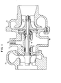
- Fig. 1 shows a supercharger incorporating therein one embodiment of the bearing assembly in conformity with the invention.
- a housing assembly includes an intermediate housing 1, a turbine housing 2 and a blower housing 3.
- a rotor shaft 4 has a turbine impeller 5 mounted at one end thereof and a blower impeller 6 mounted at the other end thereof and is journalled at its intermediate section by two floating bushes 7 interposed between the rotor shaft 4 and the intermediate housing 1.
- the floating bushes 7 are secured axially in place by retaining rings 8 attached to the intermediate housing 1.
- the floating bushes 7 receive a supply of lubricant through a lubricant inlet port 9 formed in the intermediate housing 1. After lubricating the floating bushes 7, the lubricant is discharged through a lubricant outlet port 10.
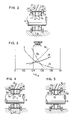
- the floating bushes 7 are, as shown in Fig. 2, each constructed such that an inner peripheral surface of the floating bush 7 is cut out in stepped fashion on opposite sides of an inner peripheral portion 7a as indicated at 11.
- the provision of the cutouts 11 on opposite sides of the inner peripheral portion 7a of the floating bush 7 enables the length Ll of the inner peripheral portion 7a to be smaller than the length L 2 of an outer peripheral portion 7b thereof.
- Fig. 4 shows a second embodiment of the bearing assembly in conformity with the invention.
- the bearing bush 7A is tapered as indicated at 12 on opposite sides of the inner peripheral portion 7a, so as to thereby reduce the length L 1 of the inner peripheral portion 7a of the floating bush 7A as compared with the length L 2 of the outer peripheral portion 7b thereof.
- the tapered portions 12 of the floating bush 7A have a centrifugal pumping function, so that the discharge of lubricant from the inner peripheral surface of the floating bush 7A can be promoted and a loss due to agitation can be avoided in this part. Thus overheating of the floating bush 7A can be avoided.
- Fig. 5 shows a third embodiment of the bearing assembly in conformity with the invention.
- tapered portions 13 formed on opposite sides of the inner peripheral portion 7b of the floating bush 7B extend from the inner peripheral surface near to the vicinity of the outer peripheral portion 7b on the outer peripheral surface of the floating bush 7B, to further promote the centrifugal pumping function performed by the tapered portions in draining the lubricant as compared with the embodiment shown in Fig. 4.
- the floating bushes 7, 7A, 7B have been shown and described as being secured in place by means of the retaining rings 8 to prevent their axial movement.
- the invention is not limited to this specific form of floating bush securing means and that any other suitable securing means may be used in the invention for securing the floating bushes 7, 7A, 7B in place.
- the bearing assembly provided with floating bushes according to the invention is capable of reducing vibration thereof, avoiding the loss of power due to a frictional loss and preventing scoring of the bearing, as compared with bearing assemblies provided with floating bushes of the prior art.
- the bearing assembly provided with floating bushes according to the invention has particular utility for use with high-speed rotary machines.
Landscapes
- Engineering & Computer Science (AREA)
- General Engineering & Computer Science (AREA)
- Mechanical Engineering (AREA)
- Sliding-Contact Bearings (AREA)
- Supercharger (AREA)
Applications Claiming Priority (2)
| Application Number | Priority Date | Filing Date | Title |
|---|---|---|---|
| JP56014353A JPS57129919A (en) | 1981-02-04 | 1981-02-04 | Floating bush bearing |
| JP14353/81 | 1981-02-04 |
Publications (2)
| Publication Number | Publication Date |
|---|---|
| EP0057544A1 true EP0057544A1 (de) | 1982-08-11 |
| EP0057544B1 EP0057544B1 (de) | 1985-01-16 |
Family
ID=11858699
Family Applications (1)
| Application Number | Title | Priority Date | Filing Date |
|---|---|---|---|
| EP82300344A Expired EP0057544B1 (de) | 1981-02-04 | 1982-01-22 | Lageraufbau für Turbolader |
Country Status (4)
| Country | Link |
|---|---|
| US (1) | US4640630A (de) |
| EP (1) | EP0057544B1 (de) |
| JP (1) | JPS57129919A (de) |
| DE (1) | DE3261868D1 (de) |
Cited By (3)
| Publication number | Priority date | Publication date | Assignee | Title |
|---|---|---|---|---|
| EP0141634A2 (de) * | 1983-10-29 | 1985-05-15 | Isuzu Motors Limited | Brennkraftmaschine mit Energiezurückgewinnungsanlage und Generator, welcher mit der Maschine einsetzbar ist |
| WO2008059371A3 (en) * | 2006-11-17 | 2008-11-27 | Toyota Motor Co Ltd | Bearing structure of turbocharger |
| DE102014208078A1 (de) * | 2014-04-29 | 2015-10-29 | Bosch Mahle Turbo Systems Gmbh & Co. Kg | Abgasturbolader mit einem Rotor |
Families Citing this family (23)
| Publication number | Priority date | Publication date | Assignee | Title |
|---|---|---|---|---|
| US4836758A (en) * | 1987-11-20 | 1989-06-06 | Copeland Corporation | Scroll compressor with canted drive busing surface |
| US5076765A (en) * | 1988-08-03 | 1991-12-31 | Nissan Motor Company, Altd. | Shaft seal arrangement of turbocharger |
| JP3924844B2 (ja) * | 1997-05-30 | 2007-06-06 | 石川島播磨重工業株式会社 | ターボチャージャのスラスト軸受構造 |
| GB0010542D0 (en) * | 2000-05-03 | 2000-06-21 | Dana Corp | Bearings |
| DE10311202A1 (de) * | 2003-03-14 | 2004-10-14 | Man B & W Diesel Ag | Lager für eine mit hoher Drehzahl umlaufende Welle |
| GB2405453B (en) * | 2003-08-27 | 2006-11-22 | Freepower Ltd | Bearing |
| US20080025658A1 (en) * | 2005-11-14 | 2008-01-31 | Brp-Rotax Gmbh & Co. Kg | Friction-bearing assembly for a rotating shaft |
| DE602006006524D1 (de) * | 2005-11-14 | 2009-06-10 | Brp Rotax Gmbh & Co Kg | Gleitlagereinrichtung für eine rotierende Welle |
| JP2009156333A (ja) * | 2007-12-26 | 2009-07-16 | Ihi Corp | 回転機械の軸受装置 |
| GB201002309D0 (en) * | 2010-02-11 | 2010-03-31 | Mahle Int Gmbh | Bearing |
| US9638059B2 (en) * | 2010-05-14 | 2017-05-02 | Borgwarner Inc. | Exhaust-gas turbocharger |
| DE102010052892A1 (de) * | 2010-12-01 | 2012-06-06 | Voith Patent Gmbh | Lageranordnung für eine Welle eines Turbinenrades |
| JP5705665B2 (ja) * | 2011-06-30 | 2015-04-22 | 三菱重工業株式会社 | ターボチャージャの軸受装置 |
| WO2013158358A1 (en) * | 2012-04-16 | 2013-10-24 | Borgwarner Inc. | Exhaust-gas turbocharger |
| DE102012208966A1 (de) * | 2012-05-29 | 2013-12-05 | Continental Automotive Gmbh | Abgasturbolader mit Schwimmbuchsenlager |
| JP6288885B2 (ja) * | 2014-08-28 | 2018-03-07 | 三菱重工業株式会社 | 軸受装置、及び回転機械 |
| US10375901B2 (en) | 2014-12-09 | 2019-08-13 | Mtd Products Inc | Blower/vacuum |
| JP6368864B2 (ja) * | 2015-09-14 | 2018-08-01 | 三菱重工エンジン&ターボチャージャ株式会社 | ターボチャージャ |
| DE102017126950A1 (de) * | 2017-11-16 | 2019-05-16 | Man Energy Solutions Se | Turbolader |
| US10557498B1 (en) * | 2018-10-12 | 2020-02-11 | Borgwarner Inc. | Full-floating bearing and turbocharger including the same |
| CN113454354A (zh) * | 2019-02-27 | 2021-09-28 | 三菱重工发动机和增压器株式会社 | 浮动衬套轴承以及增压器 |
| EP3875737B1 (de) * | 2020-03-03 | 2023-08-02 | Borgwarner Inc. | Lageranordnung für eine ladevorrichtung |
| EP3875738B1 (de) | 2020-03-03 | 2024-04-10 | Borgwarner Inc. | Lageranordnung für eine ladevorrichtung |
Citations (4)
| Publication number | Priority date | Publication date | Assignee | Title |
|---|---|---|---|---|
| DE349474C (de) * | 1918-12-24 | 1922-03-02 | John Platt | Wellen- oder Achsenlager |
| DE713099C (de) * | 1939-11-21 | 1941-10-31 | Mitteldeutsche Stahlwerke Akt | Aus zwei oder mehreren schwimmenden Buchsen gebildetes Lager |
| GB1003282A (en) * | 1960-09-26 | 1965-09-02 | Schwitzer Corp | Improvements in and relating to bearing structures |
| DE1950460U (de) * | 1961-12-09 | 1966-11-24 | Geraetebau Eberspaecher O H G | Lagerung fuer wellen. |
Family Cites Families (5)
| Publication number | Priority date | Publication date | Assignee | Title |
|---|---|---|---|---|
| US3058787A (en) * | 1959-06-22 | 1962-10-16 | Caterpillar Tractor Co | High speed shaft bearing lubrication |
| US3056634A (en) * | 1959-08-03 | 1962-10-02 | Schwitzer Corp | Bearing structure |
| US3494679A (en) * | 1968-01-30 | 1970-02-10 | Garrett Corp | Thrust bearing oil seal system |
| US3565497A (en) * | 1969-05-23 | 1971-02-23 | Caterpillar Tractor Co | Turbocharger seal assembly |
| JPS5565723A (en) * | 1978-11-14 | 1980-05-17 | Nissan Motor Co Ltd | Lubricating configuration of floating bush |
-
1981
- 1981-02-04 JP JP56014353A patent/JPS57129919A/ja active Pending
-
1982
- 1982-01-19 US US06/340,814 patent/US4640630A/en not_active Expired - Fee Related
- 1982-01-22 DE DE8282300344T patent/DE3261868D1/de not_active Expired
- 1982-01-22 EP EP82300344A patent/EP0057544B1/de not_active Expired
Patent Citations (4)
| Publication number | Priority date | Publication date | Assignee | Title |
|---|---|---|---|---|
| DE349474C (de) * | 1918-12-24 | 1922-03-02 | John Platt | Wellen- oder Achsenlager |
| DE713099C (de) * | 1939-11-21 | 1941-10-31 | Mitteldeutsche Stahlwerke Akt | Aus zwei oder mehreren schwimmenden Buchsen gebildetes Lager |
| GB1003282A (en) * | 1960-09-26 | 1965-09-02 | Schwitzer Corp | Improvements in and relating to bearing structures |
| DE1950460U (de) * | 1961-12-09 | 1966-11-24 | Geraetebau Eberspaecher O H G | Lagerung fuer wellen. |
Cited By (6)
| Publication number | Priority date | Publication date | Assignee | Title |
|---|---|---|---|---|
| EP0141634A2 (de) * | 1983-10-29 | 1985-05-15 | Isuzu Motors Limited | Brennkraftmaschine mit Energiezurückgewinnungsanlage und Generator, welcher mit der Maschine einsetzbar ist |
| EP0141634A3 (de) * | 1983-10-29 | 1986-07-30 | Isuzu Motors Limited | Brennkraftmaschine mit Energiezurückgewinnungsanlage und Generator, welcher mit der Maschine einsetzbar ist |
| US4694654A (en) * | 1983-10-29 | 1987-09-22 | Isuzu Motors Limited | Exhaust energy recovery and generator for use with an engine |
| WO2008059371A3 (en) * | 2006-11-17 | 2008-11-27 | Toyota Motor Co Ltd | Bearing structure of turbocharger |
| DE102014208078A1 (de) * | 2014-04-29 | 2015-10-29 | Bosch Mahle Turbo Systems Gmbh & Co. Kg | Abgasturbolader mit einem Rotor |
| US9677603B2 (en) | 2014-04-29 | 2017-06-13 | Bosch Mahle Turbo Systems Gmbh & Co. Kg | Exhaust gas turbocharger with a rotor |
Also Published As
| Publication number | Publication date |
|---|---|
| DE3261868D1 (en) | 1985-02-28 |
| EP0057544B1 (de) | 1985-01-16 |
| US4640630A (en) | 1987-02-03 |
| JPS57129919A (en) | 1982-08-12 |
Similar Documents
| Publication | Publication Date | Title |
|---|---|---|
| EP0057544B1 (de) | Lageraufbau für Turbolader | |
| US4874302A (en) | Scroll compressor with oil feeding passages in thrust bearing | |
| US3811741A (en) | Bearing | |
| US4427309A (en) | Turbocharger shaft bearing | |
| EP0272151B1 (de) | Lager- und Schmiersystem für einen Turbolader | |
| US4639148A (en) | Thrust bearing for turbocharger | |
| EP0395825A1 (de) | Lagereinheit für einen Turbolader | |
| CA1161484A (en) | Sleeve bearing | |
| DE112017004422T5 (de) | Modulare Turbokompressorwelle | |
| US3164422A (en) | Bearing lubricating and support assemblies for dynamoelectric machines | |
| US4488826A (en) | Offset wall bearing | |
| US4332427A (en) | Air bearing for use with concentric rotary shafts in machines | |
| JP2924481B2 (ja) | ターボチャージャのスラスト軸受装置 | |
| JPS6113018A (ja) | 傾動セグメント型ラジアル軸受 | |
| JP6469716B2 (ja) | 排気ガスターボチャージャーのための軸受装置および排気ガスターボチャージャー | |
| US4767265A (en) | Turbomolecular pump with improved bearing assembly | |
| US5451147A (en) | Turbo vacuum pump | |
| EP0147015A2 (de) | Molekularpumpe und Lager für diese | |
| JP3604110B2 (ja) | トルクコンバータのステータ | |
| JP4089209B2 (ja) | 両吸込み渦巻きポンプ | |
| JP2641703B2 (ja) | 排ガスターボ過給機の支承装置 | |
| EP3698059B1 (de) | Einteiliges buchsenlager für turbolader | |
| EP3698060A1 (de) | Turbolagersystem | |
| JP3657646B2 (ja) | ワンウェイクラッチ用ブシュ | |
| DE102020109516B4 (de) | Wasserpumpe mit anwendungsoptimiertem Aufbau |
Legal Events
| Date | Code | Title | Description |
|---|---|---|---|
| PUAI | Public reference made under article 153(3) epc to a published international application that has entered the european phase |
Free format text: ORIGINAL CODE: 0009012 |
|
| AK | Designated contracting states |
Designated state(s): DE FR GB |
|
| 17P | Request for examination filed |
Effective date: 19821207 |
|
| GRAA | (expected) grant |
Free format text: ORIGINAL CODE: 0009210 |
|
| AK | Designated contracting states |
Designated state(s): DE FR GB |
|
| REF | Corresponds to: |
Ref document number: 3261868 Country of ref document: DE Date of ref document: 19850228 |
|
| PGFP | Annual fee paid to national office [announced via postgrant information from national office to epo] |
Ref country code: DE Payment date: 19850329 Year of fee payment: 4 |
|
| ET | Fr: translation filed | ||
| PLBI | Opposition filed |
Free format text: ORIGINAL CODE: 0009260 |
|
| PLBI | Opposition filed |
Free format text: ORIGINAL CODE: 0009260 |
|
| PLBI | Opposition filed |
Free format text: ORIGINAL CODE: 0009260 |
|
| 26 | Opposition filed |
Opponent name: M.A.N. - B&W DIESEL GMBH Effective date: 19850808 |
|
| 26 | Opposition filed |
Opponent name: MTU MOTOREN- UND TURBINEN-UNION FRIEDRICHSHAFEN GM Effective date: 19850924 |
|
| 26 | Opposition filed |
Opponent name: AKTIENGESELLSCHAFT KUEHNLE, KOPP & KAUSCH Effective date: 19851014 |
|
| PG25 | Lapsed in a contracting state [announced via postgrant information from national office to epo] |
Ref country code: GB Effective date: 19860122 |
|
| RDAG | Patent revoked |
Free format text: ORIGINAL CODE: 0009271 |
|
| STAA | Information on the status of an ep patent application or granted ep patent |
Free format text: STATUS: PATENT REVOKED |
|
| 27W | Patent revoked |
Effective date: 19860311 |
|
| GBPC | Gb: european patent ceased through non-payment of renewal fee | ||
| GBPR | Gb: patent revoked under art. 102 of the ep convention designating the uk as contracting state | ||
| REG | Reference to a national code |
Ref country code: FR Ref legal event code: ST |