EP0057128B1 - Machine à substituer les traverses de voies ferrées et procédé d'utilisation - Google Patents
Machine à substituer les traverses de voies ferrées et procédé d'utilisation Download PDFInfo
- Publication number
- EP0057128B1 EP0057128B1 EP82400091A EP82400091A EP0057128B1 EP 0057128 B1 EP0057128 B1 EP 0057128B1 EP 82400091 A EP82400091 A EP 82400091A EP 82400091 A EP82400091 A EP 82400091A EP 0057128 B1 EP0057128 B1 EP 0057128B1
- Authority
- EP
- European Patent Office
- Prior art keywords
- clamp
- sleeper
- track
- sleepers
- machine according
- Prior art date
- Legal status (The legal status is an assumption and is not a legal conclusion. Google has not performed a legal analysis and makes no representation as to the accuracy of the status listed.)
- Expired
Links
- 238000000034 method Methods 0.000 title claims description 10
- 241001669679 Eleotris Species 0.000 claims abstract description 27
- 238000006073 displacement reaction Methods 0.000 claims description 10
- 238000000605 extraction Methods 0.000 description 8
- 238000006467 substitution reaction Methods 0.000 description 7
- 244000000231 Sesamum indicum Species 0.000 description 4
- 235000003434 Sesamum indicum Nutrition 0.000 description 4
- 244000185238 Lophostemon confertus Species 0.000 description 3
- 238000012423 maintenance Methods 0.000 description 3
- 240000008042 Zea mays Species 0.000 description 2
- 210000003323 beak Anatomy 0.000 description 2
- 239000003795 chemical substances by application Substances 0.000 description 2
- 238000009434 installation Methods 0.000 description 2
- 230000000284 resting effect Effects 0.000 description 2
- 244000251953 Agaricus brunnescens Species 0.000 description 1
- 235000001674 Agaricus brunnescens Nutrition 0.000 description 1
- 241000227645 Triplaris cumingiana Species 0.000 description 1
- 230000032683 aging Effects 0.000 description 1
- 230000006735 deficit Effects 0.000 description 1
- 230000008021 deposition Effects 0.000 description 1
- 230000000694 effects Effects 0.000 description 1
- 238000009432 framing Methods 0.000 description 1
- 238000002955 isolation Methods 0.000 description 1
- 238000010408 sweeping Methods 0.000 description 1
- 239000002023 wood Substances 0.000 description 1
Images


Classifications
-
- E—FIXED CONSTRUCTIONS
- E01—CONSTRUCTION OF ROADS, RAILWAYS, OR BRIDGES
- E01B—PERMANENT WAY; PERMANENT-WAY TOOLS; MACHINES FOR MAKING RAILWAYS OF ALL KINDS
- E01B29/00—Laying, rebuilding, or taking-up tracks; Tools or machines therefor
- E01B29/06—Transporting, laying, removing or renewing sleepers
- E01B29/09—Transporting, laying, removing or renewing sleepers under, or from under, installed rails
- E01B29/10—Transporting, laying, removing or renewing sleepers under, or from under, installed rails for inserting or removing sleepers
-
- E—FIXED CONSTRUCTIONS
- E01—CONSTRUCTION OF ROADS, RAILWAYS, OR BRIDGES
- E01B—PERMANENT WAY; PERMANENT-WAY TOOLS; MACHINES FOR MAKING RAILWAYS OF ALL KINDS
- E01B27/00—Placing, renewing, working, cleaning, or taking-up the ballast, with or without concurrent work on the track; Devices therefor; Packing sleepers
- E01B27/06—Renewing or cleaning the ballast in situ, with or without concurrent work on the track
- E01B27/11—Renewing or cleaning the ballast in situ, with or without concurrent work on the track combined with concurrent renewal of track components
Definitions
- the railroad superstructure is mainly made up of three elements of uneven longevity: the rails, the sleepers and the ballast.
- the effort to reduce track maintenance costs relates in particular to the search for better harmonization of the reliability specific to each of these three elements.
- the present invention therefore aims to create a machine capable of performing at high speed all the operations necessary for the replacement of wooden sleepers in particular by concrete sleepers, while keeping the track its perfect integrity.
- Such a machine is, in a known manner for example from AU-B-453 660, constituted by a wagon equipped with devices capable of individually replacing old sleepers with new sleepers, and in particular of a sleepers handling group comprising a set of gripping members which make it possible to grip a sleeper or a rail of the track, these members, suspended from a transverse beam and movable both in height as longitudinally and transversely with respect to the direction of the track, comprising a first member constituted by a clamp capable of gripping a cross member and of moving in a transverse direction from one side of the track substantially from a vertical plane passing through a first track rail, a second member and a third member capable of gripping each of one of the rails of the track to lift it, the first gripping member being able to move in transverse direction independently of the other two, while the latter can move together and have side spouts which are capable of to place themselves respectively under each of the rails of the track in order to lift them.
- the invention relates to a machine of this kind, further characterized in that the second gripping member, located between the first and the third and capable of gripping a rail, is, like the first gripping member, a clamp designed to grip a crosspiece, which can thus be gripped successively or simultaneously by a first clamp and by a second clamp, the latter being able to move in a transverse direction substantially in the space separating the vertical planes respectively containing the rails of the way.
- the first clamp evolves in the space located on one side of the track and the second clamp in the space located between the two rails of the track, while the third gripper can evolve in the space located on the other side of the track.
- the first clamp which is intended to perform the major part of the handling operations of the sleepers, should be able to be pivotally actuated around its vertical axis of symmetry, by at least a quarter of a turn so as to be able to '' bring the sleepers parallel to the track, which facilitates their routing on board the machine. It is also advantageous to ensure that the second clamp can move in the transverse direction independently of the third gripping member, so that the latter remains stationary while the second clamp moves transversely to ensure, as will be seen below. , the end of the operation of installing new sleepers.
- the transverse beam of the handling group is a telescopic beam formed of an inner tube, at the end of which is suspended the first clamp and which is movable by sliding in an outer tube connected to a slide able to move in height (thanks to a motor means) along a guide column fixed by its top to a carriage movable in longitudinal direction along guide rails integral with the chassis of the wagon, and along the outer tube can move on a short stroke a sliding part to which are suspended the second clamp and the third gripping member.
- the third member can be suspended directly from said sliding part in the region of its end facing outwards, the second being suspended by means of displacement in transverse direction.
- the amplitude of the transverse stroke which the first clamp and the second clamp can accomplish is preferably close to half the length of a cross member, while the short stroke to which the transverse displacements of the third gripping member can be limited is about the width of a rail shoe.
- a machine according to the invention may advantageously further comprise an earthmoving group comprising a clamshell movable in height and in the longitudinal direction and designed to allow the removal and replacement of the ballast surrounding the crosspiece to be replaced, which leads to fully mechanical handling of the ballast.
- an earthmoving group comprising a clamshell movable in height and in the longitudinal direction and designed to allow the removal and replacement of the ballast surrounding the crosspiece to be replaced, which leads to fully mechanical handling of the ballast.
- this clamshell is subdivided into three parts separated by two intervals forming free spaces where the rails of the track are inscribed when the grab is lowered in contact with the ballast, so that the latter can work on both sides other rails along the entire length of the sleepers.
- the clamshell should be subject to the curvature of the track by giving it the possibility of moving in a transverse direction under the action of a guide means maintaining said free spaces facing the rails of the track.
- the clamshell can be suspended by articulated bars forming a deformable parallelogram located in a transverse plane, these bars being attached to a carriage movable in the longitudinal direction, preferably moving on the same rails as the carriage of the group of handling.
- a machine preferably has a double conveyor, namely a conveyor for removing old sleepers and a conveyor for supplying new sleepers. , both accessible to the first clamp of the handling group.
- This arrangement allows direct new sleepers to be brought ment of a flat wagon coupled to the machine and to evacuate the old sleepers towards it.
- the machine should be equipped with a ballast reserve hopper, so as to be able to dump transversely to the track any quantity of additional ballast necessary to properly stuff the crossbar just installed, with a tamping group. ballast under this crosspiece and finally a leveling brush box to sweep and remove the excess ballast.
- the various movements and displacements of the movable members which it comprises should be obtained by means of motors or jacks, preferably hydraulic, controlled from a control (of course with the exception of the transverse movements of the clamshell bucket of the earthworks, which depend solely on the aforementioned means of guidance on the rails).
- the invention also relates to a method of handling sleepers during substitution operations using a machine as described above.
- This process is in particular characterized by the fact that, after removal of a crosspiece to be replaced, the installation of a new crosspiece takes place in two phases, namely a first phase where the crosspiece, captured in its central region by the first clamp is slid by the latter under the first rail of the track until said clamp is stopped by said rail, and a second phase where the crosspiece, released from the first clamp, is gripped in its central region by the second clamp beyond said rail, the latter clamp completing the positioning of the cross member under the rails of the track.
- This operating mode authorized by the machine according to the invention, is of great importance.
- the new sleepers are grasped and always pulled by their central region, which eliminates this drawback and thus avoids any deformation of the track.
- the removal of an old crosspiece to be replaced it is carried out by means of the first clamp preferably in two successive extraction phases, in each of which the crosspiece is pulled by this clamp of approximately half its length. A transverse stroke of reduced amplitude is therefore sufficient for this clamp, which simplifies the design of the machine.
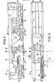
- Wagon 31 is self-propelled thanks to a propulsion assembly, not shown.
- the handling group 38 comprises a telescopic transverse beam 51 carrying the three clamps 39, 40 and 41 mentioned above and formed of an outer tube 52 of square section and of a inner tube 53 also of square section, capable of moving by sliding in the tube 52 under the action of a long jack 54.
- the tube 52 is fixed to a slide 55 which can move, by means of a motor means not shown, along a vertical column 56 of circular section, which is suspended from a carriage 57 movable in the longitudinal direction of the wagon 31 in guide rails 58 integral with the side members 33.
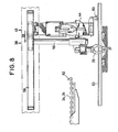
- the clamp 39 is fixed under the end of the tube 53 emerging from the tube 52, by means of a motorized connecting member 59 enabling it to rotate a quarter of a turn, in one direction or the other, around its vertical axis of symmetry.
- the clamps 40 and 41 are carried by a sliding part 60 capable of moving, over a short stroke, thanks to a jack 61, below and along the tube 52 to which it is suspended by rollers resting on wings 62 which the tube 52 offers laterally.
- the clamp 41 is suspended at one end of the movable part 60 close to the end of the tube 53 opposite that to which the clamp 39 is suspended.
- the clamp 40 is suspended from said part 60 , between the clamps 39 and 41, by means of a translation means constituted by a rotating threaded rod 29 and a nut 30 through which the latter passes, which is mounted under the part 60 parallel to the longitudinal direction of the latter and tubes 52 and 53 forming the telescopic beam 51.
- the clamps 39, 40 and 41 can move in the three directions of space; more precisely, all of said clamps are movable relative to the chassis of the wagon 31, longitudinally by displacement of the carriage 57 along the rails 58, vertically by displacement of the slide 55 along the column 56 and transversely, respectively by sliding of the tube 53 in the tube 52 for the clamp 39, by displacement of the part 60 for the clamps 40 and 41 and, moreover for the clamp 40, by rotation of the threaded rod 29.
- said clamps are each provided with 'an actuating means at the opening and closing of their branches. However, one can dispense with providing such an actuating means the clamp 41, because, as will be seen, unlike the other clamps 39 and 40, it is not used to grip the crosspieces, so that its branches can remain stationary when open.
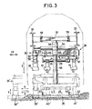
- Figure 3 shows the clamps 39, 40 and 41 in the initial position, in which the clamps 39 and 41 are located above the sleeper heads of the track 42, therefore on either side of the rails 63, 64 of that -this, while the clamp 40 overhangs the space between these rails, the clamps 40 and 41 lying directly above areas respectively of the rail 63 and of the rail 64 of the track 42 and located on the same side relative to these rails (to the right of these in Figure 3).
- This is provided so that the clamps 40 and 41, distant by a length equal to the spacing of the rails 63, 64 of the track, can be introduced together under these rails by nozzles 81 which their articulated branches present laterally, in view raise track 42.
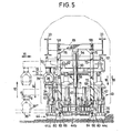
- the earthmoving group 43 (FIGS. 4 and 5) is suspended from a carriage 65 movable in longitudinal direction, like the carriage 57, along the guide rails 58.
- Its clamshell bucket 44 is subdivided into three parts 44a, 44b and 44c making two free intervals 66 appear corresponding to the location of the rails 63, 64 of the track 42.
- the jaws of this multiple bucket which makes it possible to carry out transverse earthwork of the ballast in a single operation, despite the presence of the rails, are actuated by four jacks 67 by means of articulated rods 68.
- the pivot axis 69 of the jaws of the bucket is supported by vertical plates 70 welded to a common transverse plate 71, to which are also welded sleeves 72 sliding on guide bars 73 during movements in height of this plate 71 and of the bucket 44 under the action of a jack 74 connecting the carriage 65 and the pivot axis 69 of the jaws of the bucket.
- the guide bars 73 are articulated on the one hand to the carriage 65 at 75 and on the other hand at 76 to parts 77 connected by a horizontal rod 78 so as to form a deformable parallelogram in transverse direction.
- articulated arms 79 carrying small liftable wheels 80 which, applied to the rails 63, 64 of the track 42 and guided by them, cause the aforementioned parallelogram to deform in the event of a curve in the track, so that the bucket 44 is offset transversely by the desired quantity so that the intervals 66 between the parts which compose it always remain in line with the rails 63, 64.
- the jack 74 is arranged parallel to the bars 73 and articulated like them at its ends.
- the wagon is further advanced so as to be able to successively actuate the tamping group 48 and the adjustment brush box 49 in the region surrounding the cross member 37.
- the extraction or introduction of the sleepers can be done either on the side of the runway or on the side of the cross-section, by simply inverting the handling group 38 around the column 56.
Landscapes
- Engineering & Computer Science (AREA)
- Architecture (AREA)
- Civil Engineering (AREA)
- Structural Engineering (AREA)
- Machines For Laying And Maintaining Railways (AREA)
Priority Applications (1)
| Application Number | Priority Date | Filing Date | Title |
|---|---|---|---|
| AT82400091T ATE7613T1 (de) | 1981-01-22 | 1982-01-18 | Vorrichtung zum auswechseln von schwellen bei eisenbahngleisen und verfahren zur benutzung dieser vorrichtung. |
Applications Claiming Priority (2)
| Application Number | Priority Date | Filing Date | Title |
|---|---|---|---|
| FR8101128A FR2498220A1 (fr) | 1981-01-22 | 1981-01-22 | Machine a substituer les traverses de voies ferrees et procede d'utilisation |
| FR8101128 | 1981-01-22 |
Publications (2)
| Publication Number | Publication Date |
|---|---|
| EP0057128A1 EP0057128A1 (fr) | 1982-08-04 |
| EP0057128B1 true EP0057128B1 (fr) | 1984-05-23 |
Family
ID=9254391
Family Applications (1)
| Application Number | Title | Priority Date | Filing Date |
|---|---|---|---|
| EP82400091A Expired EP0057128B1 (fr) | 1981-01-22 | 1982-01-18 | Machine à substituer les traverses de voies ferrées et procédé d'utilisation |
Country Status (4)
| Country | Link |
|---|---|
| EP (1) | EP0057128B1 (OSRAM) |
| AT (1) | ATE7613T1 (OSRAM) |
| DE (1) | DE3260165D1 (OSRAM) |
| FR (1) | FR2498220A1 (OSRAM) |
Cited By (3)
| Publication number | Priority date | Publication date | Assignee | Title |
|---|---|---|---|---|
| DE3634399A1 (de) * | 1986-02-12 | 1987-08-13 | Plasser Bahnbaumasch Franz | Gleisstopfmaschine mit hebe-, stopf- und gegebenenfalls richtaggregat |
| AT398592B (de) * | 1992-02-19 | 1994-12-27 | Plasser Bahnbaumasch Franz | Verladewagen zum aufnehmen, weitertransportieren und abwerfen von schüttgut |
| WO2015024626A1 (de) | 2013-08-20 | 2015-02-26 | Matisa Materiel Industriel Sa | Verfahren zur erneuerung von schwellen und schotter unter dem angehobenen schienenstrang |
Families Citing this family (16)
| Publication number | Priority date | Publication date | Assignee | Title |
|---|---|---|---|---|
| IT1210796B (it) * | 1987-06-08 | 1989-09-20 | Enrico Valditerra | Convoglio di rinnovamento di strade ferrate con mezzi di sostituzione totale o parziale delle traverse disostegno dei binari |
| AT391501B (de) * | 1987-07-23 | 1990-10-25 | Plasser Bahnbaumasch Franz | Gleisstopfmaschine |
| DE3814733C2 (de) * | 1987-07-23 | 1998-10-22 | Plasser Bahnbaumasch Franz | Gleisstopfmaschine |
| AT389541B (de) * | 1987-07-23 | 1989-12-27 | Plasser Bahnbaumasch Franz | Schwellenauswechsel-maschine |
| AT391335B (de) * | 1988-03-08 | 1990-09-25 | Plasser Bahnbaumasch Franz | Gleisstopfmaschine |
| AT400341B (de) * | 1990-08-24 | 1995-12-27 | Plasser Bahnbaumasch Franz | Maschine zum schwellenwechseln |
| AT400729B (de) * | 1990-08-24 | 1996-03-25 | Plasser Bahnbaumasch Franz | Maschine zum austauschen der schwellen eines gleises |
| US5063856A (en) * | 1990-10-16 | 1991-11-12 | Franz Plasser Bahnbaumaschinen-Industriegesellschaft M.B.H. | Machine for picking up tie plates |
| US5937763A (en) * | 1996-04-23 | 1999-08-17 | Franz Plasser Bahnbaumaschinen-Industriegesellschaft M.B.H. | Machine and method of distributing ballast |
| AT7113U3 (de) * | 2004-06-07 | 2005-07-25 | Plasser Bahnbaumasch Franz | Verfahren zum ersetzen von schadhaften schwellen eines gleises und maschine |
| RU2378441C1 (ru) * | 2008-06-24 | 2010-01-10 | ЗАО "Центральное конструкторское бюро тяжелых путевых машин" | Машина локальной выправки пути |
| AT510423B1 (de) * | 2011-01-11 | 2012-04-15 | Franz Plasser Bahnbaumaschinen-Industriegesellscha | Verfahren und fahrzeug zum abschnittsweisen ersatz von altschwellen eines gleises durch neuschwellen |
| FR2998591B1 (fr) * | 2012-11-23 | 2014-12-19 | Europ De Travaux Ferroviaires Etf | Procede de renouvellement de voie et ballast a haut rendement. |
| CN107178015A (zh) * | 2017-07-06 | 2017-09-19 | 中铁上海工程局集团有限公司 | 一种钢梁明桥面合成树脂长轨枕更换施工装置及方法 |
| CN108263970A (zh) * | 2018-02-07 | 2018-07-10 | 北京好运达智创科技有限公司 | 水泥轨枕入蒸养双轨平移吊车 |
| CN117166298A (zh) * | 2023-08-16 | 2023-12-05 | 中铁宝桥集团有限公司 | 一种跨坐式单轨道岔尾轴的更换装置及方法 |
Family Cites Families (3)
| Publication number | Priority date | Publication date | Assignee | Title |
|---|---|---|---|---|
| AU453660B2 (en) * | 1970-10-09 | 1974-09-20 | Aresco Trak-Chief Proprietary Limited | Railroad tie renewing and crib scarifying machine |
| US3675580A (en) * | 1971-01-18 | 1972-07-11 | Kershaw Mfg Co Inc | Apparatus for replacing old cross tie with new cross tie |
| AT359111B (de) * | 1977-10-04 | 1980-10-27 | Plasser Bahnbaumasch Franz | Maschinenanordnung zum bearbeiten des gleises, insbesondere mit einer schotterbett- -reinigungsmaschine |
-
1981
- 1981-01-22 FR FR8101128A patent/FR2498220A1/fr active Granted
-
1982
- 1982-01-18 AT AT82400091T patent/ATE7613T1/de not_active IP Right Cessation
- 1982-01-18 DE DE8282400091T patent/DE3260165D1/de not_active Expired
- 1982-01-18 EP EP82400091A patent/EP0057128B1/fr not_active Expired
Cited By (3)
| Publication number | Priority date | Publication date | Assignee | Title |
|---|---|---|---|---|
| DE3634399A1 (de) * | 1986-02-12 | 1987-08-13 | Plasser Bahnbaumasch Franz | Gleisstopfmaschine mit hebe-, stopf- und gegebenenfalls richtaggregat |
| AT398592B (de) * | 1992-02-19 | 1994-12-27 | Plasser Bahnbaumasch Franz | Verladewagen zum aufnehmen, weitertransportieren und abwerfen von schüttgut |
| WO2015024626A1 (de) | 2013-08-20 | 2015-02-26 | Matisa Materiel Industriel Sa | Verfahren zur erneuerung von schwellen und schotter unter dem angehobenen schienenstrang |
Also Published As
| Publication number | Publication date |
|---|---|
| EP0057128A1 (fr) | 1982-08-04 |
| FR2498220A1 (fr) | 1982-07-23 |
| ATE7613T1 (de) | 1984-06-15 |
| DE3260165D1 (en) | 1984-06-28 |
| FR2498220B1 (OSRAM) | 1983-08-12 |
Similar Documents
| Publication | Publication Date | Title |
|---|---|---|
| EP0057128B1 (fr) | Machine à substituer les traverses de voies ferrées et procédé d'utilisation | |
| EP0004985B1 (fr) | Train de renouvellement d'une voie de chemin de fer | |
| EP2091677B1 (fr) | Installation support pour la fabrication d'armatures metalliques et son procede de mise en oeuvre | |
| FR2713679A1 (fr) | Train de travaux pour remplacer des traverses anciennes d'une voie ferrée par des traverses neuves et procédé pour la mise en Óoeuvre de celui-ci . | |
| FR2558859A1 (fr) | Procede et machine pour le nettoyage d'un lit de ballast de voie de chemin de fer | |
| FR2618466A1 (fr) | Machine d'echange de traverses | |
| FR2666103A1 (fr) | Machine pour le remplacement de traverses. | |
| EP0355240A1 (fr) | Train de renouvellement d'une voie de chemin de fer | |
| FR2666102A1 (fr) | Machine pour le remplacement des traverses d'une voie ferree. | |
| FR2667883A1 (fr) | Machine de ramassage de selles nervurees d'une voie ferree. | |
| EP0505240A1 (fr) | Installation pour la pose et la substitution d'éléments de construction de voie ferrée et procédé utilisant cette installation | |
| FR2706348A1 (fr) | Unité de sciage de blocs de matériau tel que pierre, marbre, granit. | |
| FR2562572A1 (fr) | Installation roulante et procede pour la reception et/ou la pose de travees de voie ferree | |
| FR2683837A1 (fr) | Structure de travure destinee en particulier au franchissement de breches par des vehicules et systeme de transport et de depose de la structure. | |
| EP0061227A1 (fr) | Régaleuse à ballast mobile sur voie | |
| FR2535359A1 (fr) | Procede de remplacement de voies ferrees et cadre de manutention pour sa mise en oeuvre | |
| FR2777024A1 (fr) | Machine comportant un dispositif de deblayage de cases entre-traverses | |
| EP0467001B1 (fr) | Train de pose des nouvelles voies ferrées et procédé pour la pose de celles-ci utilisant un tel train | |
| EP0160898B1 (fr) | Appareil de manutention d'un panneau d'appareil de voie ferrée | |
| FR2741024A1 (fr) | Plate-forme mobile pour le franchissement de denivellations en degre | |
| FR2695328A1 (fr) | Installation de triage pour matériel en long, en particulier bois de sciage. | |
| FR2476513A1 (fr) | Installation de coulee continue verticale et procede d'exploitation de cette installation | |
| FR2666358A1 (fr) | Procede et machine de traitement de voie ferree. | |
| FR2649638A2 (fr) | Chaine de production automatique de poutres coffrantes en beton arme pour planchers-dalles | |
| FR2542775A1 (fr) | Machine de chantier ferroviaire pour la saisie et le portage de troncons et/ou d'appareils de voie montes |
Legal Events
| Date | Code | Title | Description |
|---|---|---|---|
| PUAI | Public reference made under article 153(3) epc to a published international application that has entered the european phase |
Free format text: ORIGINAL CODE: 0009012 |
|
| 17P | Request for examination filed |
Effective date: 19820119 |
|
| AK | Designated contracting states |
Designated state(s): AT BE CH DE GB IT LU NL SE |
|
| ITCL | It: translation for ep claims filed |
Representative=s name: BARZANO' E ZANARDO MILANO S.P.A. |
|
| TCAT | At: translation of patent claims filed | ||
| ITF | It: translation for a ep patent filed | ||
| GRAA | (expected) grant |
Free format text: ORIGINAL CODE: 0009210 |
|
| AK | Designated contracting states |
Designated state(s): AT BE CH DE GB IT LI LU NL SE |
|
| REF | Corresponds to: |
Ref document number: 7613 Country of ref document: AT Date of ref document: 19840615 Kind code of ref document: T |
|
| REF | Corresponds to: |
Ref document number: 3260165 Country of ref document: DE Date of ref document: 19840628 |
|
| PLBE | No opposition filed within time limit |
Free format text: ORIGINAL CODE: 0009261 |
|
| STAA | Information on the status of an ep patent application or granted ep patent |
Free format text: STATUS: NO OPPOSITION FILED WITHIN TIME LIMIT |
|
| 26N | No opposition filed | ||
| ITTA | It: last paid annual fee | ||
| PGFP | Annual fee paid to national office [announced via postgrant information from national office to epo] |
Ref country code: NL Payment date: 19930131 Year of fee payment: 12 |
|
| PGFP | Annual fee paid to national office [announced via postgrant information from national office to epo] |
Ref country code: CH Payment date: 19930709 Year of fee payment: 12 |
|
| PGFP | Annual fee paid to national office [announced via postgrant information from national office to epo] |
Ref country code: DE Payment date: 19930712 Year of fee payment: 12 |
|
| PGFP | Annual fee paid to national office [announced via postgrant information from national office to epo] |
Ref country code: SE Payment date: 19930713 Year of fee payment: 12 Ref country code: GB Payment date: 19930713 Year of fee payment: 12 |
|
| PGFP | Annual fee paid to national office [announced via postgrant information from national office to epo] |
Ref country code: AT Payment date: 19930720 Year of fee payment: 12 |
|
| PGFP | Annual fee paid to national office [announced via postgrant information from national office to epo] |
Ref country code: LU Payment date: 19930730 Year of fee payment: 12 |
|
| PGFP | Annual fee paid to national office [announced via postgrant information from national office to epo] |
Ref country code: BE Payment date: 19930803 Year of fee payment: 12 |
|
| EPTA | Lu: last paid annual fee | ||
| PG25 | Lapsed in a contracting state [announced via postgrant information from national office to epo] |
Ref country code: LU Free format text: LAPSE BECAUSE OF NON-PAYMENT OF DUE FEES Effective date: 19940118 Ref country code: GB Effective date: 19940118 Ref country code: AT Effective date: 19940118 |
|
| PG25 | Lapsed in a contracting state [announced via postgrant information from national office to epo] |
Ref country code: SE Effective date: 19940119 |
|
| PG25 | Lapsed in a contracting state [announced via postgrant information from national office to epo] |
Ref country code: LI Effective date: 19940131 Ref country code: CH Effective date: 19940131 Ref country code: BE Effective date: 19940131 |
|
| BERE | Be: lapsed |
Owner name: SOTRAMEF Effective date: 19940131 |
|
| PG25 | Lapsed in a contracting state [announced via postgrant information from national office to epo] |
Ref country code: NL Effective date: 19940801 |
|
| GBPC | Gb: european patent ceased through non-payment of renewal fee |
Effective date: 19940118 |
|
| NLV4 | Nl: lapsed or anulled due to non-payment of the annual fee | ||
| REG | Reference to a national code |
Ref country code: CH Ref legal event code: PL Ref country code: CH Ref legal event code: AUV Free format text: LE BREVET CI-DESSUS EST TOMBE EN DECHEANCE, FAUTE DE PAIEMENT, DE LA 13E ANNUITE. |
|
| PG25 | Lapsed in a contracting state [announced via postgrant information from national office to epo] |
Ref country code: DE Effective date: 19941001 |
|
| EUG | Se: european patent has lapsed |
Ref document number: 82400091.3 Effective date: 19940810 |