EP0056712A2 - Informationsleseeinrichtung mit Nachführsystem - Google Patents
Informationsleseeinrichtung mit Nachführsystem Download PDFInfo
- Publication number
- EP0056712A2 EP0056712A2 EP82300203A EP82300203A EP0056712A2 EP 0056712 A2 EP0056712 A2 EP 0056712A2 EP 82300203 A EP82300203 A EP 82300203A EP 82300203 A EP82300203 A EP 82300203A EP 0056712 A2 EP0056712 A2 EP 0056712A2
- Authority
- EP
- European Patent Office
- Prior art keywords
- closed loop
- information
- control circuit
- read head
- operatively coupled
- Prior art date
- Legal status (The legal status is an assumption and is not a legal conclusion. Google has not performed a legal analysis and makes no representation as to the accuracy of the status listed.)
- Granted
Links
- 230000003287 optical effect Effects 0.000 claims description 19
- 230000001360 synchronised effect Effects 0.000 claims description 9
- 238000001514 detection method Methods 0.000 abstract description 8
- 238000013016 damping Methods 0.000 abstract description 2
- 238000000034 method Methods 0.000 description 18
- 238000010586 diagram Methods 0.000 description 12
- 230000007547 defect Effects 0.000 description 4
- 230000008569 process Effects 0.000 description 2
- 230000004075 alteration Effects 0.000 description 1
- 230000008859 change Effects 0.000 description 1
- 238000006073 displacement reaction Methods 0.000 description 1
- 238000012986 modification Methods 0.000 description 1
- 230000004048 modification Effects 0.000 description 1
- ORQBXQOJMQIAOY-UHFFFAOYSA-N nobelium Chemical compound [No] ORQBXQOJMQIAOY-UHFFFAOYSA-N 0.000 description 1
- 230000009467 reduction Effects 0.000 description 1
- 230000002441 reversible effect Effects 0.000 description 1
Images


Classifications
-
- G—PHYSICS
- G11—INFORMATION STORAGE
- G11B—INFORMATION STORAGE BASED ON RELATIVE MOVEMENT BETWEEN RECORD CARRIER AND TRANSDUCER
- G11B21/00—Head arrangements not specific to the method of recording or reproducing
- G11B21/02—Driving or moving of heads
- G11B21/10—Track finding or aligning by moving the head ; Provisions for maintaining alignment of the head relative to the track during transducing operation, i.e. track following
-
- G—PHYSICS
- G11—INFORMATION STORAGE
- G11B—INFORMATION STORAGE BASED ON RELATIVE MOVEMENT BETWEEN RECORD CARRIER AND TRANSDUCER
- G11B7/00—Recording or reproducing by optical means, e.g. recording using a thermal beam of optical radiation by modifying optical properties or the physical structure, reproducing using an optical beam at lower power by sensing optical properties; Record carriers therefor
- G11B7/08—Disposition or mounting of heads or light sources relatively to record carriers
- G11B7/09—Disposition or mounting of heads or light sources relatively to record carriers with provision for moving the light beam or focus plane for the purpose of maintaining alignment of the light beam relative to the record carrier during transducing operation, e.g. to compensate for surface irregularities of the latter or for track following
- G11B7/0901—Disposition or mounting of heads or light sources relatively to record carriers with provision for moving the light beam or focus plane for the purpose of maintaining alignment of the light beam relative to the record carrier during transducing operation, e.g. to compensate for surface irregularities of the latter or for track following for track following only
- G11B7/0904—Dithered tracking systems
Definitions
- This invention relates to an information read apparatus for reading information tracks in an information plane of an information carrier, with the aid of a tracking control system, and more in particular with the aid of a tracking control system comprising a first closed loop for high speed control, and a second closed loop for high precision control.
- Tracking control systems which usually consist of single closed loops need means for detecting tracking error.
- a differential method and a wobbling method are both well known as said means for detecting tracking error.
- Said differential method is typical.
- a tracking error is detected differentially by plural detectors.
- This method is very simple and easy, but has the defect that the detected tracking error signal inherently tends to include low frequency (or DC) noises.
- said detectors detect a variation of some physical value caused'by a tracking error instead of detecting the tracking error directly.
- said detected value does not always precisely coincide with the tracking error.
- the tracking error signal is so small that the tracking control is disturbed by a DC-offset of the head amplifier which is operatively coupled to said detectors.
- said wobbling method has not the defect mentioned above.
- a tracking error is detected as follows.
- the reading position on the information track being read moves periodically at a properly selected frequency about a global position with low amplitude (wobble) in a direction traverse to said information track.
- the amplitude of the read out signal varies periodically at double the wobbling frequency.
- the variation of the amplitude of the read out signal includes the same frequency component as the wobbling frequency.
- the phase of said same frequency component is reversible relatively to the phase of wobbling according to the direction of the tracking error.
- a tracking error can be detected from the amplitude signal by synchronous detection referring to the wobbling signal.
- said amplitude signal is the signal which is proportional to the amplitude of said read out signal from the read head. Further details of the wobbling method are described in U.S. Patent No. 4,151,570.
- the wobbling method however, has the defect that the reading position must be wobbled at a frequency substantially higher than the cross-over frequency of the tracking control system. If the cross-over frequency is required to be as high as 1 KHz, the wobbling frequency is required to be higher than about 10 KHz. Therefore, in this case, a special actuator is usually necessary for wobbling.
- the reading position is wobbled at a relatively low frequency by the same actuator that controls the global reading position, the tracking control system can not follow high speed deviation because the cross-over frequency- of the tracking control system can not be set so high.
- the tracking control system employs a differential method for the first closed loop.
- the cross-over frequency of the open loop gain of said first closed loop is set high enough to acomplish the required high speed control.
- the tracking control system employs a wobbling method for the second closed loop.
- the cross-over frequency of the open loop gain of said second closed loop is set low enough to lower the wobbling frequency in order that the reading position can be wobbled by the same actuator that controls the global reading position.
- the second closed loop includes an integral element and/or the first closed loop includes a differential element so that the second closed loop is dominant only in the low frequency region.
- Said second closed loop can be used for parallel compensation in order to cancel the low frequency (or DC) tracking error remaining after control by the first closed loop, because the open loop gain of the second closed loop is greater than that of the first closed loop in the low frequency region. Since the second closed loop is negligible in comparison with the first closed loop'about the cross-over frequency of the tracking control system, phase lag of the second closed loop is allowable about said cross-over frequency. Therefore, the wobbling frequency is able to be selected so low that the same actuator that controls the global reading position can be used for wobbling. In this way, the tracking control system performs both of high precision control and high speed control.
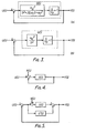
- Fig. l shows a tracking control system comprising two closed loops, that is, the first closed loop and the second closed loop.
- the first closed loop consists of a read head 1, plural detectors 3, the first control circuit 4, a driving amplifier 5, and an actuator.
- the second closed loop consists of said read head 1, amplitude detecting means, synchronous detecting means, the second control circuit, said driving amplifier, and said actuator.
- Said read head 1 reads information from an information carrier 10 which is rotated by a motor 11.
- Said actuator 2 operatively coupled to said read head 1 moves the whole of said read head 1 or a part of it. Accordingly, the reading position where information is read with said read head 1 is moved by said actuator 2.
- Plural detectors 3 detect tracking error, that is, a deviation of the reading position from the regular position relative to the information track being read.
- the differential output from said plural detectors 3 is amplified and processed by the first control circuit 4 which includes a differential amplifier and phase lead element.
- the output signal from said first control amplifier 4 is amplified by the driving amplifier 5 to drive the actuator 2. In this way the first closed loop is formed.
- the open loop transfer function G l (s) is generally discribed as follows: or where ⁇ o is the resonant angular frequency of the actuator, is the damping coefficient of said resonance, ⁇ p is the corner angular frequency of the phase lead element, and ⁇ N is a constant (» ⁇ o ) which is nearly equal to the cross-over angular frequency without said phase lead element.
- Equation (Eq., hereafter) (la) is the open loop transfer function when a damper suspends the moving element which is moved by said actuator
- Eq.(lb) is the open loop transfer function when said damper is not used.
- the typical characteristic of said actuator with a damper is shown in Fig. 2(A)
- the typical characteristic of said actuator without a damper is shown in Fig. 2(B). Both types of actuator are useful for the tracking control system.
- Figs. 3(A) and 3(B) show abstract block diagrams of the first closed loop corresponding to Eq.(la) and Eq.(lb), respectively.
- U(s) is a reference input (displacement of the information track) and Y(s) is a controlled variable (movement of the reading position on the information track).
- the steady-state position error e s to the reference input of step function u is Usually, the tracking control system is designed so that the steady-state position error e is reduced to be less than a permissible value.
- the ideal tracking control system mentioned above is difficult to accomplish with the aid of plural detectors to detect tracking error differentially, because the tracking error is detected indirectly. Therefore, the block diagram of the first closed loop is described as shown in Fig. 4.
- N(s) is a noise input caused by temperature drift, maladjustment of detectors, or a variation of some condition of the information carrier.
- Eq.(3) means that the controlled variable Y(s) includes the tracking error of N(s) in addition to the steady-state position error e s .
- This tracking error N(s) is inherent to differential tracking error detection.
- FIG. 5 is an abstract block diagram to explain the principle of the present invention.
- the tracking error E(s) becomes as follows:
- the noise N(s) produced by the differential error detecting process consists of low frequency component only
- the open loop transfer function G'(s) of the second closed loop is required to be great enough only in the low frequency region to suppress the noise N(sf.
- the second closed loop for parallel compensation must employ means for detecting tracking error without significant noise.
- the second closed loop (employing the wobbling method) is embodied in Fig. 1.
- the second closed loop functions are as follows.
- the oscillator 6 is oscillating at a properly selected frequency.
- the output signal from the oscillator 6 is fed into the first closed loop.
- the oscillator 6 feeds the output signal to the driving amplifier 5.
- the reading position is wobbled.
- the amplitude of the read out signal is varied by the wobbling.
- the amplitude detecting means 7 detects the amplitude of the read out signal to produce the signal proportional to said amplitude of the read out signal. Envelope demodulation or rectification can be applied to said amplitude detecting means 7.
- the synchronous detecting means 8 produces the tracking error signal from the output signal of the amplitude detecting means 7.
- a multiplying circuit can be applied to the synchronous detecting means 8.
- the second control circuit 9 amplifies and processes the tracking error signal detected by the wobbling method mentioned above. Then the output signal from said second control circuit is fed to the driving amplifier 5 to control reading position. In this way, the second closed loop performs.
- the second control circuit 9 includes an integral element and/or the first control circuit 4 includes a differential element so that the second closed loop is dominant-only in the low frequency region.
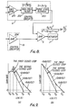
- Fig. 6 shows a block diagram of an example of the first and the second control circuits.
- the first control circuit consists of a differential amplifier 101 and a phase lead element 102.
- the second control circuit consists of an amplifier 103 and an integral element 104.
- the open loop transfer function G(s) of the first closed loop and the open loop transfer function G'(s) of the second closed loop are respectively described as follows: or and or Eqs.(5a) and (6a) and Eqs.(6a) and (6b) correspond to the characteristics of the actuator shown in Figs. 2(A) and 2(B), respectively.
- Open loop gains are shown in Figs.
- ⁇ d is the angular frequency which divides the frequency domain into two regions. In the lower frequency region, the second closed loop is dominant and in the higher frequency region, the first closed loop is dominant.
- the angular frequency ⁇ c is the cross-over frequency of the tracking control system.
- Fig. 8 shows a block diagram of another example of the first and the second control circuit.
- the first control circuit consists of a differential amplifier 201, a differential element 202, and a phase lead element 203.
- the second control circuit consists of an amplifier 204.
- the open loop transfer function G(s) of the first closed loop and the open loop transfer function G'(s) of the second closed loop are respectively described as follows: or and or Open loop gains are shown in Figs. 9(A) and 9(B) corresponding to Eqs.(7a), (7b), (8a) and (8b) as well as Figs. 7(A) and 7(B).
- the tracking control system can acomplish high speed and high precision control without using a special actuator.
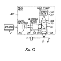
- An optical read head 301 comprises a light source 302, a focussing lens 305, a detecting optical system 306, and plural photo-detectors 309. Said light source 302 radiates a light beam 310.
- said light source 302 consists of a laser diode 303 and a collimating lens 304.
- a focussing lens focuses said light beam 310 to form a read spot 311 on the information carrier 10.
- Said light beam 310 is reflected by the information carrier 10 and collected by said focussing lens 305 to be formed reflected light beam 312.
- Said ref--lected light beam 312 is separated from the light beam 310 by a beam splitter 307 and processed by a processing optical block 308.
- a detecting optical system cousists of said focussing lens 305, said beam splitter 307, and said.processing optical block 308. Then said reflected light beam 312 is converted to a electrical signal by plural photo-detectors 309. The sum of the output signals from said photo-detectors 309 is the information signal and the difference of said output signals is tracking error signal.
- Said processing optical block 308, for example, consists of a positive lens for tracking error detection in the direction across the information track in the information plane, or consists of a positive lens and asymmetric element for tracking error detection in the direction normal to the information plane.
- the tracking error signal detected by the photo-detectors. 309 tend to includes much false signal, because of a temperature drift, a valiation of intensity of reflected light beam 312, or a warp of the information carrier.
- the optical read head 307 is wobbled by an actuator 2 to detect the accurate tracking error. Said actuator 2 moves the optical read head to control the global position of the read spot 311 in addition to the wobbling.
- the actuator for wobbling and tracking control may move the focussing lens 305 or other parts in the optical read head 301.
- Fig. 10 shows the optical read head for a reflective information carrier, but the fundamental constitution of the optical read head for a transparent information carrier is almost the same as the optical read head mentioned above.
Applications Claiming Priority (2)
| Application Number | Priority Date | Filing Date | Title |
|---|---|---|---|
| JP5271/81 | 1981-01-16 | ||
| JP56005271A JPS57120238A (en) | 1981-01-16 | 1981-01-16 | Reproducing device |
Publications (3)
| Publication Number | Publication Date |
|---|---|
| EP0056712A2 true EP0056712A2 (de) | 1982-07-28 |
| EP0056712A3 EP0056712A3 (en) | 1982-08-11 |
| EP0056712B1 EP0056712B1 (de) | 1984-09-19 |
Family
ID=11606562
Family Applications (1)
| Application Number | Title | Priority Date | Filing Date |
|---|---|---|---|
| EP82300203A Expired EP0056712B1 (de) | 1981-01-16 | 1982-01-15 | Informationsleseeinrichtung mit Nachführsystem |
Country Status (4)
| Country | Link |
|---|---|
| US (1) | US4488276A (de) |
| EP (1) | EP0056712B1 (de) |
| JP (1) | JPS57120238A (de) |
| DE (1) | DE3260743D1 (de) |
Cited By (7)
| Publication number | Priority date | Publication date | Assignee | Title |
|---|---|---|---|---|
| EP0139531A2 (de) * | 1983-10-20 | 1985-05-02 | Unisys Corporation | Spurnachlaufservosystem für Plattenvorrichtungen mit hoher Speicherdichte |
| EP0151220A1 (de) * | 1983-11-09 | 1985-08-14 | Sharp Kabushiki Kaisha | Servosystem zum Positionieren eines optischen Strahls |
| US4543621A (en) * | 1982-06-10 | 1985-09-24 | Datacopy Corporation | Spiral track disk drive |
| WO1986004178A1 (en) * | 1985-01-11 | 1986-07-17 | Deutsche Thomson-Brandt Gmbh | Reading device for the optical scanning of information recorded on a movable disc-shaped medium |
| EP0238138A2 (de) * | 1986-03-17 | 1987-09-23 | Koninklijke Philips Electronics N.V. | Mehrfaches Spurverfolgungssystem |
| EP0274567A2 (de) * | 1983-11-09 | 1988-07-20 | Sharp Kabushiki Kaisha | Servosystem zum Positionieren eines optischen Strahls |
| FR2652435A1 (fr) * | 1989-09-14 | 1991-03-29 | Mitsubishi Electric Corp | Appareil optique de lecture/ecriture presentant de tres bonnes performances de suivi de piste. |
Families Citing this family (6)
| Publication number | Priority date | Publication date | Assignee | Title |
|---|---|---|---|---|
| JPH0750415B2 (ja) * | 1984-10-08 | 1995-05-31 | オリンパス光学工業株式会社 | 光学式記録再生装置のサーボループ回路 |
| US4745588A (en) * | 1985-04-16 | 1988-05-17 | Olympus Optical Co., Ltd. | Tracking control apparatus |
| JP2681933B2 (ja) * | 1987-07-24 | 1997-11-26 | 松下電器産業株式会社 | 記録再生装置 |
| DE3732903A1 (de) * | 1987-09-30 | 1989-04-13 | Thomson Brandt Gmbh | Optische abtastvorrichtung |
| JP2911449B2 (ja) * | 1987-10-29 | 1999-06-23 | パイオニア株式会社 | 光学式情報読取装置 |
| JP3336778B2 (ja) * | 1994-11-25 | 2002-10-21 | 松下電器産業株式会社 | トラッキング誤差検出装置 |
Citations (7)
| Publication number | Priority date | Publication date | Assignee | Title |
|---|---|---|---|---|
| FR2135974A5 (de) * | 1971-04-01 | 1972-12-22 | Ibm | |
| DE2326662A1 (de) * | 1972-08-25 | 1974-03-21 | Information Storage Systems | Regelungsvorrichtung fuer ein servosystem |
| US3947881A (en) * | 1975-04-21 | 1976-03-30 | Control Data Corporation | Servo positioning error control for magnetic disk file |
| US3985952A (en) * | 1974-02-04 | 1976-10-12 | Zenith Radio Corporation | Elasto-optic device for spot wobble in a video disc player |
| DE2701538A1 (de) * | 1976-01-28 | 1977-08-04 | Philips Nv | Vorrichtung zum auslesen eines aufzeichnungstraegers, auf dem information, z.b. bild- und/oder toninformation angebracht ist |
| FR2346805A1 (fr) * | 1976-04-02 | 1977-10-28 | Sony Corp | Servomecanique pour appareils d'enregistrement et de lecture a support |
| US4180839A (en) * | 1977-04-05 | 1979-12-25 | Bell & Howell Company | Information reproducing apparatus |
Family Cites Families (4)
| Publication number | Priority date | Publication date | Assignee | Title |
|---|---|---|---|---|
| US3932700A (en) * | 1974-02-04 | 1976-01-13 | Zenith Radio Corporation | Focus tracking registration for optical reproducing systems |
| AR205839A1 (es) * | 1974-09-30 | 1976-06-07 | Mca Disco Vision | Servodisposicion para recorrer opticamente y leer simultaneamente un canal de informacion almacenado en un disco de video |
| JPS54102107A (en) * | 1978-01-30 | 1979-08-11 | Hitachi Ltd | Control information detecting method |
| JPS6048809B2 (ja) * | 1979-10-16 | 1985-10-29 | パイオニアビデオ株式会社 | 情報読取装置におけるトラッキングサ−ボ引込装置 |
-
1981
- 1981-01-16 JP JP56005271A patent/JPS57120238A/ja active Granted
-
1982
- 1982-01-15 EP EP82300203A patent/EP0056712B1/de not_active Expired
- 1982-01-15 DE DE8282300203T patent/DE3260743D1/de not_active Expired
- 1982-01-15 US US06/339,509 patent/US4488276A/en not_active Expired - Lifetime
Patent Citations (12)
| Publication number | Priority date | Publication date | Assignee | Title |
|---|---|---|---|---|
| FR2135974A5 (de) * | 1971-04-01 | 1972-12-22 | Ibm | |
| DE2326662A1 (de) * | 1972-08-25 | 1974-03-21 | Information Storage Systems | Regelungsvorrichtung fuer ein servosystem |
| FR2197195A1 (de) * | 1972-08-25 | 1974-03-22 | Information Storage Systems | |
| US3808486A (en) * | 1972-08-25 | 1974-04-30 | Information Storage Systems | Selective frequency compensation for a servo system |
| GB1433213A (en) * | 1972-08-25 | 1976-04-22 | Information Storage Systems | Servo systems |
| US3985952A (en) * | 1974-02-04 | 1976-10-12 | Zenith Radio Corporation | Elasto-optic device for spot wobble in a video disc player |
| US3947881A (en) * | 1975-04-21 | 1976-03-30 | Control Data Corporation | Servo positioning error control for magnetic disk file |
| DE2701538A1 (de) * | 1976-01-28 | 1977-08-04 | Philips Nv | Vorrichtung zum auslesen eines aufzeichnungstraegers, auf dem information, z.b. bild- und/oder toninformation angebracht ist |
| FR2339929A1 (fr) * | 1976-01-28 | 1977-08-26 | Philips Nv | Dispositif pour la lecture d'un porteur d'enregistrement dans lequel est enregistree de l'information, par exemple de l'information image et/ou son |
| GB1572409A (en) * | 1976-01-28 | 1980-07-30 | Philips Electronic Associated | Optical record player |
| FR2346805A1 (fr) * | 1976-04-02 | 1977-10-28 | Sony Corp | Servomecanique pour appareils d'enregistrement et de lecture a support |
| US4180839A (en) * | 1977-04-05 | 1979-12-25 | Bell & Howell Company | Information reproducing apparatus |
Non-Patent Citations (3)
| Title |
|---|
| I.B.M. Journal of Research and Development, Vol. 18, No. 6, November 1974 New York (US) OSWALD: "Design of a Disk File Head-Positioning Servo" pages 506-512 * |
| I.B.M. Technical Disclosure Bulletin, Vol.22, No. 11, April 1980, New York (US) Palmer: "Fast Eigenvector Control of a Disk File Actuator" pages 5069-5075 *figures 1-5; pages 5069-5075* * |
| Review of Electrical Communication Laboratories, Vol.28, No.5-6, May-June 1980, Tokyo (JP) KANEKO et al.: "Development of 800 Mega Byte Disk Drive" pages 368-378 * |
Cited By (10)
| Publication number | Priority date | Publication date | Assignee | Title |
|---|---|---|---|---|
| US4543621A (en) * | 1982-06-10 | 1985-09-24 | Datacopy Corporation | Spiral track disk drive |
| EP0139531A2 (de) * | 1983-10-20 | 1985-05-02 | Unisys Corporation | Spurnachlaufservosystem für Plattenvorrichtungen mit hoher Speicherdichte |
| EP0139531A3 (en) * | 1983-10-20 | 1987-04-22 | Memorex Corporation | Track following servo for higher density disk files |
| EP0151220A1 (de) * | 1983-11-09 | 1985-08-14 | Sharp Kabushiki Kaisha | Servosystem zum Positionieren eines optischen Strahls |
| EP0274567A2 (de) * | 1983-11-09 | 1988-07-20 | Sharp Kabushiki Kaisha | Servosystem zum Positionieren eines optischen Strahls |
| EP0274567A3 (en) * | 1983-11-09 | 1988-08-10 | Sharp Kabushiki Kaisha | Servo-system for the positioning of an optical head |
| WO1986004178A1 (en) * | 1985-01-11 | 1986-07-17 | Deutsche Thomson-Brandt Gmbh | Reading device for the optical scanning of information recorded on a movable disc-shaped medium |
| EP0238138A2 (de) * | 1986-03-17 | 1987-09-23 | Koninklijke Philips Electronics N.V. | Mehrfaches Spurverfolgungssystem |
| EP0238138A3 (en) * | 1986-03-17 | 1989-12-13 | Laser Magnetic Storage International Company | A multistage tracking system |
| FR2652435A1 (fr) * | 1989-09-14 | 1991-03-29 | Mitsubishi Electric Corp | Appareil optique de lecture/ecriture presentant de tres bonnes performances de suivi de piste. |
Also Published As
| Publication number | Publication date |
|---|---|
| EP0056712B1 (de) | 1984-09-19 |
| JPS6223372B2 (de) | 1987-05-22 |
| DE3260743D1 (en) | 1984-10-25 |
| EP0056712A3 (en) | 1982-08-11 |
| JPS57120238A (en) | 1982-07-27 |
| US4488276A (en) | 1984-12-11 |
Similar Documents
| Publication | Publication Date | Title |
|---|---|---|
| EP0056712B1 (de) | Informationsleseeinrichtung mit Nachführsystem | |
| EP0238162A2 (de) | Optisches Informationswiedergabegerät | |
| GB2110843A (en) | A tracking servo signal generating device in an apparatus for reading recorded information | |
| US4956833A (en) | Objective driving device for an optical disk apparatus | |
| CN1032276C (zh) | 光学扫描装置 | |
| NL8105347A (nl) | Inrichting voor het optisch aftasten van een schijfvormige registratiedrager. | |
| NL9200808A (nl) | Optische schrijf- en/of leesinrichting. | |
| US5970033A (en) | Tracking control unit for optical disk drive capable of suppressing control residual derived from disturbance | |
| CA1160874A (en) | Optical focusing device | |
| EP0327090A3 (de) | Optisches Aufnahme/Wiedergabegerät | |
| EP0145787B1 (de) | Anordnung zur spurnachlaufregelung auf einer aufgezeichneten platte eines wiedergabegerätes | |
| US4627040A (en) | Optical disk tracking apparatus | |
| JPH0793764A (ja) | 対物レンズ位置制御方法及び装置 | |
| JPH0612573B2 (ja) | 情報読取装置における記録トラックとピックアップとのトラック直交方向相対位置制御装置 | |
| JPS6120054B2 (de) | ||
| KR20010074984A (ko) | 정보매체를 주사하는 장치 및 방법 | |
| JPH06131680A (ja) | 光ヘッド装置及びトラッキングエラー検出方法 | |
| EP0285723A2 (de) | Weglängeneinstellung für Laserwinkelgeschwindigkeitsmesser | |
| JPH031751B2 (de) | ||
| JPS5928255A (ja) | 光学式情報再生装置 | |
| JP2785706B2 (ja) | 光ピックアップ装置 | |
| JPH04129035A (ja) | 光学的情報記録/再生装置 | |
| JPS59217237A (ja) | 焦点制御装置 | |
| JP2564452B2 (ja) | 補償光学制御装置 | |
| EP0246919B1 (de) | Servoeinrichtung zum Spurfolgen für ein Datenwiedergabegerät |
Legal Events
| Date | Code | Title | Description |
|---|---|---|---|
| PUAI | Public reference made under article 153(3) epc to a published international application that has entered the european phase |
Free format text: ORIGINAL CODE: 0009012 |
|
| PUAL | Search report despatched |
Free format text: ORIGINAL CODE: 0009013 |
|
| AK | Designated contracting states |
Designated state(s): DE FR GB |
|
| AK | Designated contracting states |
Designated state(s): DE FR GB |
|
| 17P | Request for examination filed |
Effective date: 19830207 |
|
| GRAA | (expected) grant |
Free format text: ORIGINAL CODE: 0009210 |
|
| AK | Designated contracting states |
Designated state(s): DE FR GB |
|
| REF | Corresponds to: |
Ref document number: 3260743 Country of ref document: DE Date of ref document: 19841025 |
|
| ET | Fr: translation filed | ||
| PLBE | No opposition filed within time limit |
Free format text: ORIGINAL CODE: 0009261 |
|
| STAA | Information on the status of an ep patent application or granted ep patent |
Free format text: STATUS: NO OPPOSITION FILED WITHIN TIME LIMIT |
|
| 26N | No opposition filed | ||
| PGFP | Annual fee paid to national office [announced via postgrant information from national office to epo] |
Ref country code: GB Payment date: 19950105 Year of fee payment: 14 |
|
| PG25 | Lapsed in a contracting state [announced via postgrant information from national office to epo] |
Ref country code: GB Effective date: 19960115 |
|
| GBPC | Gb: european patent ceased through non-payment of renewal fee |
Effective date: 19960115 |
|
| PGFP | Annual fee paid to national office [announced via postgrant information from national office to epo] |
Ref country code: FR Payment date: 19970109 Year of fee payment: 16 |
|
| PGFP | Annual fee paid to national office [announced via postgrant information from national office to epo] |
Ref country code: DE Payment date: 19970124 Year of fee payment: 16 |
|
| PG25 | Lapsed in a contracting state [announced via postgrant information from national office to epo] |
Ref country code: FR Free format text: THE PATENT HAS BEEN ANNULLED BY A DECISION OF A NATIONAL AUTHORITY Effective date: 19980131 |
|
| PG25 | Lapsed in a contracting state [announced via postgrant information from national office to epo] |
Ref country code: DE Free format text: LAPSE BECAUSE OF NON-PAYMENT OF DUE FEES Effective date: 19981001 |
|
| REG | Reference to a national code |
Ref country code: FR Ref legal event code: ST |