EP0056669B1 - Turbine mit regelbarem Einlassquerschnitt - Google Patents
Turbine mit regelbarem Einlassquerschnitt Download PDFInfo
- Publication number
- EP0056669B1 EP0056669B1 EP82200035A EP82200035A EP0056669B1 EP 0056669 B1 EP0056669 B1 EP 0056669B1 EP 82200035 A EP82200035 A EP 82200035A EP 82200035 A EP82200035 A EP 82200035A EP 0056669 B1 EP0056669 B1 EP 0056669B1
- Authority
- EP
- European Patent Office
- Prior art keywords
- guide
- turbo
- blade
- expansion apparatus
- inlet sector
- Prior art date
- Legal status (The legal status is an assumption and is not a legal conclusion. Google has not performed a legal analysis and makes no representation as to the accuracy of the status listed.)
- Expired
Links
- 239000012530 fluid Substances 0.000 claims abstract description 25
- 230000000750 progressive effect Effects 0.000 claims description 9
- 230000007935 neutral effect Effects 0.000 claims description 3
- 230000000694 effects Effects 0.000 claims 2
- 230000001154 acute effect Effects 0.000 claims 1
- 238000002347 injection Methods 0.000 description 24
- 239000007924 injection Substances 0.000 description 24
- 239000007789 gas Substances 0.000 description 4
- 238000011084 recovery Methods 0.000 description 4
- 238000009434 installation Methods 0.000 description 3
- 238000000034 method Methods 0.000 description 2
- 238000011144 upstream manufacturing Methods 0.000 description 2
- 239000003638 chemical reducing agent Substances 0.000 description 1
- 230000036461 convulsion Effects 0.000 description 1
- 238000002513 implantation Methods 0.000 description 1
- 230000000977 initiatory effect Effects 0.000 description 1
- 230000003071 parasitic effect Effects 0.000 description 1
- XLYOFNOQVPJJNP-UHFFFAOYSA-N water Chemical compound O XLYOFNOQVPJJNP-UHFFFAOYSA-N 0.000 description 1
Images

Classifications
-
- F—MECHANICAL ENGINEERING; LIGHTING; HEATING; WEAPONS; BLASTING
- F01—MACHINES OR ENGINES IN GENERAL; ENGINE PLANTS IN GENERAL; STEAM ENGINES
- F01D—NON-POSITIVE DISPLACEMENT MACHINES OR ENGINES, e.g. STEAM TURBINES
- F01D17/00—Regulating or controlling by varying flow
- F01D17/10—Final actuators
- F01D17/12—Final actuators arranged in stator parts
- F01D17/14—Final actuators arranged in stator parts varying effective cross-sectional area of nozzles or guide conduits
- F01D17/16—Final actuators arranged in stator parts varying effective cross-sectional area of nozzles or guide conduits by means of nozzle vanes
- F01D17/165—Final actuators arranged in stator parts varying effective cross-sectional area of nozzles or guide conduits by means of nozzle vanes for radial flow, i.e. the vanes turning around axes which are essentially parallel to the rotor centre line
Definitions
- centripetal wheel of the turbine is done by a constant opening injection sector whose fixed guide vanes impose on the fluid a suitable orientation.
- US Pat. No. 3,799,689 shows a device for which the degree of opening of the blades is actuated by a servo motor itself controlled by an electrical system which it is always difficult to insert into a hydraulic turbine.
- the patent FR 918317 claims a turbofan comprising a turbine, actuated by the exhaust gases, the intake nozzles of which are closed to varying degrees by a movable screen, carrying a toothing which cooperates with a pinion actuated by a rack displaced by a piston, sliding inside a cylinder, and subjected to variable oil pressures depending on the speed.
- These various gears are difficult to transpose into a hydraulic application without taking serious risks of damage.
- the invention claimed below makes it possible to maintain the yield at its optimum value whatever the flow rate of the fluid and its application covers both the recovery of energy by expansion of gas at high pressure and that by expansion of water vapor. . In addition, it simplifies installation upstream of the machine by replacing the flow control valve, which is high cost and generates energy loss, with a simple shut-off valve.
- the invention essentially consists of a device making it possible to vary the sector of injection of the fluid without appreciably modifying the speed of the latter even if the flow rate undergoes significant fluctuations.
- This device comprises a regulator provided with a variable injection sector, the opening of which is adjusted according to the characteristics of the fluid conveyed.
- adjustable guide vanes controlled by a servo-motor whose action is proportional to the flow rate observed, are oriented so to obtain an adequate passage section.
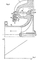
- FIG. 1 represents an injection sector consisting of fixed guide vanes, ensuring a minimum flow rate, and orientable guide vanes to adapt the passage section to variations in flow rate.
- a high-pressure body 1 conveys the fluid to introduce it radially by an injection sector 2 extending, in this example, over an arc of approximately 140 °.
- This injection sector 2 comprises, in the central zone, three fixed guide vanes 3, a first group of four guide vanes 4A, 5A, 6A, 7A each orientable by rotation around a pivot 4P, 5P, 6P, 7P and each controlled by an arm 4B, 5B, 6B, 7B secured at dawn and terminated by a roller 4R, 5R, 6R, 7R.
- These rollers are guided by a groove 8 formed in a control ring 9 concentric with a discharge cylinder 10 whose axis coincides with that of the machine.
- This injection sector 2 also includes a second group with three guide vanes 11 A, 12A, 13A each adjustable by rotation about a pivot 11 P, 12P, 13P, each controlled by an arm 11 B, 12B, 13B secured to dawn and ended with a roller 11R, 12R, 13R.
- These rollers 11 R, 12R, 13R are guided respectively by the grooves 14, 15, 16 of the control ring 9 which, by means of a linkage 17, is actuated by a servo motor not shown.
- FIG. 1 represents the injection sector 2 in the position corresponding to the minimum flow rate of the fluid. The latter is expanded by passing through the three channels formed by the three fixed guide vanes 3 and the orientable guide vane 11A.
- the control crown 9 rotates, clockwise, by an angle proportional to the increase in flow and the orientable guide vanes open successively and gradually according to the position of the rollers on the ramps of guide grooves. From the position shown in Figure 1, the steerable guide vane 4A gradually pivots according to the progression of the roller 4R on the ramp 8R of the groove 8 formed in the control crown 9. However, in order to establish a linear law between the angle of rotation of the control crown 9 and the passage section offered to the fluid, the orientable guide vane 11A begins its rotation before the total opening of the orientable guide vane 4A.
- the opening control of the adjustable guide vanes 4A, 5A, 6A is carried out by the single ramp 8R of the groove 8 while the opening control of the vanes 11A, 12A, 13A is made by the ramps 14R, 15R, 16R belonging respectively to the grooves 14, 15, 16 formed in the control ring 9.
- This control ring consists of two co-axial plates 18, 19 of the same diameter, made integral with one another and carrying one 18 the guide grooves 8 and 15 and the other 39 the guide grooves 14 and 16.
- the device described therefore makes it possible to adapt at any time a suitable opening of the injection sector 2 in order to keep the fluid conveyed at the same speed despite the numerous fluctuations in the flow rate. It thus allows optimum performance to be maintained at the installation whatever the fluid supply conditions.
- the device represented by FIGS. 1 and 2 is given by way of example of embodiment.
- the same invention also applies to an injection sector in which the number of fixed guide vanes is different or even zero. In the latter case, a regulator can then be obtained which can adapt to very low flow.
- the injection sector can extend over an arc different from that shown in FIG. 1. It is even possible to obtain an injection of the fluid over an opening of the order of 360 °. It is also possible that the order of opening of the orientable guide vanes takes place according to another process. For example, contrary to FIG. 1 where the progressive opening of the injection sector is done by extension of a central zone widening on either side of a minimum opening, an opening can be made. progressive spreading on one side of the minimum opening.
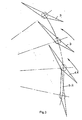
- FIG. 3 represents the orientable guide vane 4A in the fully open position while the orientable guide vane 5A is still completely closed.
- all the blades have an aerodynamic profile in the shape of a very flat triangle.
- the base of this triangle determines with its long side an edge which is the trailing edge of the blade and with its short side another edge which constitutes the leading edge of the blade.
- the apex of the triangle is rounded according to a curvature concentric with the pivot of the blade so as to determine a range on which the trailing edge of the neighboring blade can bear. This range, called neutral zone, allows the neighboring blade to keep the same position whatever the orientation of the blade on which it rests.
- the orientable guide vane 5A rests by its trailing edge on the neutral zone of the orientable guide vane 4A. Therefore the orientation of the steerable guide vane 4A can vary without changing the orientation of the steerable guide vane 5A.
- This configuration makes it possible not to create parasitic openings, generating eddies which modify the flow of the fluid and reduce the efficiency of the fluid expansion.
- FIG. 3 also shows an implantation of the pivots of the orientable guide vanes on the high-pressure body 1 so as to form converging channels, whatever the degree of opening of the vanes, to allow suitable relaxation of the fluids conveyed.
- the steerable guide vanes shown in Figure 3 have two wings which, counted from the axis of the pivot of the blade, are of unequal sizes. This asymmetry allows by the play of the pressures applied to the different faces of the triangle to obtain a resulting torque always acting in the same direction and to allow on the one hand to the whole linkage to work without jerk and on the other hand to roller, located at the end of the arm, to remain applied to the same flank of the groove formed in the control ring 9.
- the result of the forces acting on the different faces of the steerable guide vane 6A results in a torque acting in the opposite direction to the needles of a watch to apply the roller 6R to the lower flank of the groove 8.
- the regulator with variable injection sector equips the high-pressure body with a centripetal turbine. It is obvious that the same device can equip both the high and low pressure bodies of this turbine.
- control ring 9 consists of two independent co-axial plates actuated independently or simultaneously, according to the sequence, by a linkage to achieve a progressive opening or closing of the injection sector (2 ).
- This latter arrangement makes it possible in particular to produce an opening from 0 ° to 360 ° with a reduced rotation of the control ring 9.
Landscapes
- Engineering & Computer Science (AREA)
- Mechanical Engineering (AREA)
- General Engineering & Computer Science (AREA)
- Control Of Turbines (AREA)
- Structures Of Non-Positive Displacement Pumps (AREA)
- Superconductors And Manufacturing Methods Therefor (AREA)
- Turbine Rotor Nozzle Sealing (AREA)
- Supercharger (AREA)
Claims (9)
- Turboentspanner aus mindestens einer Zentripetalturbine, die auf der Welle der angetriebenen Maschine fliegend montiert ist, einer Rohrleitung, die das unter hohem Druck stehende Fluid zuführt und in einem Spiraldiffusor endet, einem Einlaßsektor (2), der das Fluid zu den Schaufeln der Zentripetalturbine hinleitet, einer Rohrleitung zur Abführung des entspannten Fluids, die Entlastungszylinder (10) genannt wird, einem Steuerkranz (9), der konzentrisch zu dem Entlastungszylinder (10) ist und die Leitschaufeln (4A, 5A, 6A, 7A, 11A, 12A, 13A) betätigt, um sie entsprechend einem bestimmten Winkel zu neigen, .
dadurch gekennzeichnet, daß der Turboentspanner einen Einlaßsektor (2) aufweist, der ganz oder teilweise aus Leitschaufeln (4A, 5A, 6A, 7A, 11A, 12A, 13A) besteht, die durch Führungsrampen (8, 14, 15, 16) ausgerichtet werden, die mit den Leitschaufeln (4A, 5A, 6A,7A, 11 A, 12A, 13A) so zusammenwirken, daß die Bewegung einer Schaufel beginnt, bevor die zuvor bewegte Schaufel vollständig angehalten wurde, damit die Öffnung oder die Schließung des Einlaßsektors (2) unter Einhaltung eines linearen Gesetzes zwischen dem Drehwinkel des Steuerkranzes (9) und dem Durchlaßquerschnitt des Einlaßsektors (2) erfolgt: - 2. Turboentspanner gemäß Anspruch 1, dadurch gekennzeichnet, daß seine Leitschauf ein ein aerodynamisches Profil aufweisen, das die allgemeine Form eines stark abgeflachten Dreiecks hat, dessen an die Grundlinie angrenzende spitze Winkel die Vorderkante beziehungsweise die Leckkante bilden, und dessen an der Spitze des Dreiecks gelegener stumpfer Winkel entsprechend einer Krümmung verrundet ist, die konzentrisch zu der in dem dicksten Bereich der Schaufel gelegenen Drehachse ist.
- 3. Turboentspanner gemäß einem der vorhergehenden Ansprüche, dadurch gekennzeichnet, daß die verstellbaren Leitschaufeln ab der Drehachse der Schaufel zwei Flügel von ungleicher Länge aufweisen.
- 4. Turboentspanner gemäß einem der vorhergehenden Ansprüche, dadurch gekennzeichnet, daß der größere Flügel der verstellbaren Leitschaufel am Ende eine Leckkante aufweist, und daß der kleinere Flügel der verstellbaren Leitschaufel am Ende eine Vorderkante aufweist.
- 5. Turboentspanner gemäß einem der vorhergehenden Ansprüche, dadurch gekennzeichnet, daß die Drehachsen der verstellbaren Leitschaufeln eine solche. geometrische Anordnung aufweisen, daß einerseits die Leckkante einer verstellbaren Leitschaufel (4A oder 5A) in der vollständig geschlossenen Position auf dem verundeten Teil des Winkels an der Spitze, der sogenannten neutralen Zone, der benachbarten festen oder beweglichen Schaufel (3 oder4A) aufliegt, und daß andererseits die Grundlinie des dreieckförmigen Profils einer verstellbaren Leitschaufel (4A oder 5A) in Verbindung mit der kleinen Seite des dreieckförmigen Profils der benachbarten, festen oder beweglichen Schaufel (3 oder 5A), unabhängig von dem Öffnungsgrad der einen oder der anderen der betrachteten Schaufeln, einen konvergenten Fluidverteilungskanal bildet:
- 6. Turboentspanner gemäß einem der vorhergehenden Ansprüche, dadurch gekennzeichnet, daß mindestens ein Steuerkranz (9), der konzentrisch zu dem Einlaßzylinder (10) ist und über ein Gestänge (17) betätigt wird, mit Führungsrampen (8,14,15,16) versehen ist, um mit Rollen (4R, 5R, 6R, 7R, 11R, 12R, 13R) zusammenzuwirken, von denen jede am Ende eines Arms (4B, 5B, 6B, 7B, 11B, 12B, 13B) montiert ist, der mit der Drehachse (4P, 5P, 6P, 7P, 11 P, 12P, 13P) jeder verstellbaren Leitschaufel (4A, 5A, 6A, 7A, 11A, 12A, 13A) fest verbunden ist, um eine progressive Öffnung oder Schließung des Einlaßsektors (2) zu verwirklichen.
- 7. Turboentspanner gemäß einem der vorhergehenden Ansprüche, dadurch gekennzeichnet, daß der Steuerkranz (9) aus zwei Platten (18 und 19) besteht, die miteinander fest verbunden sind, und von denen jede Führungsrampen (8,14,15, 16) aufweist, die so verteilt sind, daß eine progressive Öffnung oder Schließung des Einlaßsektors (2) verwirklicht wird.
- 8. Turboentspanner gemäß einem der vorhergehenden Ansprüche, dadurch gekennzeichnet, daß der Steuerkranz (9) von unabhängigen Platten gebildet wird, von denen jede Führungsrampen (8, 14,15,16) aufweist, die so verteilt sind, daß eine progressive Öffnung oder Schließung des Einlaßsektors (2) verwirklicht wird.
- 9. Turboentspanner gemäß einem der vorhergehenden Ansprüche, dadurch gekennzeichnet, daß ein durch das beförderte Fluid betätigter Servomotor mit dem Gestänge 17) des Steuerkranzes (9) verbunden ist, um die Offnung oder die Schließung des Einlaßsektors (2) zu bewirken.
Priority Applications (1)
| Application Number | Priority Date | Filing Date | Title |
|---|---|---|---|
| AT82200035T ATE23905T1 (de) | 1981-01-21 | 1982-01-14 | Turbine mit regelbarem einlassquerschnitt. |
Applications Claiming Priority (2)
| Application Number | Priority Date | Filing Date | Title |
|---|---|---|---|
| EP81870007 | 1981-01-21 | ||
| EP81870007A EP0056569A1 (de) | 1981-01-21 | 1981-01-21 | Turbine mit regelbarem Einlassquerschnitt |
Publications (2)
| Publication Number | Publication Date |
|---|---|
| EP0056669A1 EP0056669A1 (de) | 1982-07-28 |
| EP0056669B1 true EP0056669B1 (de) | 1986-11-26 |
Family
ID=8188745
Family Applications (2)
| Application Number | Title | Priority Date | Filing Date |
|---|---|---|---|
| EP81870007A Withdrawn EP0056569A1 (de) | 1981-01-21 | 1981-01-21 | Turbine mit regelbarem Einlassquerschnitt |
| EP82200035A Expired EP0056669B1 (de) | 1981-01-21 | 1982-01-14 | Turbine mit regelbarem Einlassquerschnitt |
Family Applications Before (1)
| Application Number | Title | Priority Date | Filing Date |
|---|---|---|---|
| EP81870007A Withdrawn EP0056569A1 (de) | 1981-01-21 | 1981-01-21 | Turbine mit regelbarem Einlassquerschnitt |
Country Status (3)
| Country | Link |
|---|---|
| EP (2) | EP0056569A1 (de) |
| AT (1) | ATE23905T1 (de) |
| DE (1) | DE3274480D1 (de) |
Families Citing this family (6)
| Publication number | Priority date | Publication date | Assignee | Title |
|---|---|---|---|---|
| JPH01227823A (ja) * | 1988-03-08 | 1989-09-12 | Honda Motor Co Ltd | タービンの可変ノズル構造 |
| DE19741992A1 (de) * | 1997-09-24 | 1999-03-25 | Voith Hydro Gmbh & Co Kg | Strömungsmaschine, insbesondere Wasserturbine |
| DE19936507A1 (de) * | 1999-08-05 | 2001-02-15 | 3K Warner Turbosystems Gmbh | Turbinenleitschaufel für einen Abgas-Turbolader |
| AT411615B (de) * | 2000-10-31 | 2004-03-25 | Blank Otto Ing | Abgasturbolader für eine brennkraftmaschine |
| DE102008004014A1 (de) * | 2008-01-11 | 2009-07-23 | Continental Automotive Gmbh | Leitschaufel für eine variable Turbinengeometrie |
| DE102009057987B4 (de) | 2009-12-11 | 2020-08-20 | BMTS Technology GmbH & Co. KG | Ladeeinrichtung und Leitschaufel für eine derartige Ladeeinrichtung |
Family Cites Families (12)
| Publication number | Priority date | Publication date | Assignee | Title |
|---|---|---|---|---|
| CH254459A (de) * | 1945-03-02 | 1948-04-30 | Berger Hans | Abgasturbolader. |
| FR918317A (fr) * | 1945-08-10 | 1947-02-05 | Brandt Edgar Ets | Turbo-soufflante à gaz d'échappement alimentant un moteur à combustion interne à grande variation de vitesse |
| GB704351A (en) * | 1951-03-21 | 1954-02-17 | Alan Muntz & Co Ltd | Improvements in and relating to turbines operated by gases supplied by free-piston gas-generators |
| GB731822A (en) * | 1952-03-14 | 1955-06-15 | Power Jets Res & Dev Ltd | Improvements relating to turbines or compressors for operation with gaseous fluids |
| US2985427A (en) * | 1955-11-25 | 1961-05-23 | Gen Electric | Adjustable blading for fluid flow machines |
| US3029067A (en) * | 1956-05-31 | 1962-04-10 | Garrett Corp | Variable area nozzle means for turbines |
| US3243159A (en) * | 1964-04-27 | 1966-03-29 | Ingersoll Rand Co | Guide vane mechanism for centrifugal fluid-flow machines |
| GB1268796A (en) * | 1969-09-22 | 1972-03-29 | Garrett Corp | Sealing adjustable stator vanes in rotary fluid flow machines |
| US3799689A (en) * | 1971-05-14 | 1974-03-26 | Hitachi Ltd | Operating apparatus for guide vanes of hydraulic machine |
| GB1400718A (en) * | 1971-12-11 | 1975-07-23 | Lucas Industries Ltd | Control vane arrangement for a turbine |
| US4179247A (en) * | 1977-01-14 | 1979-12-18 | Wrr Industries, Inc. | Turbocharger having variable area turbine nozzles |
| BE871024A (fr) * | 1978-10-05 | 1979-04-05 | Acec | Ensemble turbine de detente - generatrice de courant. |
-
1981
- 1981-01-21 EP EP81870007A patent/EP0056569A1/de not_active Withdrawn
-
1982
- 1982-01-14 AT AT82200035T patent/ATE23905T1/de not_active IP Right Cessation
- 1982-01-14 DE DE8282200035T patent/DE3274480D1/de not_active Expired
- 1982-01-14 EP EP82200035A patent/EP0056669B1/de not_active Expired
Also Published As
| Publication number | Publication date |
|---|---|
| ATE23905T1 (de) | 1986-12-15 |
| EP0056569A1 (de) | 1982-07-28 |
| EP0056669A1 (de) | 1982-07-28 |
| DE3274480D1 (en) | 1987-01-15 |
Similar Documents
| Publication | Publication Date | Title |
|---|---|---|
| EP2288813B1 (de) | Einspritzung von luft in den fliessweg eines turbomaschinenkompressors | |
| FR2814205A1 (fr) | Turbomachine a veine d'ecoulement ameliore | |
| FR2688543A1 (fr) | Appareil reglable de guidage de l'ecoulement pour une turbine de turbocompresseur a gaz d'echappement. | |
| CA2639181C (fr) | Aube a calage variable de turbomachine | |
| EP3247885B1 (de) | System zur steuerung von schaufeln mit variablem neigungswinkel für einen turbinenmotor | |
| EP0056669B1 (de) | Turbine mit regelbarem Einlassquerschnitt | |
| EP1500824B1 (de) | Hochdruckverdichter für Hybridkreislauf und Turbomaschine mit einem solchen Verdichter | |
| CA2932998C (fr) | Compresseur de turbomachine, en particulier de turbopropulseur ou de turboreacteur d'avion | |
| FR3072719A1 (fr) | Anneau de commande d'un etage d'aubes a calage variable pour une turbomachine | |
| EP0698739A1 (de) | Abblassvorrichtung für Turbomaschine | |
| CA2812691C (fr) | Dispositif hydraulique d'un dispositif de commande tel qu'un dispositif de changement de pas d'helice | |
| EP2864594B1 (de) | Bläser mit variabler einstellung der schaufeln mittels differentieller rotation der rotorscheiben des bläsers | |
| BE501076A (de) | ||
| EP0179078B1 (de) | Hydraulische Turbine mit teilweise trockenlaufendem Laufrad und Injektor | |
| EP0043305A1 (de) | Turbine mit regelbarem Spiralgehäuse für die Gaszufuhr | |
| FR3072430B1 (fr) | Anneau de commande d'un etage d'aubes a calage variable pour une turbomachine | |
| EP0240381A1 (de) | Regelungseinrichtung für die Zufuhr einer Radialturbine und Turbine mit einer solchen Einrichtung | |
| FR3093136A1 (fr) | Carter d’entree pour une turbomachine d’aeronef | |
| WO2022263753A1 (fr) | Systeme de changement de pas des pales d'une helice d'une turbomachine | |
| FR2485102A1 (fr) | Organe de distribution pour machine hydroelectrique de haute chute | |
| FR2545153A1 (fr) | Turbine centripete perfectionnee | |
| FR3140904A1 (fr) | Systeme de changement de pas avec chaine d’entrainement et turbomachine equipee d’un tel systeme de changement de pas | |
| FR2469575A1 (fr) | Turbine multietagee de turboforeuse | |
| FR2998011A1 (fr) | Compresseur de turbomachine a deux flux separes | |
| BE466780A (de) |
Legal Events
| Date | Code | Title | Description |
|---|---|---|---|
| PUAI | Public reference made under article 153(3) epc to a published international application that has entered the european phase |
Free format text: ORIGINAL CODE: 0009012 |
|
| AK | Designated contracting states |
Designated state(s): AT BE CH DE FR GB IT LI LU NL SE |
|
| 17P | Request for examination filed |
Effective date: 19830307 |
|
| RAP1 | Party data changed (applicant data changed or rights of an application transferred) |
Owner name: ATELIERS DE CONSTRUCTIONS ELECTRIQUES DE CHARLEROI |
|
| GRAA | (expected) grant |
Free format text: ORIGINAL CODE: 0009210 |
|
| AK | Designated contracting states |
Kind code of ref document: B1 Designated state(s): AT BE CH DE FR GB IT LI LU NL SE |
|
| REF | Corresponds to: |
Ref document number: 23905 Country of ref document: AT Date of ref document: 19861215 Kind code of ref document: T |
|
| PG25 | Lapsed in a contracting state [announced via postgrant information from national office to epo] |
Ref country code: SE Effective date: 19861130 |
|
| BECN | Be: change of holder's name |
Effective date: 19861126 |
|
| REF | Corresponds to: |
Ref document number: 3274480 Country of ref document: DE Date of ref document: 19870115 |
|
| PG25 | Lapsed in a contracting state [announced via postgrant information from national office to epo] |
Ref country code: LU Free format text: LAPSE BECAUSE OF NON-PAYMENT OF DUE FEES Effective date: 19870131 |
|
| ITF | It: translation for a ep patent filed | ||
| PLBE | No opposition filed within time limit |
Free format text: ORIGINAL CODE: 0009261 |
|
| STAA | Information on the status of an ep patent application or granted ep patent |
Free format text: STATUS: NO OPPOSITION FILED WITHIN TIME LIMIT |
|
| 26N | No opposition filed | ||
| REG | Reference to a national code |
Ref country code: CH Ref legal event code: PFA Free format text: ACEC |
|
| PGFP | Annual fee paid to national office [announced via postgrant information from national office to epo] |
Ref country code: NL Payment date: 19890131 Year of fee payment: 11 |
|
| PGFP | Annual fee paid to national office [announced via postgrant information from national office to epo] |
Ref country code: CH Payment date: 19900126 Year of fee payment: 9 |
|
| PGFP | Annual fee paid to national office [announced via postgrant information from national office to epo] |
Ref country code: LU Payment date: 19900130 Year of fee payment: 9 |
|
| ITTA | It: last paid annual fee | ||
| PGFP | Annual fee paid to national office [announced via postgrant information from national office to epo] |
Ref country code: AT Payment date: 19900131 Year of fee payment: 9 Ref country code: GB Payment date: 19900131 Year of fee payment: 9 |
|
| PGFP | Annual fee paid to national office [announced via postgrant information from national office to epo] |
Ref country code: DE Payment date: 19900326 Year of fee payment: 9 |
|
| PG25 | Lapsed in a contracting state [announced via postgrant information from national office to epo] |
Ref country code: AT Effective date: 19910114 Ref country code: GB Effective date: 19910114 |
|
| PGFP | Annual fee paid to national office [announced via postgrant information from national office to epo] |
Ref country code: FR Payment date: 19910125 Year of fee payment: 10 |
|
| PG25 | Lapsed in a contracting state [announced via postgrant information from national office to epo] |
Ref country code: LI Effective date: 19910131 Ref country code: CH Effective date: 19910131 |
|
| GBPC | Gb: european patent ceased through non-payment of renewal fee | ||
| REG | Reference to a national code |
Ref country code: CH Ref legal event code: PL |
|
| PG25 | Lapsed in a contracting state [announced via postgrant information from national office to epo] |
Ref country code: DE Effective date: 19911001 |
|
| PG25 | Lapsed in a contracting state [announced via postgrant information from national office to epo] |
Ref country code: NL Effective date: 19920801 |
|
| NLV4 | Nl: lapsed or anulled due to non-payment of the annual fee | ||
| PG25 | Lapsed in a contracting state [announced via postgrant information from national office to epo] |
Ref country code: FR Effective date: 19920930 |
|
| REG | Reference to a national code |
Ref country code: FR Ref legal event code: ST |
|
| PGFP | Annual fee paid to national office [announced via postgrant information from national office to epo] |
Ref country code: BE Payment date: 19930127 Year of fee payment: 12 |
|
| PG25 | Lapsed in a contracting state [announced via postgrant information from national office to epo] |
Ref country code: BE Effective date: 19940131 |
|
| BERE | Be: lapsed |
Owner name: S.A. ACEC Effective date: 19940131 |