EP0056569A1 - Turbine mit regelbarem Einlassquerschnitt - Google Patents
Turbine mit regelbarem Einlassquerschnitt Download PDFInfo
- Publication number
- EP0056569A1 EP0056569A1 EP81870007A EP81870007A EP0056569A1 EP 0056569 A1 EP0056569 A1 EP 0056569A1 EP 81870007 A EP81870007 A EP 81870007A EP 81870007 A EP81870007 A EP 81870007A EP 0056569 A1 EP0056569 A1 EP 0056569A1
- Authority
- EP
- European Patent Office
- Prior art keywords
- turbo
- fluid
- injection
- regulator according
- opening
- Prior art date
- Legal status (The legal status is an assumption and is not a legal conclusion. Google has not performed a legal analysis and makes no representation as to the accuracy of the status listed.)
- Withdrawn
Links
- 239000012530 fluid Substances 0.000 claims abstract description 24
- 230000000750 progressive effect Effects 0.000 claims abstract description 8
- 238000002347 injection Methods 0.000 claims description 28
- 239000007924 injection Substances 0.000 claims description 28
- 230000007935 neutral effect Effects 0.000 claims description 3
- 230000001154 acute effect Effects 0.000 claims 1
- 238000007599 discharging Methods 0.000 claims 1
- 239000007789 gas Substances 0.000 abstract description 4
- 238000011084 recovery Methods 0.000 description 4
- 238000009434 installation Methods 0.000 description 3
- 238000000034 method Methods 0.000 description 2
- 238000011144 upstream manufacturing Methods 0.000 description 2
- 239000003638 chemical reducing agent Substances 0.000 description 1
- 238000002513 implantation Methods 0.000 description 1
- 230000000977 initiatory effect Effects 0.000 description 1
- 230000003071 parasitic effect Effects 0.000 description 1
- XLYOFNOQVPJJNP-UHFFFAOYSA-N water Chemical compound O XLYOFNOQVPJJNP-UHFFFAOYSA-N 0.000 description 1
Images


Classifications
-
- F—MECHANICAL ENGINEERING; LIGHTING; HEATING; WEAPONS; BLASTING
- F01—MACHINES OR ENGINES IN GENERAL; ENGINE PLANTS IN GENERAL; STEAM ENGINES
- F01D—NON-POSITIVE DISPLACEMENT MACHINES OR ENGINES, e.g. STEAM TURBINES
- F01D17/00—Regulating or controlling by varying flow
- F01D17/10—Final actuators
- F01D17/12—Final actuators arranged in stator parts
- F01D17/14—Final actuators arranged in stator parts varying effective cross-sectional area of nozzles or guide conduits
- F01D17/16—Final actuators arranged in stator parts varying effective cross-sectional area of nozzles or guide conduits by means of nozzle vanes
- F01D17/165—Final actuators arranged in stator parts varying effective cross-sectional area of nozzles or guide conduits by means of nozzle vanes for radial flow, i.e. the vanes turning around axes which are essentially parallel to the rotor centre line
Definitions
- centripetal wheel of the turbine is done by a constant opening injection sector whose fixed guide vanes impose on the fluid a suitable orientation.
- the invention claimed below makes it possible to maintain the yield at its optimum value whatever the flow rate of the fluid and its application covers both the recovery of energy by expansion of gas at high pressure and that by expansion of water vapor. . In addition, it simplifies the installation upstream of the machine by replacing the flow control valve, high cost and generating energy loss, by a simple shut-off valve.
- the invention essentially consists of a device making it possible to vary the sector of injection of the fluid without appreciably modifying the speed of the latter even if the flow rate undergoes significant fluctuations.
- This device comprises a regulator provided with a variable injection sector, the opening of which is adjusted according to the characteristics of the fluid conveyed.
- adjustable guide vanes controlled by a servo-motor whose action is proportional to the flow rate observed, are oriented so as to obtain an adequate passage section.
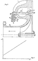
- a high-pressure body 1 conveys the fluid to introduce it radially by an injection sector 2 extending, in this example, over an arc of approximately 140 °.
- This injection sector 2 comprises, in the central zone, three fixed guide vanes 3, a first group of four guide vanes 4A, 5A, 6A, 7A each orientable by rotation around a pivot 4P, 5P, 6P, 7P and each controlled by an arm 4B, 5B, 6B, 7B secured at dawn and terminated by a roller 4R, 5R, 6R, 7R.
- These rollers are guided by a groove 8 formed in a control ring 9 concentric with a discharge cylinder 10 whose axis coincides with that of the machine.
- This injection sector 2 also includes a second group with three guide vanes IIA, 12A, 13A each orientable by rotation around a pivot 11P, 12P, 13P, each controlled by an arm 11B, 12B, 13B secured at dawn and ended with a roller 11R, 12R, 13R.
- These rollers 11R, 12R, 13R are guided respectively by the grooves 14, 15, 16 of the control ring 9 which, by means of a linkage 17, is actuated by a servo motor not shown.
- FIG. 1 represents the injection sector 2 in the position corresponding to the minimum flow rate of the fluid. The latter is expanded by passing through the three channels formed by the three fixed guide vanes 3 and the orientable guide vane 11A.
- the control crown 9 rotates, clockwise, by an angle proportional to the increase in flow and the guide vanes orientable open successively and gradually depending on the position of the rollers on the ramps of the guide grooves.
- the steerable guide vane 4A gradually pivots according to the progression of the roller 4R on the ramp 8R of the groove 8 formed in the control crown 9.
- the orientable guide vane 11A begins its rotation before the total opening of the orientable guide vane 4A.
- the opening control of the adjustable guide vanes 4A, 5A, 6A is carried out by the single ramp 8R of the groove 8 while the opening control of the vanes 11A, 12A, 13A is made by the ramps 14R, 15R, 16R belonging respectively to the grooves 14, 15, 16 formed in the control ring 9.
- This control ring 9 consists of two co-axial plates 18, 19 of the same diameter, made integral with one another and carrying one 18 the guide grooves 8 and 15 and the other 19 the grooves of guidance 14 and 16.
- the injection sector may extend over a different arc from that shown in FIG. 1. It is even possible to obtain an injection of the fluid over an opening of the order of 360 °. It is also possible that the order of opening of the orientable guide vanes takes place according to another process. For example, contrary to FIG. 1 where the progressive opening of the injection sector is done by extension of a central zone widening on either side of a minimum opening, an opening can be made. progressive spreading on one side of the minimum opening.
- FIG. 3 represents the orientable guide vane 4A in the fully open position while the orientable guide vane 5A is still completely closed.
- all the blades have an aerodynamic profile in the shape of a very flat triangle.
- the base of this triangle determines with its long side an edge which is the trailing edge of the blade and with its short side another edge which constitutes the leading edge of the blade.
- the apex of the triangle is rounded according to a curvature concentric with the pivot of the blade so as to determine a range on which the trailing edge of the neighboring blade can bear. This range, called neutral zone, allows the neighboring blade to keep the same position whatever the orientation of the blade on which it rests.
- the orientable guide vane 5A rests by its trailing edge on the neutral zone of the guide vane orientable 4A. Therefore, the orientation of the steerable guide vane 4A can vary without changing the orientation of the steerable guide vane 5A.
- This configuration makes it possible not to create parasitic openings, generating eddies which modify the flow of the fluid and reduce the efficiency of the fluid expansion.
- FIG. 3 also shows an implantation of the pivots of the orientable guide vanes on the high-pressure body 1 so as to form converging channels, whatever the degree of opening of the vanes, to allow suitable relaxation of the fluids conveyed.
- the steerable guide vanes shown in Figure 3 have two wings which, counted from the axis of the pivot of the blade, are of unequal sizes. This asymmetry allows by the play of pressures applied to the different faces of the triangle to obtain a resulting torque always acting in the same direction and to allow on the one hand to the whole linkage to work without shaking and on the other hand to the roller, located at the end of the arm, to remain applied to the same flank of the groove made in the control ring 9.
- the result of the forces acting on the different forces of the orientable guide vane 6A results in a torque acting in the anticlockwise to apply the roller 6R on the lower side of the groove 8.
- the regulator with variable injection sector equips the high-pressure body with a centriped turbine. It is obvious that the same device can equip both the high and low pressure bodies of this turbine.
Landscapes
- Engineering & Computer Science (AREA)
- Mechanical Engineering (AREA)
- General Engineering & Computer Science (AREA)
- Control Of Turbines (AREA)
- Structures Of Non-Positive Displacement Pumps (AREA)
- Superconductors And Manufacturing Methods Therefor (AREA)
- Turbine Rotor Nozzle Sealing (AREA)
- Supercharger (AREA)
Priority Applications (4)
| Application Number | Priority Date | Filing Date | Title |
|---|---|---|---|
| EP81870007A EP0056569A1 (de) | 1981-01-21 | 1981-01-21 | Turbine mit regelbarem Einlassquerschnitt |
| AT82200035T ATE23905T1 (de) | 1981-01-21 | 1982-01-14 | Turbine mit regelbarem einlassquerschnitt. |
| DE8282200035T DE3274480D1 (en) | 1981-01-21 | 1982-01-14 | Turbine with variable inlet section |
| EP82200035A EP0056669B1 (de) | 1981-01-21 | 1982-01-14 | Turbine mit regelbarem Einlassquerschnitt |
Applications Claiming Priority (1)
| Application Number | Priority Date | Filing Date | Title |
|---|---|---|---|
| EP81870007A EP0056569A1 (de) | 1981-01-21 | 1981-01-21 | Turbine mit regelbarem Einlassquerschnitt |
Publications (1)
| Publication Number | Publication Date |
|---|---|
| EP0056569A1 true EP0056569A1 (de) | 1982-07-28 |
Family
ID=8188745
Family Applications (2)
| Application Number | Title | Priority Date | Filing Date |
|---|---|---|---|
| EP81870007A Withdrawn EP0056569A1 (de) | 1981-01-21 | 1981-01-21 | Turbine mit regelbarem Einlassquerschnitt |
| EP82200035A Expired EP0056669B1 (de) | 1981-01-21 | 1982-01-14 | Turbine mit regelbarem Einlassquerschnitt |
Family Applications After (1)
| Application Number | Title | Priority Date | Filing Date |
|---|---|---|---|
| EP82200035A Expired EP0056669B1 (de) | 1981-01-21 | 1982-01-14 | Turbine mit regelbarem Einlassquerschnitt |
Country Status (3)
| Country | Link |
|---|---|
| EP (2) | EP0056569A1 (de) |
| AT (1) | ATE23905T1 (de) |
| DE (1) | DE3274480D1 (de) |
Cited By (1)
| Publication number | Priority date | Publication date | Assignee | Title |
|---|---|---|---|---|
| WO2001011197A1 (en) * | 1999-08-05 | 2001-02-15 | Borgwarner, Inc. | Turbine guide vane for exhaust gas turbocharger |
Families Citing this family (5)
| Publication number | Priority date | Publication date | Assignee | Title |
|---|---|---|---|---|
| JPH01227823A (ja) * | 1988-03-08 | 1989-09-12 | Honda Motor Co Ltd | タービンの可変ノズル構造 |
| DE19741992A1 (de) * | 1997-09-24 | 1999-03-25 | Voith Hydro Gmbh & Co Kg | Strömungsmaschine, insbesondere Wasserturbine |
| AT411615B (de) * | 2000-10-31 | 2004-03-25 | Blank Otto Ing | Abgasturbolader für eine brennkraftmaschine |
| DE102008004014A1 (de) * | 2008-01-11 | 2009-07-23 | Continental Automotive Gmbh | Leitschaufel für eine variable Turbinengeometrie |
| DE102009057987B4 (de) * | 2009-12-11 | 2020-08-20 | BMTS Technology GmbH & Co. KG | Ladeeinrichtung und Leitschaufel für eine derartige Ladeeinrichtung |
Citations (12)
| Publication number | Priority date | Publication date | Assignee | Title |
|---|---|---|---|---|
| FR918317A (fr) * | 1945-08-10 | 1947-02-05 | Brandt Edgar Ets | Turbo-soufflante à gaz d'échappement alimentant un moteur à combustion interne à grande variation de vitesse |
| CH254459A (de) * | 1945-03-02 | 1948-04-30 | Berger Hans | Abgasturbolader. |
| GB704351A (en) * | 1951-03-21 | 1954-02-17 | Alan Muntz & Co Ltd | Improvements in and relating to turbines operated by gases supplied by free-piston gas-generators |
| GB731822A (en) * | 1952-03-14 | 1955-06-15 | Power Jets Res & Dev Ltd | Improvements relating to turbines or compressors for operation with gaseous fluids |
| US2985427A (en) * | 1955-11-25 | 1961-05-23 | Gen Electric | Adjustable blading for fluid flow machines |
| US3029067A (en) * | 1956-05-31 | 1962-04-10 | Garrett Corp | Variable area nozzle means for turbines |
| US3243159A (en) * | 1964-04-27 | 1966-03-29 | Ingersoll Rand Co | Guide vane mechanism for centrifugal fluid-flow machines |
| FR2064617A5 (de) * | 1969-09-22 | 1971-07-23 | Garrett Corp | |
| FR2162662A1 (de) * | 1971-12-11 | 1973-07-20 | Lucas Aerospace Ltd | |
| US3799689A (en) * | 1971-05-14 | 1974-03-26 | Hitachi Ltd | Operating apparatus for guide vanes of hydraulic machine |
| US4179247A (en) * | 1977-01-14 | 1979-12-18 | Wrr Industries, Inc. | Turbocharger having variable area turbine nozzles |
| EP0009843A1 (de) * | 1978-10-05 | 1980-04-16 | ATELIERS DE CONSTRUCTIONS ELECTRIQUES DE CHARLEROI (ACEC) Société Anonyme | Entspannungsturbinen-Generator-Einheit |
-
1981
- 1981-01-21 EP EP81870007A patent/EP0056569A1/de not_active Withdrawn
-
1982
- 1982-01-14 DE DE8282200035T patent/DE3274480D1/de not_active Expired
- 1982-01-14 AT AT82200035T patent/ATE23905T1/de not_active IP Right Cessation
- 1982-01-14 EP EP82200035A patent/EP0056669B1/de not_active Expired
Patent Citations (12)
| Publication number | Priority date | Publication date | Assignee | Title |
|---|---|---|---|---|
| CH254459A (de) * | 1945-03-02 | 1948-04-30 | Berger Hans | Abgasturbolader. |
| FR918317A (fr) * | 1945-08-10 | 1947-02-05 | Brandt Edgar Ets | Turbo-soufflante à gaz d'échappement alimentant un moteur à combustion interne à grande variation de vitesse |
| GB704351A (en) * | 1951-03-21 | 1954-02-17 | Alan Muntz & Co Ltd | Improvements in and relating to turbines operated by gases supplied by free-piston gas-generators |
| GB731822A (en) * | 1952-03-14 | 1955-06-15 | Power Jets Res & Dev Ltd | Improvements relating to turbines or compressors for operation with gaseous fluids |
| US2985427A (en) * | 1955-11-25 | 1961-05-23 | Gen Electric | Adjustable blading for fluid flow machines |
| US3029067A (en) * | 1956-05-31 | 1962-04-10 | Garrett Corp | Variable area nozzle means for turbines |
| US3243159A (en) * | 1964-04-27 | 1966-03-29 | Ingersoll Rand Co | Guide vane mechanism for centrifugal fluid-flow machines |
| FR2064617A5 (de) * | 1969-09-22 | 1971-07-23 | Garrett Corp | |
| US3799689A (en) * | 1971-05-14 | 1974-03-26 | Hitachi Ltd | Operating apparatus for guide vanes of hydraulic machine |
| FR2162662A1 (de) * | 1971-12-11 | 1973-07-20 | Lucas Aerospace Ltd | |
| US4179247A (en) * | 1977-01-14 | 1979-12-18 | Wrr Industries, Inc. | Turbocharger having variable area turbine nozzles |
| EP0009843A1 (de) * | 1978-10-05 | 1980-04-16 | ATELIERS DE CONSTRUCTIONS ELECTRIQUES DE CHARLEROI (ACEC) Société Anonyme | Entspannungsturbinen-Generator-Einheit |
Cited By (1)
| Publication number | Priority date | Publication date | Assignee | Title |
|---|---|---|---|---|
| WO2001011197A1 (en) * | 1999-08-05 | 2001-02-15 | Borgwarner, Inc. | Turbine guide vane for exhaust gas turbocharger |
Also Published As
| Publication number | Publication date |
|---|---|
| EP0056669A1 (de) | 1982-07-28 |
| DE3274480D1 (en) | 1987-01-15 |
| ATE23905T1 (de) | 1986-12-15 |
| EP0056669B1 (de) | 1986-11-26 |
Similar Documents
| Publication | Publication Date | Title |
|---|---|---|
| FR2534222A1 (fr) | Agencement de rotor de queue a poussee accrue pour aeronef a voilure tournante et dispositif pour accroitre la poussee d'un tel agencement | |
| FR2688543A1 (fr) | Appareil reglable de guidage de l'ecoulement pour une turbine de turbocompresseur a gaz d'echappement. | |
| WO2009156600A1 (fr) | Injection d'air dans la veine d'un compresseur de turbomachine | |
| EP0023172B1 (de) | Ventil mit Schwingungsunterdrückung | |
| FR2862723A1 (fr) | Turbine et centrale hydraulique pour tres basse chute | |
| EP0394140B1 (de) | Fluidumlauf- und -verteilergerät | |
| EP0056669B1 (de) | Turbine mit regelbarem Einlassquerschnitt | |
| EP2984374B1 (de) | Ventil, insbesondere motorsteuerventil, mit einem dosierschieber und einem ablenkschieber | |
| FR3001005A1 (fr) | Groupe motocompresseur a profil aerodynamique variable | |
| FR2858027A1 (fr) | Compresseur haute pression a cycle hybride et turbomachine comprenant un tel compresseur | |
| FR2956454A1 (fr) | Aube a angle de calage variable pour la prevention du decollement. | |
| EP0698739A1 (de) | Abblassvorrichtung für Turbomaschine | |
| FR2626322A1 (fr) | Roue a ailettes de compresseur centrifuge | |
| FR2473624A1 (fr) | Tubulure d'echappement de turbine | |
| FR2468002A1 (fr) | Eolienne a ailes deformables | |
| FR2488337A1 (fr) | Eolienne a roues multiples d'axe horizontal, carenees et juxtaposees | |
| FR3006010A1 (fr) | Partie tournante de machine hydraulique, machine hydraulique equipee d'une telle partie tournante et installation de conversion d'energie comprenant une telle machine | |
| EP0179078B1 (de) | Hydraulische Turbine mit teilweise trockenlaufendem Laufrad und Injektor | |
| CA2812691C (fr) | Dispositif hydraulique d'un dispositif de commande tel qu'un dispositif de changement de pas d'helice | |
| EP3209881B1 (de) | Wasserturbine, hubtor für eine schleuse umfassend die genannte turbine und verfahren zur verstromung der hydraulischen energie mit derern hilfe | |
| EP2986877A1 (de) | Ventil, insbesondere motorsteuerventil, mit einem dosierschieber und einem ablenkschieber | |
| FR2602550A1 (fr) | Turbomoteur a double flux a tuyere confluente variable | |
| BE501076A (de) | ||
| EP0043305A1 (de) | Turbine mit regelbarem Spiralgehäuse für die Gaszufuhr | |
| FR3093136A1 (fr) | Carter d’entree pour une turbomachine d’aeronef |
Legal Events
| Date | Code | Title | Description |
|---|---|---|---|
| PUAI | Public reference made under article 153(3) epc to a published international application that has entered the european phase |
Free format text: ORIGINAL CODE: 0009012 |
|
| 17P | Request for examination filed |
Effective date: 19811030 |
|
| AK | Designated contracting states |
Designated state(s): AT BE CH DE FR GB IT LI LU NL SE |
|
| RAP1 | Party data changed (applicant data changed or rights of an application transferred) |
Owner name: ATELIERS DE CONSTRUCTIONS ELECTRIQUES DE CHARLEROI |
|
| STAA | Information on the status of an ep patent application or granted ep patent |
Free format text: STATUS: THE APPLICATION IS DEEMED TO BE WITHDRAWN |
|
| 18D | Application deemed to be withdrawn |
Effective date: 19831117 |
|
| RIN1 | Information on inventor provided before grant (corrected) |
Inventor name: WATTEZ, RAYMOND Inventor name: VAN GUCHT, ALBERT |