EP0056532B1 - Vorrichtung und Verfahren zum diagonalen Einstellen einer Offset-Druckmaschine und Druckmaschine mit dieser Vorrichtung - Google Patents
Vorrichtung und Verfahren zum diagonalen Einstellen einer Offset-Druckmaschine und Druckmaschine mit dieser Vorrichtung Download PDFInfo
- Publication number
- EP0056532B1 EP0056532B1 EP19810400066 EP81400066A EP0056532B1 EP 0056532 B1 EP0056532 B1 EP 0056532B1 EP 19810400066 EP19810400066 EP 19810400066 EP 81400066 A EP81400066 A EP 81400066A EP 0056532 B1 EP0056532 B1 EP 0056532B1
- Authority
- EP
- European Patent Office
- Prior art keywords
- cylinder
- blanket
- plate
- eccentric
- blanket cylinder
- Prior art date
- Legal status (The legal status is an assumption and is not a legal conclusion. Google has not performed a legal analysis and makes no representation as to the accuracy of the status listed.)
- Expired
Links
Images

Classifications
-
- B—PERFORMING OPERATIONS; TRANSPORTING
- B41—PRINTING; LINING MACHINES; TYPEWRITERS; STAMPS
- B41F—PRINTING MACHINES OR PRESSES
- B41F13/00—Common details of rotary presses or machines
- B41F13/08—Cylinders
- B41F13/24—Cylinder-tripping devices; Cylinder-impression adjustments
- B41F13/26—Arrangement of cylinder bearings
- B41F13/28—Bearings mounted eccentrically of the cylinder axis
Definitions
- the present invention relates to a "crooked" correction method in an offset printing machine; it also relates to the device used for this purpose, and to a printing machine comprising such a device.
- the plate or plate is fixed on a cylinder called plate cylinder, where it is wet and inked by contact with rollers themselves in contact with distribution rollers.
- the ink selectively deposited on the plate is distributed over an intermediate cylinder called the blanket cylinder, and from there is deposited on the sheet of paper which passes in contact with the blanket cylinder.
- the blanket cylinder is normally strictly parallel. If printing takes place on only one side of the paper, the sheet is applied in contact with the blanket by a pressure counter-cylinder; very frequently for two-sided printing machines, another inking assembly with plate cylinder and blanket is disposed approximately symmetrically with respect to the first, and the sheet circulates between the two blanket cylinders, each providing back pressure for the other.
- the plate plate is fixed and tensioned by a usual device arranged according to a generator of the plate cylinder.
- the machines comprise a device for adjusting the circumferential and lateral register, allowing an angular and axial relative offset of the plate cylinder with respect to the general drive kinematic chain of the machine, so as to allow in particular the location colors on machines with several printing stations.
- a correction is sometimes made by acting on the plate cylinder to put it slightly at an angle to the blanket cylinder, so as to thus restore the correct position of the image formed on the plate relative to the blanket.
- This means of correcting the "cross” obviously makes it possible to act in operation, if care has been taken to mount at least one of the bearings of the plate cylinder on an eccentric housing.
- the bearings of the plate cylinders generally comprising the mechanisms for adjusting the circumferential and lateral markings, already bulky mechanisms, so that it proves difficult and complex, and consequently expensive to add an additional device for biasing by independent movement of one of the bearings.
- the skew movement of the plate cylinder leads to an adjustment of the contact of the inking and wetting rollers, and to remedy this new drawback it would be necessary to introduce other devices, again bulky and expensive.
- the present invention provides a new solution for the correction on the fly of the consequences of a "skewed" defect in photographs.
- the invention relates to a "crooked" correction method in a rotary offset printing machine comprising at least one assembly of a plate plate plate cylinder and a blanket cylinder in contact with the sheet to be printed, method intended to compensate a slight misalignment of the plate formed on the plate.
- action is taken by angularly displacing the axis of the blanket cylinder with respect to the axis of the plate cylinder, this displacement being effected substantially in a plane perpendicular to the plane containing the two parallel axes in their normal mean position.
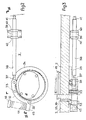
- the invention also relates to a device for implementing this correction method, applied to a machine where the journals of the blanket cylinders are carried by eccentric bearings associated with a device for controlling the rotation of these eccentric bearings, to separate or bring the blanket closer to the sheet to be printed.
Claims (3)
Priority Applications (2)
| Application Number | Priority Date | Filing Date | Title |
|---|---|---|---|
| EP19810400066 EP0056532B1 (de) | 1981-01-19 | 1981-01-19 | Vorrichtung und Verfahren zum diagonalen Einstellen einer Offset-Druckmaschine und Druckmaschine mit dieser Vorrichtung |
| DE8181400066T DE3165298D1 (en) | 1981-01-19 | 1981-01-19 | Method and means for diagonal adjustment in an offset-printing machine, and printing machine produced with said means |
Applications Claiming Priority (1)
| Application Number | Priority Date | Filing Date | Title |
|---|---|---|---|
| EP19810400066 EP0056532B1 (de) | 1981-01-19 | 1981-01-19 | Vorrichtung und Verfahren zum diagonalen Einstellen einer Offset-Druckmaschine und Druckmaschine mit dieser Vorrichtung |
Publications (2)
| Publication Number | Publication Date |
|---|---|
| EP0056532A1 EP0056532A1 (de) | 1982-07-28 |
| EP0056532B1 true EP0056532B1 (de) | 1984-08-08 |
Family
ID=8188497
Family Applications (1)
| Application Number | Title | Priority Date | Filing Date |
|---|---|---|---|
| EP19810400066 Expired EP0056532B1 (de) | 1981-01-19 | 1981-01-19 | Vorrichtung und Verfahren zum diagonalen Einstellen einer Offset-Druckmaschine und Druckmaschine mit dieser Vorrichtung |
Country Status (2)
| Country | Link |
|---|---|
| EP (1) | EP0056532B1 (de) |
| DE (1) | DE3165298D1 (de) |
Families Citing this family (1)
| Publication number | Priority date | Publication date | Assignee | Title |
|---|---|---|---|---|
| JPS63226689A (ja) * | 1986-10-17 | 1988-09-21 | 林 顕 | 発音用振動板 |
Family Cites Families (2)
| Publication number | Priority date | Publication date | Assignee | Title |
|---|---|---|---|---|
| CH382766A (de) * | 1959-04-08 | 1964-10-15 | Maschf Augsburg Nuernberg Ag | Einrichtung zum Einstellen der Zylinder von Offsetmaschinen |
| US3817173A (en) * | 1971-09-13 | 1974-06-18 | Polygraph Leipzig | Diagonal register adjustment of plate cylinder and applicator rolls in a rotary printing machine |
-
1981
- 1981-01-19 DE DE8181400066T patent/DE3165298D1/de not_active Expired
- 1981-01-19 EP EP19810400066 patent/EP0056532B1/de not_active Expired
Also Published As
| Publication number | Publication date |
|---|---|
| EP0056532A1 (de) | 1982-07-28 |
| DE3165298D1 (en) | 1984-09-13 |
Similar Documents
| Publication | Publication Date | Title |
|---|---|---|
| EP0305235B1 (de) | Abnehmbare Druckeinheit für Offsetdruckmaschinen | |
| JP4413422B2 (ja) | 可変性カットオフ印刷機 | |
| FR1464341A (fr) | Presses imprimantes rotatives à bobines | |
| EP1754599B1 (de) | Druckeinheit mit einem druckan- bzw. druckabstellbaren Gummizylinder und entsprechende Druckmaschine | |
| FR2735419A1 (fr) | Dispositif d'entrainement direct pour une machine d'impression | |
| US5746132A (en) | Variable repeat plate and blanket cylinder mechanism | |
| JPH0667617B2 (ja) | 枚葉紙輪転印刷機のドラム又は胴のための伝動装置 | |
| US3769910A (en) | Movably positionable cylinder arrangement for indirect printing presses | |
| EP0056532B1 (de) | Vorrichtung und Verfahren zum diagonalen Einstellen einer Offset-Druckmaschine und Druckmaschine mit dieser Vorrichtung | |
| FR2469283A1 (fr) | Procede et dispositif de correction dite " de travers " dans une machine a imprimer offset, et machine a imprimer comportant un tel dispositif | |
| US7089858B2 (en) | Rotary press | |
| US6601504B2 (en) | Cylinder apparatus for rotary printing press | |
| EP2121326B1 (de) | Zahnradgetriebene druckmaschine mit variabler abstellung | |
| US4833988A (en) | Inking device for printing apparatus | |
| JPH08506284A (ja) | 印刷機における胴の軸間距離調整装置 | |
| KR100232909B1 (ko) | 고무통의 인쇄압을 가하고 제거하기 위한 장치 | |
| FR2538760A1 (fr) | Mecanisme d'encrage pour machines a imprimer rotatives | |
| FR2725663A1 (fr) | Montage de cylindre porte-plaque | |
| JPH02274544A (ja) | インキ装置と湿し装置とを連結させる中間ローラ対の第2中間ローラを置換えるための装置 | |
| EP0824068B1 (de) | Aufhebung des Zahnspiels im Antrieb einer Druckmaschine | |
| US20110132216A1 (en) | Stack angle compensation arrangement for a skewing adjustment system in an offset printing press | |
| FR2527518A1 (fr) | Machine a imprimer dont les cylindres comportent des bagues d'espacement | |
| FR2741294A1 (fr) | Dispositif de reglage pour des cylindres d'une unite d'impression | |
| JPS6213800Y2 (de) | ||
| JPH0726109Y2 (ja) | 印刷機の駆動機構 |
Legal Events
| Date | Code | Title | Description |
|---|---|---|---|
| PUAI | Public reference made under article 153(3) epc to a published international application that has entered the european phase |
Free format text: ORIGINAL CODE: 0009012 |
|
| 17P | Request for examination filed |
Effective date: 19811028 |
|
| AK | Designated contracting states |
Designated state(s): BE CH DE GB |
|
| GRAA | (expected) grant |
Free format text: ORIGINAL CODE: 0009210 |
|
| AK | Designated contracting states |
Designated state(s): BE CH DE GB LI |
|
| REF | Corresponds to: |
Ref document number: 3165298 Country of ref document: DE Date of ref document: 19840913 |
|
| PGFP | Annual fee paid to national office [announced via postgrant information from national office to epo] |
Ref country code: DE Payment date: 19850328 Year of fee payment: 5 |
|
| PLBE | No opposition filed within time limit |
Free format text: ORIGINAL CODE: 0009261 |
|
| STAA | Information on the status of an ep patent application or granted ep patent |
Free format text: STATUS: NO OPPOSITION FILED WITHIN TIME LIMIT |
|
| 26N | No opposition filed | ||
| PG25 | Lapsed in a contracting state [announced via postgrant information from national office to epo] |
Ref country code: LI Effective date: 19880131 Ref country code: CH Effective date: 19880131 |
|
| BERE | Be: lapsed |
Owner name: CREUSOT-LOIRE Effective date: 19880131 |
|
| GBPC | Gb: european patent ceased through non-payment of renewal fee | ||
| REG | Reference to a national code |
Ref country code: CH Ref legal event code: PL |
|
| PG25 | Lapsed in a contracting state [announced via postgrant information from national office to epo] |
Ref country code: DE Effective date: 19881001 |
|
| REG | Reference to a national code |
Ref country code: CH Ref legal event code: AUV Free format text: TOMBE EN DECHEANCE 23.08.1988 FAUTE DE PAIEMENT, DE LA 8E ANNUITE. |
|
| PG25 | Lapsed in a contracting state [announced via postgrant information from national office to epo] |
Ref country code: GB Free format text: LAPSE BECAUSE OF NON-PAYMENT OF DUE FEES Effective date: 19881121 |
|
| PG25 | Lapsed in a contracting state [announced via postgrant information from national office to epo] |
Ref country code: BE Effective date: 19890131 |