EP0056532B1 - Method and means for diagonal adjustment in an offset-printing machine, and printing machine produced with said means - Google Patents
Method and means for diagonal adjustment in an offset-printing machine, and printing machine produced with said means Download PDFInfo
- Publication number
- EP0056532B1 EP0056532B1 EP19810400066 EP81400066A EP0056532B1 EP 0056532 B1 EP0056532 B1 EP 0056532B1 EP 19810400066 EP19810400066 EP 19810400066 EP 81400066 A EP81400066 A EP 81400066A EP 0056532 B1 EP0056532 B1 EP 0056532B1
- Authority
- EP
- European Patent Office
- Prior art keywords
- cylinder
- blanket
- plate
- eccentric
- blanket cylinder
- Prior art date
- Legal status (The legal status is an assumption and is not a legal conclusion. Google has not performed a legal analysis and makes no representation as to the accuracy of the status listed.)
- Expired
Links
Images

Classifications
-
- B—PERFORMING OPERATIONS; TRANSPORTING
- B41—PRINTING; LINING MACHINES; TYPEWRITERS; STAMPS
- B41F—PRINTING MACHINES OR PRESSES
- B41F13/00—Common details of rotary presses or machines
- B41F13/08—Cylinders
- B41F13/24—Cylinder-tripping devices; Cylinder-impression adjustments
- B41F13/26—Arrangement of cylinder bearings
- B41F13/28—Bearings mounted eccentrically of the cylinder axis
Definitions
- the present invention relates to a "crooked" correction method in an offset printing machine; it also relates to the device used for this purpose, and to a printing machine comprising such a device.
- the plate or plate is fixed on a cylinder called plate cylinder, where it is wet and inked by contact with rollers themselves in contact with distribution rollers.
- the ink selectively deposited on the plate is distributed over an intermediate cylinder called the blanket cylinder, and from there is deposited on the sheet of paper which passes in contact with the blanket cylinder.
- the blanket cylinder is normally strictly parallel. If printing takes place on only one side of the paper, the sheet is applied in contact with the blanket by a pressure counter-cylinder; very frequently for two-sided printing machines, another inking assembly with plate cylinder and blanket is disposed approximately symmetrically with respect to the first, and the sheet circulates between the two blanket cylinders, each providing back pressure for the other.
- the plate plate is fixed and tensioned by a usual device arranged according to a generator of the plate cylinder.
- the machines comprise a device for adjusting the circumferential and lateral register, allowing an angular and axial relative offset of the plate cylinder with respect to the general drive kinematic chain of the machine, so as to allow in particular the location colors on machines with several printing stations.
- a correction is sometimes made by acting on the plate cylinder to put it slightly at an angle to the blanket cylinder, so as to thus restore the correct position of the image formed on the plate relative to the blanket.
- This means of correcting the "cross” obviously makes it possible to act in operation, if care has been taken to mount at least one of the bearings of the plate cylinder on an eccentric housing.
- the bearings of the plate cylinders generally comprising the mechanisms for adjusting the circumferential and lateral markings, already bulky mechanisms, so that it proves difficult and complex, and consequently expensive to add an additional device for biasing by independent movement of one of the bearings.
- the skew movement of the plate cylinder leads to an adjustment of the contact of the inking and wetting rollers, and to remedy this new drawback it would be necessary to introduce other devices, again bulky and expensive.
- the present invention provides a new solution for the correction on the fly of the consequences of a "skewed" defect in photographs.
- the invention relates to a "crooked" correction method in a rotary offset printing machine comprising at least one assembly of a plate plate plate cylinder and a blanket cylinder in contact with the sheet to be printed, method intended to compensate a slight misalignment of the plate formed on the plate.
- action is taken by angularly displacing the axis of the blanket cylinder with respect to the axis of the plate cylinder, this displacement being effected substantially in a plane perpendicular to the plane containing the two parallel axes in their normal mean position.
- the invention also relates to a device for implementing this correction method, applied to a machine where the journals of the blanket cylinders are carried by eccentric bearings associated with a device for controlling the rotation of these eccentric bearings, to separate or bring the blanket closer to the sheet to be printed.
Description
La présente invention concerne un procédé de correction "de travers" dans une machine à imprimer offset; elle concerne aussi le dispositif utilisé à cet effet, et une machine à imprimer comportant un tel dispositif.The present invention relates to a "crooked" correction method in an offset printing machine; it also relates to the device used for this purpose, and to a printing machine comprising such a device.
Dans une machine d'impression offset, le cliché ou plaque est fixé sur un cylindre dit cylindre de plaque, où il est mouillé et encré par contact avec des rouleaux eux-mêmes en contact avec des rouleaux de répartition. L'encre sélectivement déposée sur le cliché est répartie sur un cylindre intermédiaire dit cylindre blanchet, et de là est déposée sur la feuille de papier qui défile en contact avec le cylindre blanchet. Bien entendu les axes du cylindre blanchet et du cylindre de plaque sont normalement strictement parallèles. Si l'impression n'a lieu que sur une seule face du papier la feuille est appliquée au contact du blanchet par un contre-cylindre de pression; très fréquemment pour des machines à imprimer recto verso, un autre ensemble d'encrage avec cylindre de plaque et blanchet est disposé à peu près symétriquement par rapport au premier, et la feuille circule entre les deux cylindres blanchet, chacun assurant la contre-pression pour l'autre. La plaque cliché est fixée et tendue par un dispositif usuel disposé selon une génératrice du cylindre de plaque. De façon usuelle également les machines comportent un dispositif de réglage de registre circonférentiel et latéral, permettant un décalage relatif angulaire et axial du cylindre de plaque par rapport à la chaîne cinématique d'entrainement général de la machine, de façon à permettre en particulier le repérage des couleurs sur les machines à plusieurs postes d'impression.In an offset printing machine, the plate or plate is fixed on a cylinder called plate cylinder, where it is wet and inked by contact with rollers themselves in contact with distribution rollers. The ink selectively deposited on the plate is distributed over an intermediate cylinder called the blanket cylinder, and from there is deposited on the sheet of paper which passes in contact with the blanket cylinder. Of course the axes of the blanket cylinder and the plate cylinder are normally strictly parallel. If printing takes place on only one side of the paper, the sheet is applied in contact with the blanket by a pressure counter-cylinder; very frequently for two-sided printing machines, another inking assembly with plate cylinder and blanket is disposed approximately symmetrically with respect to the first, and the sheet circulates between the two blanket cylinders, each providing back pressure for the other. The plate plate is fixed and tensioned by a usual device arranged according to a generator of the plate cylinder. In a usual manner also, the machines comprise a device for adjusting the circumferential and lateral register, allowing an angular and axial relative offset of the plate cylinder with respect to the general drive kinematic chain of the machine, so as to allow in particular the location colors on machines with several printing stations.
Quel que soit le soin apporté à la confection des plaques clichés, il survient assez souvent un défaut dit "de travers", lorsque l'image sur le cliché n'est pas formée strictement selon l'axe du cliché. On peut arriver à compenser ce défaut lors de la mise en place de la plaque sur le cylindre de plaque, en disposant celle-ci légèrement en biais de telle sorte qu'elle est alors enroulée légèrement en hélice sur le cylindre. Mais ce réglage n'est évidemment pas possible en marche, alors que très souvent le défaut de travers n'est décelé qu'après la mise en place du cliché, lorsqu'on vérifie les premières impressions.Whatever care is taken in making the plates, quite often a so-called "skew" defect occurs when the image on the plate is not formed strictly along the axis of the plate. It is possible to compensate for this defect during the positioning of the plate on the plate cylinder, by placing it slightly at an angle so that it is then wound slightly helically on the cylinder. But this adjustment is obviously not possible when running, while very often the defect in the skew is not detected until after the installation of the plate, when we check the first impressions.
On procède parfois à une correction en agissant sur le cylindre de plaque pour le mettre légèrement en biais par rapport au cylindre blanchet, de façon à rétablir ainsi la position correcte de l'image formée sur le cliché par rapport au blanchet. Ce moyen de correction du "travers" permet évidemment d'agir en marche, si l'on a pris le soin de monter l'un au moins des paliers du cylindre de plaque sur un boîtier excentré. Mais les paliers des cylindres de plaque comportant généralement les mécanismes de réglage des repérages circonférentiels et latéraux, mécanismes déjà encombrants, si bien qu'il se révèle difficile et complexe, et par conséquent onéreux d'y ajouter un dispositif supplémentaire de mise en biais par déplacement indépendant de l'un des paliers. En outre, le déplacement en biais du cylindre de plaque entraine un déréglage du contact des rouleaux encreurs et mouilleurs, et pour remédier à ce nouvel inconvénient il faudrait introduire d'autres dispositifs, à nouveau encombrants et couteux.A correction is sometimes made by acting on the plate cylinder to put it slightly at an angle to the blanket cylinder, so as to thus restore the correct position of the image formed on the plate relative to the blanket. This means of correcting the "cross" obviously makes it possible to act in operation, if care has been taken to mount at least one of the bearings of the plate cylinder on an eccentric housing. But the bearings of the plate cylinders generally comprising the mechanisms for adjusting the circumferential and lateral markings, already bulky mechanisms, so that it proves difficult and complex, and consequently expensive to add an additional device for biasing by independent movement of one of the bearings. In addition, the skew movement of the plate cylinder leads to an adjustment of the contact of the inking and wetting rollers, and to remedy this new drawback it would be necessary to introduce other devices, again bulky and expensive.
Par ailleurs, on peut établir facilement que si un défaut "de travers" se traduit, pour un point du cliché, par un décalage linéaire a à l'une des extrémités du cylindre de plaque, par exemple en avance sur sa position théorique, le report sur le blanchet fait que l'on retrouve sur la feuille imprimée un décalage linéaire a de même valeur. Pour la correction le décalage linéaire de l'extrémité du cylindre de plaque devra être également de a, et le sinus de l'angle du décalage angulaire sera a/L, L étant la longueur de la table du cylindre. Les valeurs de a et L conduisent à imposer des roulements à rotule pour les paliers du cylindre pour pouvoir absorber de tels décalages angulaires. En outre un décalage angulaire excessif risque de réduire le jeu de denture des pignons d'entraînement, et de conduire à une usure anormale et prématurée de ceux-ci.Furthermore, it can be easily established that if a "skew" defect results, for a point in the picture, by a linear offset a at one of the ends of the plate cylinder, for example in advance of its theoretical position, the transfer to the blanket so that we find on the printed sheet a linear offset has the same value. For correction, the linear offset of the end of the plate cylinder must also be a, and the sine of the angle of the angular offset will be a / L, L being the length of the cylinder table. The values of a and L result in imposing spherical bearings for the bearings of the cylinder in order to be able to absorb such angular offsets. In addition, an excessive angular offset may reduce the backlash of the drive sprockets, and lead to abnormal and premature wear of the latter.
La présente invention apporte une solution nouvelle pour la correction en marche des conséquences d'un défaut "de travers" des clichés.The present invention provides a new solution for the correction on the fly of the consequences of a "skewed" defect in photographs.
L'invention concerne un procédé de correction "de travers" dans une machine rotative à imprimer offset comportant au moins un ensemble d'un cylindre de plaque support de plaque cliché et un cylindre blanchet au contact de la feuille à imprimer, procédé destiné à compenser un léger défaut d'alignement du cliché formé sur la plaque. Selon l'invention on agit en déplaçant angulairement l'axe du cylindre blanchet par rapport à l'axe du cylindre de plaque, ce déplacement étant effectué sensiblement dans un plan perpendiculaire au plan contenant les deux axes parallèles dans leur position moyenne normale.The invention relates to a "crooked" correction method in a rotary offset printing machine comprising at least one assembly of a plate plate plate cylinder and a blanket cylinder in contact with the sheet to be printed, method intended to compensate a slight misalignment of the plate formed on the plate. According to the invention, action is taken by angularly displacing the axis of the blanket cylinder with respect to the axis of the plate cylinder, this displacement being effected substantially in a plane perpendicular to the plane containing the two parallel axes in their normal mean position.
L'invention concerne également un dispositif pour la mise en oeuvre de ce procédé de correction, appliqué à une machine où les tourillons des cylindres de blanchet sont portés par des paliers excentrés associés à un dispositif de commande de rotation de ces paliers excentrés, pour écarter ou rapprocher le blanchet de la feuille à imprimer.The invention also relates to a device for implementing this correction method, applied to a machine where the journals of the blanket cylinders are carried by eccentric bearings associated with a device for controlling the rotation of these eccentric bearings, to separate or bring the blanket closer to the sheet to be printed.
Selon l'invention les paliers excentrés des cylindres de blanchet sont eux-mêmes chacun portés par une douille excentrée engagée dans un alésage du bâti; pour chaque cylindre de blanchet la douille excentrée relative à l'un des tourillons est maintenue fixe dans le bâti, tandis que l'autre est associée à un mécanisme de mise en rotation contrôlée, les positions relatives des centres des éléments excentrés de la douille étant déterminées de telle sorte que dans la plage normale de déplacement, le mouvement de l'axe du cylindre blanchet puisse rester assimilable à un mouvement dans un plan perpendiculaire au plan défini par les axes parallèles du cylindre blanchet et du cylindre de plaque en position normale moyenne.According to the invention the eccentric bearings of the blanket cylinders are themselves each carried by an eccentric sleeve engaged in a bore of the frame; for each blanket cylinder, the eccentric sleeve relative to one of the pins is kept fixed in the frame, while the other is associated with a controlled rotation mechanism, the relative positions of the centers of the eccentric elements of the sleeve being determined so that in the normal range of movement, the movement of the axis of the blanket cylinder can remain comparable to a movement in a plane perpendicular to the plane defined by the parallel axes of the blanket cylinder and of the plate cylinder in the normal normal position.
L'invention sera mieux comprise en se référant à un mode de réalisation particulier donné à titre d'exemple et représenté par les dessins annexés.The invention will be better understood by referring to a particular embodiment given by way of example and represented by the accompanying drawings.
La figure 1 donne le détail du montage des deux cylindres du blanchet dans les bâtis d'une machine à imprimer recto-verso comportant le dispositif de correction "de travers" selon l'invention.Figure 1 gives the detail of the mounting of the two blanket cylinders in the frames of a double-sided printing machine comprising the "skew" correction device according to the invention.
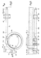
Les figures 2 et 3 montrent les organes de manoeuvre du dispositif de correction. La figure 2 est une vue partielle de face du bâti; la figure 3 est une vue selon III-III de la figure 2.Figures 2 and 3 show the actuators of the correction device. Figure 2 is a partial front view of the frame; FIG. 3 is a view along III-III of FIG. 2.
Sur la figure 1, où pour simplifier le dessin on a omis divers détails usuels comme les dispositifs de graissage des différents paliers, on verra en particulier les deux bâtis 1 et 2, respectivement côté entrainement et côté conduite, qui supportent les deux cylindres de blanchet 3 et 4 associés chacun aux cylindres de plaque correspondants 5 et 6. Les cylindres de blanchet et de plaque recto-verso sont ici entraînés comme dans la demande de brevet français FR - A - 2.458.395 du même déposant. Ainsi le cylindre de blanchet inférieur 4 est directement entraîné à partir du cylindre de plaque 6 par le couple de pignons 8-9, tandis que le cylindre de blanchet supérieur 3 est directement entrainé à partir du cylindre de plaque 5 par les pignons 10-11, sans qu'il y ait engrènement des pignons 9 et 11. La transmission du mouvement du cylindre de plaque 6 au cylindre de plaque 5 est obtenue par les pignons intermédiaires 13 et 14 simplement centrés sur les tourillons des cylindres de blanchet 3 et 4, sans liaison positive en rotation.In Figure 1, where to simplify the drawing we have omitted various usual details such as the lubrication devices of the different bearings, we will see in particular the two
Le cylindre blanchet 4 est porté par les roulements 16 et 17, eux-mêmes chacun engagés dans un boîtier excentré 18 et 19. De même les roulements support du blanchet 3 sont tenus dans les boitiers excentrés 20 et 21. Ce montage sur boîtier excentré constitue une disposition usuelle sur de telles machines, et est utilisé pour pouvoir mettre hors pression les cylindres blanchet par exemple lors des arrêts de la machine. Pour celà un dispositif de commande non représenté fait tourner simultanément les deux boîtiers de chacun des tourillons pour produire un mouvement d'écartement ou de rapporchement parallèle des cylindres l'un par rapport à l'autre. Le dispositif peut également être utilisé pour régler la pression des cylindres blanchet l'un contre l'autre en fonction des caractéristiques de la feuille imprimée.The blanket cylinder 4 is carried by the
Selon la présente invention chacun des boîtiers excentrés 18, 19, 20 et 21 des paliers de cylindres blanchet est lui-même inclus dans une autre douille excentrée respectivement 24, 25, 26 et 27, engagées chacune dans un alésage des bâtis 1 ou 2. Du côté des mécanismes d'entrainement, les douilles 24 et 26 sont bloquées en rotation dans le bâti 1 par des vis entre cuir et chair 29 et 30. Côté conduite au contraire les douilles excentrées 25 et 27 peuvent être manoeuvrées en rotation par un dispositif plus visible sur les figures 2 et 3. On n'a représenté sur ces deux figures que le dispositif concernant le cylindre 4, mais bien entendu, l'autre cylindre blanchet 3 est muni d'un dispositif de commande en tous points identique.According to the present invention each of the
Une pièce 32 en forme de secteur annulaire est fixée par des vis 33 sur la collerette extérieure 34 de la douille 25. A l'une des extrémités la pièce 32 présente un lamage qui forme une chape avec la collerette 34, et une noix taraudée 36 est maintenue prisonnière dans la chape en restant librement articulée sur des tétons engagés dans des alésages correspondants de la pièce 32 et de la collerette 34. L'extrémité filetée 37 d'une tige de commande 38 est engagée dans la noix 36; la tige 38, qui peut tourner librement dans l'alésage d'un support 39 fixé au bâti, est bloquée en déplacement axial par deux bagues 40 qui viennent respectivement en butée sur l'une ou l'autre face du support 39. On voit qu'en faisant tourner la tige 38, au moyen d'une clé engagée sur son embout 41, on provoque le déplacement de la noix 36 sur la tige filetée 37, ce qui entraîne la rotation de la douille 25-34 par rapport au bâti. Un ressort 44, en appui sur un prolongement 45 de la pièce 32 et sur une butée 46 solidaire du bâti, permet un rattrapage de l'ensemble des jeux du dispositif.A
La position relative des centres des éléments excentrés de la douille est déterminée de telle sorte que dans la plage normale de déplacement le mouvement de l'axe du cylindre puisse être assimilé à un mouvement dans un plan perpendiculaire au plan défini par les axes du cylindre blanchet et du cylindre de plaque en position normale.The relative position of the centers of the eccentric elements of the sleeve is determined so that in the normal range of movement the movement of the cylinder axis can be assimilated to a movement in a plane perpendicular to the plane defined by the axes of the blanket cylinder and the plate cylinder in the normal position.
Ainsi, le déplacement angulaire du cylindre blanchet résultant de la rotation de la douille 25 est tel que les distances entre cylindres sont conservées, de telle sorte que le réglage de pression du cylindre de plaque sur le blanchet ou du blanchet sur la feuille ne sont pas affectés. En outre, le cylindre de plaque étant resté immobile, tout le réglage de mouillage et d'encrage est intégralement conservé.Thus, the angular displacement of the blanket cylinder resulting from the rotation of the
On pourra encore établir que, reprenant l'exemple cité plus haut d'un défaut de travers du cliché se traduisant par un décalage linéaire a à l'extrémité du cylindre de plaque, il suffit maintenant, lorsqu'on agit sur le cylindre blanchet au lieu d'agir sur le cylindre de plaque, d'un décalage linéaire de l'extrémité d'une valeur de a/2 pour ramener l'impression à sa place correcte sur la feuille. Ceci est très important car pour les valeurs usuelles du défaut a et de la longueur des tables de cylindres, le décalage angulaire de correction n'étant plus que de la moitié de ce qui aurait été nécessaire en agissant sur le cylindre de plaque, on pourra généralement se contenter de roulements normaux pour les paliers des cylindres de blanchet. On notera encore que les conséquences néfastes d'un tel décalage angulaire sur les jeux de denture sont également réduites de moitié.We can also establish that, taking the example cited above of a flaw in the cliché resulting in a linear offset a at the end of the plate cylinder, it suffices now, when acting on the blanket cylinder at instead of acting on the plate cylinder, a linear offset from the end by a value of a / 2 to bring the print back to its correct place on the sheet. This is very important because for the usual values of the defect a and of the length of the cylinder tables, the angular offset of correction being no more than the half of what would have been necessary by acting on the plate cylinder, we can generally be satisfied with normal bearings for the bearings of the blanket cylinders. It will also be noted that the harmful consequences of such an angular offset on the backlash are also halved.
Bien entendu, l'invention n'est pas strictement limitée au mode de réalisation qui a été décrit à titre d'exemple, mais elle couvre également les réalisations qui n'en diffèreraient que par des détails, par des variantes d'exécution ou par l'utilisation de moyens équivalents. En particulier, l'invention s'applique de la même façon qu'il s'agisse d'une machine à imprimer offset recto-verso ou recto seulement, les dispositifs utilisés étant identiques pour chaque cylindre de blanchet dans le cas d'une machine recto-verso.Of course, the invention is not strictly limited to the embodiment which has been described by way of example, but it also covers the embodiments which would differ from it only in details, in variant embodiments or in the use of equivalent means. In particular, the invention applies in the same way whether it is a double-sided or single-sided offset printing machine, the devices used being identical for each blanket cylinder in the case of a machine both sides.
Claims (3)
Priority Applications (2)
| Application Number | Priority Date | Filing Date | Title |
|---|---|---|---|
| EP19810400066 EP0056532B1 (en) | 1981-01-19 | 1981-01-19 | Method and means for diagonal adjustment in an offset-printing machine, and printing machine produced with said means |
| DE8181400066T DE3165298D1 (en) | 1981-01-19 | 1981-01-19 | Method and means for diagonal adjustment in an offset-printing machine, and printing machine produced with said means |
Applications Claiming Priority (1)
| Application Number | Priority Date | Filing Date | Title |
|---|---|---|---|
| EP19810400066 EP0056532B1 (en) | 1981-01-19 | 1981-01-19 | Method and means for diagonal adjustment in an offset-printing machine, and printing machine produced with said means |
Publications (2)
| Publication Number | Publication Date |
|---|---|
| EP0056532A1 EP0056532A1 (en) | 1982-07-28 |
| EP0056532B1 true EP0056532B1 (en) | 1984-08-08 |
Family
ID=8188497
Family Applications (1)
| Application Number | Title | Priority Date | Filing Date |
|---|---|---|---|
| EP19810400066 Expired EP0056532B1 (en) | 1981-01-19 | 1981-01-19 | Method and means for diagonal adjustment in an offset-printing machine, and printing machine produced with said means |
Country Status (2)
| Country | Link |
|---|---|
| EP (1) | EP0056532B1 (en) |
| DE (1) | DE3165298D1 (en) |
Families Citing this family (1)
| Publication number | Priority date | Publication date | Assignee | Title |
|---|---|---|---|---|
| JPS63226689A (en) * | 1986-10-17 | 1988-09-21 | 林 顕 | Sound generating diaphragm |
Family Cites Families (2)
| Publication number | Priority date | Publication date | Assignee | Title |
|---|---|---|---|---|
| CH382766A (en) * | 1959-04-08 | 1964-10-15 | Maschf Augsburg Nuernberg Ag | Device for adjusting the cylinders of offset machines |
| US3817173A (en) * | 1971-09-13 | 1974-06-18 | Polygraph Leipzig | Diagonal register adjustment of plate cylinder and applicator rolls in a rotary printing machine |
-
1981
- 1981-01-19 EP EP19810400066 patent/EP0056532B1/en not_active Expired
- 1981-01-19 DE DE8181400066T patent/DE3165298D1/en not_active Expired
Also Published As
| Publication number | Publication date |
|---|---|
| EP0056532A1 (en) | 1982-07-28 |
| DE3165298D1 (en) | 1984-09-13 |
Similar Documents
| Publication | Publication Date | Title |
|---|---|---|
| EP0305235B1 (en) | Removable printing unit for offset-printing presses | |
| JP4413422B2 (en) | Variable cut-off printing machine | |
| FR2747339A1 (en) | DRIVE DEVICE COMPRISING AN ALIGNMENT DEVICE FOR A PRINTING UNIT OF A ROTARY PRESS TO BE PRINTED | |
| EP1754599B1 (en) | Printing unit with blanket cylinder movable between a throw-on and a throw-off position and corresponding printing press | |
| FR2735419A1 (en) | DIRECT DRIVE DEVICE FOR A PRINTING MACHINE | |
| JPH0667617B2 (en) | Transmission for the drum or cylinder of a sheet-fed rotary printing press | |
| US3769910A (en) | Movably positionable cylinder arrangement for indirect printing presses | |
| EP0056532B1 (en) | Method and means for diagonal adjustment in an offset-printing machine, and printing machine produced with said means | |
| US3593662A (en) | Cylinder arrangement for an offset litho machine | |
| FR2469283A1 (en) | Offset printer roller support - has roller bearings housed in eccentric bush with pin to prevent rotation | |
| JP2726015B2 (en) | Printing cylinder position adjustment device with removable blanket | |
| US7089858B2 (en) | Rotary press | |
| US6601504B2 (en) | Cylinder apparatus for rotary printing press | |
| JPH09177903A (en) | Play removing device in printer | |
| EP2121326B1 (en) | Gear driven variable cutoff printing press | |
| US4833988A (en) | Inking device for printing apparatus | |
| JPH08506284A (en) | Cylinder axial distance adjustment device for printing machines | |
| KR100232909B1 (en) | Device for applying pressure to and withdrawing pressure from a cylinder | |
| FR2538760A1 (en) | INK MECHANISM FOR ROTARY PRINTING MACHINES | |
| FR2725663A1 (en) | PLATE HOLDER CYLINDER ASSEMBLY | |
| JPH02274544A (en) | Device for replacing second roller of pair of intermediate rolles connecting ink unit with damping unit | |
| EP0824068B1 (en) | Taking-up backlash in the drive unit of a printing press | |
| JP3296918B2 (en) | Phase adjustment mechanism | |
| US20110132216A1 (en) | Stack angle compensation arrangement for a skewing adjustment system in an offset printing press | |
| JPH07102672B2 (en) | Image position adjustment device for printing machine |
Legal Events
| Date | Code | Title | Description |
|---|---|---|---|
| PUAI | Public reference made under article 153(3) epc to a published international application that has entered the european phase |
Free format text: ORIGINAL CODE: 0009012 |
|
| 17P | Request for examination filed |
Effective date: 19811028 |
|
| AK | Designated contracting states |
Designated state(s): BE CH DE GB |
|
| GRAA | (expected) grant |
Free format text: ORIGINAL CODE: 0009210 |
|
| AK | Designated contracting states |
Designated state(s): BE CH DE GB LI |
|
| REF | Corresponds to: |
Ref document number: 3165298 Country of ref document: DE Date of ref document: 19840913 |
|
| PGFP | Annual fee paid to national office [announced via postgrant information from national office to epo] |
Ref country code: DE Payment date: 19850328 Year of fee payment: 5 |
|
| PLBE | No opposition filed within time limit |
Free format text: ORIGINAL CODE: 0009261 |
|
| STAA | Information on the status of an ep patent application or granted ep patent |
Free format text: STATUS: NO OPPOSITION FILED WITHIN TIME LIMIT |
|
| 26N | No opposition filed | ||
| PG25 | Lapsed in a contracting state [announced via postgrant information from national office to epo] |
Ref country code: LI Effective date: 19880131 Ref country code: CH Effective date: 19880131 |
|
| BERE | Be: lapsed |
Owner name: CREUSOT-LOIRE Effective date: 19880131 |
|
| GBPC | Gb: european patent ceased through non-payment of renewal fee | ||
| REG | Reference to a national code |
Ref country code: CH Ref legal event code: PL |
|
| PG25 | Lapsed in a contracting state [announced via postgrant information from national office to epo] |
Ref country code: DE Effective date: 19881001 |
|
| REG | Reference to a national code |
Ref country code: CH Ref legal event code: AUV Free format text: TOMBE EN DECHEANCE 23.08.1988 FAUTE DE PAIEMENT, DE LA 8E ANNUITE. |
|
| PG25 | Lapsed in a contracting state [announced via postgrant information from national office to epo] |
Ref country code: GB Free format text: LAPSE BECAUSE OF NON-PAYMENT OF DUE FEES Effective date: 19881121 |
|
| PG25 | Lapsed in a contracting state [announced via postgrant information from national office to epo] |
Ref country code: BE Effective date: 19890131 |