EP0055948A2 - Sprühanlage für Flüssigkeiten, insbesondere zum Behandeln von Kulturen oder Ackerboden - Google Patents
Sprühanlage für Flüssigkeiten, insbesondere zum Behandeln von Kulturen oder Ackerboden Download PDFInfo
- Publication number
- EP0055948A2 EP0055948A2 EP81401303A EP81401303A EP0055948A2 EP 0055948 A2 EP0055948 A2 EP 0055948A2 EP 81401303 A EP81401303 A EP 81401303A EP 81401303 A EP81401303 A EP 81401303A EP 0055948 A2 EP0055948 A2 EP 0055948A2
- Authority
- EP
- European Patent Office
- Prior art keywords
- liquid
- nozzle
- collector
- installation according
- rotary
- Prior art date
- Legal status (The legal status is an assumption and is not a legal conclusion. Google has not performed a legal analysis and makes no representation as to the accuracy of the status listed.)
- Granted
Links
Images


Classifications
-
- A—HUMAN NECESSITIES
- A01—AGRICULTURE; FORESTRY; ANIMAL HUSBANDRY; HUNTING; TRAPPING; FISHING
- A01M—CATCHING, TRAPPING OR SCARING OF ANIMALS; APPARATUS FOR THE DESTRUCTION OF NOXIOUS ANIMALS OR NOXIOUS PLANTS
- A01M7/00—Special adaptations or arrangements of liquid-spraying apparatus for purposes covered by this subclass
- A01M7/0025—Mechanical sprayers
- A01M7/0028—Centrifugal sprayers
-
- B—PERFORMING OPERATIONS; TRANSPORTING
- B05—SPRAYING OR ATOMISING IN GENERAL; APPLYING FLUENT MATERIALS TO SURFACES, IN GENERAL
- B05B—SPRAYING APPARATUS; ATOMISING APPARATUS; NOZZLES
- B05B14/00—Arrangements for collecting, re-using or eliminating excess spraying material
-
- B—PERFORMING OPERATIONS; TRANSPORTING
- B05—SPRAYING OR ATOMISING IN GENERAL; APPLYING FLUENT MATERIALS TO SURFACES, IN GENERAL
- B05B—SPRAYING APPARATUS; ATOMISING APPARATUS; NOZZLES
- B05B3/00—Spraying or sprinkling apparatus with moving outlet elements or moving deflecting elements
- B05B3/02—Spraying or sprinkling apparatus with moving outlet elements or moving deflecting elements with rotating elements
- B05B3/08—Spraying or sprinkling apparatus with moving outlet elements or moving deflecting elements with rotating elements in association with stationary outlet or deflecting elements
- B05B3/082—Spraying or sprinkling apparatus with moving outlet elements or moving deflecting elements with rotating elements in association with stationary outlet or deflecting elements the spraying being effected by centrifugal forces
- B05B3/085—Spraying or sprinkling apparatus with moving outlet elements or moving deflecting elements with rotating elements in association with stationary outlet or deflecting elements the spraying being effected by centrifugal forces in association with sectorial deflectors
Definitions
- the present invention relates to an installation for spraying a treatment liquid, in particular for treating crops or soils.
- the spraying installation according to the present invention offers the important advantage of making it possible to spread small quantities of treatment liquid per unit area, in particular quantities less than or equal to 40 liters per hectare.
- the installation according to the present invention comprises at least one rotary nozzle, on the central part of which a nozzle projects the liquid to be sprayed, withdrawn by a pump into a reservoir, and it is characterized in that a sector-shaped collector ring, fixed or adjustable angle, is fixed along the periphery of the rotary nozzle, without contact with it, so as to intercept the sprayed liquid in the corresponding sector, and that means are provided to return the collected liquid via the collector, in the treatment liquid tank.
- the collector comprises two elements, each in the form of a ring sector, at least one of which can be mounted so as to be movable coaxially with the corresponding rotary nozzle, l other collector element which can be fixed.
- Such a collector in two elements, makes it possible to adjust, for example manually, very easily, the angle of the ring sector formed by its two annular elements, between a minimum value and a maximum value, which can be little less than 360 degrees, to allow localized applications
- An adjustment of the diameter of the droplets of sprayed liquid can also be obtained, according to another characteristic of the invention, by causing each rotary nozzle to be driven by a motor with adjustable speed, for example an electric motor, associated with a rheostat for adjusting its speed.
- a motor with adjustable speed for example an electric motor, associated with a rheostat for adjusting its speed.
- the present invention therefore makes it possible to produce mobile spraying installations with several rotary nozzles, for agriculture and in particular for low crops.
- the same mobile installations according to the present invention can be easily adapted for arboricultural and viticultural treatments by providing one or more blowers, producing a current of air directed so as to entrain the liquid sprayed by each rotary nozzle towards the plants to be treated.
- An embodiment of the present invention offers the important advantage of allowing the spreading of a constant volume of liquid per unit area despite variations in the speed of advance of the mobile spraying installation.
- This embodiment is characterized in that the rotary nozzles are supplied respectively by peristaltic pumps, the rotors of which are wedged on a common shaft, coupled to the hub of a drive wheel, for example a tire wheel with little or no tire. not inflated, applied to the periphery of a wheel of the mobile installation or of its carrier vehicle and / or tractor.
- this arrangement according to the present invention ensures almost proportionality between the volumetric flow rate of each peristaltic pump and the speed of advance of the installation, resulting in a practically constant spreading volume per unit of distance traveled by the mobile installation, and therefore by unit of surface treated.
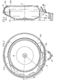
- FIG. 1 and 2 are respectively a front view and a sectional view through an axial plane of a first embodiment of one of the rotary nozzles which can be fitted with a spraying installation according to the present invention.
- Figures 3 and 4 are corresponding views of a second embodiment, Figure 4 being simplified to show only the manifold associated with a rotary nozzle (not shown).
- FIG. 5 is the hydraulic diagram of an embodiment of a mobile spraying installation according to the present invention, allowing the spreading of a constant volume of liquid per unit of surface, despite the variations in its forward speed .
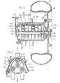
- Figure 6 is a sectional view through an axial plane of the peristaltic pump system which is provided with the embodiment of Figure 5, as well as the drive wheel of this pump system.
- Figure 7 is a section along line VII-VII of Figure 6.
- FIGS. 1 and 2 designates an electric motor, which is housed in a casing 2, and which receives its electrical supply from a cable 3, passing through said casing 2; known means, not shown, are provided to allow the speed of rotation of the electric motor 1 to be precisely adjusted; it may be an adjustment rheostat (not shown) or electronic speed adjustment circuits, well known to those skilled in the art, and which it is therefore not necessary to describe in detail .
- a sleeve 4 for example of molded synthetic material, which is integral with a plate 4a perpendicular to the end of the shaft la, or radial elements, each comprising, on its face opposite to the casing 2, a recess in which is fixed a permanent magnet 5.
- the rotary nozzle 6 has, in this embodiment, the shape of a shallow bowl, the bottom of which is integral with a first cylindrical element 6a, pluggable over the corresponding end of the sleeve 4, as well as a second cylindrical element 6b, with an internal diameter slightly greater than that of the cylindrical surface where the permanent magnets 5 are inscribed; an annular metal ring 7 is fixed between the two cylindrical elements 6a and 6b so that its left face (in FIG. 2) comes into contact with the permanent magnets 5.
- This annular ring 7 is preferably made of soft iron.
- a pump (not shown), for example with a constant volumetric flow rate, takes the liquid to be sprayed from a reservoir and discharges it into the nozzle 8 via a pipe 9.
- the casing 2 which envelops the motor 1 is extended, on the side of the rotary nozzle 6, by a frustoconical collar 2a, the periphery of which is integral with a manifold 10; in the embodiment considered, this collector has the shape of a substantially toroidal gutter, with an almost closed cross section, with the exception of a narrow annular slot, 10a, at the plane P (in phantom in the figure 2), which is perpendicular to the axis of the rotary nozzle, and which passes through the outer edge, 6d, of said nozzle 6.
- a frustoconical collar 2a the periphery of which is integral with a manifold 10; in the embodiment considered, this collector has the shape of a substantially toroidal gutter, with an almost closed cross section, with the exception of a narrow annular slot, 10a, at the plane P (in phantom in the figure 2), which is perpendicular to the axis of the rotary nozzle, and which passes through the outer edge
- the manifold 10 has the shape of a ring sector, of angle equal to (360 ° - 6), so as not to disengage the external edge 6d of the nozzle rotary 6 in the plane P than on the angle G.
- the lowest part, 10b of the annular collector 10, opens above a chute 11, itself leading into a recovery receptacle 12.
- the jet of liquid leaving the nozzle 8 strikes, by spraying, the central part 6c of the rotary nozzle 6; the centrifugal force migrates the droplets of liquid sprayed towards the external edge 6d of the nozzle 6, which projects said droplets substantially in the plane P. All the droplets projected at the level of the annular collector 10 penetrate into its toric gutter by the slot 1Oa then flow by gravity to its lowest part 10b; there, the liquid collected by the collector 10 flows into the receptacle 12 by the chute 11. Only the droplets of sprayed liquid are used for the treatment that the external edge 6d of the rotary nozzle 6 projects at the level of the fixed sector, d angle ⁇ , released by the annular collector 10.
- the liquid collected in the receptacle 12 is returned there into the reservoir (not shown) by the action of a small centrifugal pump 13, which is driven by an electric motor 14, and which discharges said liquid into a return line 15, at the inlet of which a non-return valve 16 is inserted; the latter prevents the liquid contained in the return line 15 from flowing back into the receptacle 12 when the centrifugal pump is stopped.
- the manifold 10 or at least its part located opposite the frustoconical collar 2a, has two elements in the form of ring sector, 10A and 10B, which are mounted so as to be displaceable, concentric with the axis A of the rotary nozzle, one with respect to the other, as well as with respect to the fixed part, 10C of said collector 10, which is integral with the frustoconical collar 2a.
- the lowest part, 10b, of the annular collector 10, and in particular of its element 10A opens above the chute 11 which terminates in the receptacle 12, serving to liquid recovery.
- FIG. 3 there is shown in solid lines the positions of the two movable elements 10A and 10B of the annular collector 10 which correspond to its maximum opening, that is to say at an angle of projection of the liquid close to the angle ⁇ indicated in FIG. 1.
- the positions of the displaceable elements, 10A and 10B, of the annular collector 10, which are indicated by a smaller opening of said collector are indicated in phantom lines. say at a spraying angle ⁇ ', less than the maximum angle 6.
- This arrangement according to the present invention therefore makes it possible to adjust the spraying angle 6 between a maximum value and a minimum value, which can be even less than ⁇ '( Figure 3), and in particular as low as 10 or 15 °.
- FIG. 5 is the hydraulic diagram of a mobile spraying installation according to the present invention, which is equipped with a number of rotary nozzles, 6A to 6X, each provided with an annular collector, 10A to 10X, of the one of the types illustrated in figures 1 to 4 and previously described.
- This installation comprises several pumps, 17A to 17X, which take) e liquid to be sprayed from a container 18, via lines 19 and 20A to 20X; the pumps 17A to 17X respectively deliver the liquid to be sprayed into the lines 9A to 9X, supplying the nozzles (not shown) of the different rotary nozzles, 6A to 6X, via, respectively, expandable sleeves, 21A to 21X, d 'a known type, intended to serve as flow regulators, and control solenoid valves, 22A to 22X.
- Each of the solenoid valves 22A to 22X is of the known type, comprising a rest position (shown in FIG.
- liquid recovery receptacles, 12A to 12X which are respectively associated with the collectors 10A to 10X of the nozzles 6A to 6X are connected to the reservoir 18 respectively by lines 15A to 15X, in which non-return valves, 16A to 16X, as described above with reference to FIG. 2.
- each of the pumps 17A to 17X is a peristaltic pump, produced for example as illustrated in FIG. 7.
- the various peristaltic pumps, 17A to 17X have their rotors, such as 24A, wedged on a common shaft 25, the ends of which are mounted freely rotating in a casing 26, by means of ball bearings or with rollers 27a and 27b; in fact, the bearing 27b is that of an end of an axle 28, the inner face of the housing 26 of which is coupled to the corresponding end of the common shaft 25 via of a freewheel 29, while its outer face to the casing 26 is coupled, in particular by bolts such as 30, with the hub 31 of a drive wheel '32.
- the drive wheel 32 is provided with a pneumatic tire 33, preferably little or not inflated, and the assembly of the casing 26, the shaft 25 and the hub 31 of the wheel 32 is carried, in a manner known per se, by an oscillating arm, so that the tire 33 of said caster 32 is applied, for example by the weight of the assembly, on the periphery of a wheel (not shown) of the mobile spraying installation or of the vehicle which carries it, or which pulls it if it is itself fitted with load-bearing members.
- each peristaltic pump such as 17A or 17B comprises a deformable tube element such as 34A or 34B, for example in extruded synthetic material, with an oval cross section, as visible in FIG. 6; the deformable tube element such as 34A of each pump such as 17A, is placed in a removable cassette, such as 35A, of which said tube element 34A is secured, for example by one end 34A1 (FIG. 7); each of the cassettes 35A has, in section through a plane perpendicular to the common shaft 25, the shape visible in FIG. 7; it is also clearly seen in FIG.
- each cassette such as 35A or 35B has, on the side of the common shaft 25, an opening for the passage of the parts of the rotor, such as 24A, of the corresponding peristaltic pump, which are intended for local crushing of the tube element 34A;
- the rotor such as 24A of each peristaltic pump consists essentially of two discs fixed perpendicular to the common shaft 25 by sleeves threaded on the latter, and by three crushing rollers 24Al to 24A3, mounted between the two rotor discs corresponding 24A, so as to form, beyond the cylindrical surface enveloping the two discs, projections of sufficient width to produce at least partial crushing of the deformable tube element 34A in its part located towards the middle of the corresponding cassette 35A, as shown in FIG. 7.
- the rollers such as 24A1 to 24A3, carried by the rotors, such as 24A, of the various peristaltic pumps crush three times successively the section of the corresponding deformable tube element, 34A, which has for the effect, each time, of driving back by the corresponding roller the quantity of liquid to be sprayed contained in the downstream part of the tube element 34A (relative to the direction of rotation indicated by the arrow f in FIG. 7), in the direction of the outlet pipe 36A (FIG. 7), which for example came from molding with the corresponding cassette 35A.
- each peristaltic pump such as 17A is regulated by the corresponding expandable sleeve, 21A, and a better regularity of spreading over time can be obtained by shifting, for example by 120 degrees, the rollers of the rotors of two pumps successive peristaltics, for example 17A and 17B, as visible in FIG. 6.
- the free wheel 29 prevents the roller 32 from communicating its rotation to the common shaft 25 and that the latter consequently causes the rotors of the different peristaltic pumps.
- each of the deformable tube elements such as 34A must be adapted to the volume of liquid which must be spread per unit of area, regardless of the speed of advance of the spraying installation and consequently the drive wheel 32.
- the replacement of the deformable tube elements such as 34A by tube elements of different cross section is made easy by the fact that it only requires the removal of the corresponding removable cassette, such as 35A, which is optionally integral with one end of the deformable tube element 34A; as visible in FIG.
- the same operations also allow the replacement of one of the deformable tube elements, in the event of deterioration, for example by wear, or obstruction.
- the present invention is not limited to the embodiments previously described. It encompasses all their variants.
- the production of each of the peristaltic pumps is optional, as is their drive with an instantaneous speed always proportional to the speed of advance of the mobile installation.
- the displacement of its two mobile elements 10A and 10B makes it possible not only to vary the spreading angle 6 or ⁇ ', but also the mean direction d spreading, along the periphery of the nozzle - this direction corresponding substantially to the bisector of the angle ⁇ 'in Figure 3 -.
Landscapes
- Engineering & Computer Science (AREA)
- Life Sciences & Earth Sciences (AREA)
- Mechanical Engineering (AREA)
- Insects & Arthropods (AREA)
- Pest Control & Pesticides (AREA)
- Wood Science & Technology (AREA)
- Zoology (AREA)
- Environmental Sciences (AREA)
- Catching Or Destruction (AREA)
- Special Spraying Apparatus (AREA)
Priority Applications (1)
| Application Number | Priority Date | Filing Date | Title |
|---|---|---|---|
| AT81401303T ATE34906T1 (de) | 1981-01-06 | 1981-08-13 | Spruehanlage fuer fluessigkeiten, insbesondere zum behandeln von kulturen oder ackerboden. |
Applications Claiming Priority (2)
| Application Number | Priority Date | Filing Date | Title |
|---|---|---|---|
| FR8100089A FR2497439B1 (fr) | 1981-01-06 | 1981-01-06 | Installation pour la pulverisation d'un liquide de traitement, notamment de traitement des cultures ou des sols |
| FR8100089 | 1981-01-06 |
Publications (3)
| Publication Number | Publication Date |
|---|---|
| EP0055948A2 true EP0055948A2 (de) | 1982-07-14 |
| EP0055948A3 EP0055948A3 (en) | 1982-08-11 |
| EP0055948B1 EP0055948B1 (de) | 1988-06-08 |
Family
ID=9253881
Family Applications (1)
| Application Number | Title | Priority Date | Filing Date |
|---|---|---|---|
| EP81401303A Expired EP0055948B1 (de) | 1981-01-06 | 1981-08-13 | Sprühanlage für Flüssigkeiten, insbesondere zum Behandeln von Kulturen oder Ackerboden |
Country Status (16)
| Country | Link |
|---|---|
| US (1) | US4473188A (de) |
| EP (1) | EP0055948B1 (de) |
| JP (1) | JPS57140666A (de) |
| AR (1) | AR227434A1 (de) |
| AT (1) | ATE34906T1 (de) |
| AU (1) | AU548797B2 (de) |
| BR (1) | BR8105357A (de) |
| CA (1) | CA1181116A (de) |
| DE (1) | DE3176776D1 (de) |
| ES (1) | ES505241A0 (de) |
| FR (1) | FR2497439B1 (de) |
| GR (1) | GR77289B (de) |
| MX (1) | MX160691A (de) |
| OA (1) | OA06884A (de) |
| SU (1) | SU1213970A3 (de) |
| ZA (1) | ZA816006B (de) |
Cited By (2)
| Publication number | Priority date | Publication date | Assignee | Title |
|---|---|---|---|---|
| EP0203964B1 (de) * | 1984-12-05 | 1989-03-15 | BIDON, Daniel | Fliehkraftzerstäuber |
| CN103521388A (zh) * | 2013-10-21 | 2014-01-22 | 中国农业大学 | 一种种子带自动涂胶方法和装置 |
Families Citing this family (19)
| Publication number | Priority date | Publication date | Assignee | Title |
|---|---|---|---|---|
| GB8516638D0 (en) * | 1985-07-01 | 1985-08-07 | P T Chemicals Ltd | Application of particles to substrate |
| GB2183133B (en) * | 1985-11-21 | 1989-11-15 | N Proizv Ob Selskokhozyaistven | Liquid spraying apparatus |
| EP0514610B1 (de) * | 1991-05-23 | 1996-04-24 | Zeus | Verfahren und Anlage für Brandschutz |
| FR2805182B1 (fr) * | 2000-02-21 | 2002-09-20 | Sames Sa | Dispositif de projection de produit de revetement comprenant un element rotatif de pulverisation |
| MD2732C2 (ro) * | 2001-02-23 | 2006-03-31 | Иван СТАЛЕВ | Captator de soluţie al stropitorii cu ventilator |
| WO2004024338A2 (fr) | 2002-09-13 | 2004-03-25 | Sames Technologies | Bol de pulverisation, dispositif de projection incorporant un tel bol et installation de projection incorporant un tel dispositif |
| FR2852868B1 (fr) | 2003-03-27 | 2005-04-29 | Sames Technologies | Bol de pulverisation, dispositif de projection incorporant un tel bol et installation de projection incorporant un tel dispositif |
| DE602005005635T2 (de) * | 2004-02-06 | 2009-05-14 | Sames Technologies | Sprühglocke für einen rotationszerstäuber mit magnetischer befestigung |
| FR2868342B1 (fr) * | 2004-04-02 | 2006-06-02 | Sames Technologies Soc Par Act | Bol de pulverisation, projecteur rotatif incorporant un tel bol et installation de projection incorporant un tel projecteur |
| US8359820B2 (en) * | 2010-01-13 | 2013-01-29 | Dohrmann Daniel R | Ultra-low flow agricultural pump with unobstructed flow path and electronic flow control, tank refill indication, and detection of loss of flow |
| FR2966059B1 (fr) | 2010-10-18 | 2017-04-28 | Exel Ind | Dispositif de projection d'un fluide de traitement, et systeme de pulverisation d'un fluide de traitement comprenant au moins un tel dispositif |
| WO2014052289A2 (en) * | 2012-09-28 | 2014-04-03 | Agco Corporation | Controlled droplet application with directional shroud for limiting application area |
| US9898012B2 (en) * | 2012-09-28 | 2018-02-20 | Agco Corporation | Air assistance and drift reduction technology for controlled droplet applicator |
| US20150258556A1 (en) * | 2012-09-28 | 2015-09-17 | Agco Corporation | Reclamation system for a controlled droplet applicator |
| US9556863B2 (en) | 2014-01-31 | 2017-01-31 | Chapin Manufacturing, Inc. | Peristaltic pump and trailer mounted self pumping sprayer system incorporating same |
| FR3037826B1 (fr) | 2015-06-25 | 2019-09-20 | Pellenc | Unite de pulverisation, module de pulverisation compact comprenant une telle unite et systeme de pulverisation et de pilotage comprenant une pluralite de tels modules |
| FR3037827B1 (fr) | 2015-06-25 | 2017-06-30 | Pellenc Sa | Module de pulverisation compact, systeme de pulverisation et de pilotage d'une pluralite de tels modules et procede de pilotage des modules d'un tel systeme |
| CN111760693A (zh) * | 2020-07-28 | 2020-10-13 | 士商(上海)机械有限公司 | 喷头及喷雾器 |
| CN111760690A (zh) * | 2020-07-28 | 2020-10-13 | 士商(上海)机械有限公司 | 喷雾器 |
Citations (7)
| Publication number | Priority date | Publication date | Assignee | Title |
|---|---|---|---|---|
| FR1501610A (fr) * | 1965-12-17 | 1967-11-10 | Pulvérisateur agricole | |
| US3590503A (en) * | 1969-12-08 | 1971-07-06 | Alfred G Swenson | Spray iron |
| US3807605A (en) * | 1973-04-06 | 1974-04-30 | J Meharry | Sprayer with wheel pump |
| FR2281174A1 (fr) * | 1974-08-07 | 1976-03-05 | Horstine Farmery Ltd | Perfectionnements aux pulverisateurs |
| FR2327822A1 (fr) * | 1975-10-16 | 1977-05-13 | Sloan Albert | Appareil projecteur pulverisateur |
| GB1504868A (en) * | 1974-08-12 | 1978-03-22 | Turbair Ltd | Spraying apparatus |
| FR2403733A1 (fr) * | 1977-09-26 | 1979-04-20 | Tecnoma | Appareil mobile permettant l'epandage de liquides a volume constant par unite de surface |
Family Cites Families (1)
| Publication number | Priority date | Publication date | Assignee | Title |
|---|---|---|---|---|
| GB1505356A (en) * | 1975-02-27 | 1978-03-30 | Horstine Farmery Ltd | Spray apparatus |
-
1981
- 1981-01-06 FR FR8100089A patent/FR2497439B1/fr not_active Expired
- 1981-08-07 ES ES505241A patent/ES505241A0/es active Granted
- 1981-08-10 SU SU813320144A patent/SU1213970A3/ru active
- 1981-08-13 EP EP81401303A patent/EP0055948B1/de not_active Expired
- 1981-08-13 AT AT81401303T patent/ATE34906T1/de not_active IP Right Cessation
- 1981-08-13 DE DE8181401303T patent/DE3176776D1/de not_active Expired
- 1981-08-17 AU AU74254/81A patent/AU548797B2/en not_active Ceased
- 1981-08-19 AR AR286477A patent/AR227434A1/es active
- 1981-08-21 BR BR8105357A patent/BR8105357A/pt not_active IP Right Cessation
- 1981-08-21 OA OA57477A patent/OA06884A/xx unknown
- 1981-08-28 GR GR65891A patent/GR77289B/el unknown
- 1981-08-28 CA CA000384813A patent/CA1181116A/en not_active Expired
- 1981-08-31 ZA ZA816006A patent/ZA816006B/xx unknown
- 1981-09-25 MX MX189349A patent/MX160691A/es unknown
-
1982
- 1982-01-06 JP JP57000462A patent/JPS57140666A/ja active Pending
-
1984
- 1984-02-07 US US06/576,810 patent/US4473188A/en not_active Expired - Lifetime
Patent Citations (7)
| Publication number | Priority date | Publication date | Assignee | Title |
|---|---|---|---|---|
| FR1501610A (fr) * | 1965-12-17 | 1967-11-10 | Pulvérisateur agricole | |
| US3590503A (en) * | 1969-12-08 | 1971-07-06 | Alfred G Swenson | Spray iron |
| US3807605A (en) * | 1973-04-06 | 1974-04-30 | J Meharry | Sprayer with wheel pump |
| FR2281174A1 (fr) * | 1974-08-07 | 1976-03-05 | Horstine Farmery Ltd | Perfectionnements aux pulverisateurs |
| GB1504868A (en) * | 1974-08-12 | 1978-03-22 | Turbair Ltd | Spraying apparatus |
| FR2327822A1 (fr) * | 1975-10-16 | 1977-05-13 | Sloan Albert | Appareil projecteur pulverisateur |
| FR2403733A1 (fr) * | 1977-09-26 | 1979-04-20 | Tecnoma | Appareil mobile permettant l'epandage de liquides a volume constant par unite de surface |
Cited By (3)
| Publication number | Priority date | Publication date | Assignee | Title |
|---|---|---|---|---|
| EP0203964B1 (de) * | 1984-12-05 | 1989-03-15 | BIDON, Daniel | Fliehkraftzerstäuber |
| CN103521388A (zh) * | 2013-10-21 | 2014-01-22 | 中国农业大学 | 一种种子带自动涂胶方法和装置 |
| CN103521388B (zh) * | 2013-10-21 | 2017-02-08 | 中国农业大学 | 一种种子带自动涂胶装置 |
Also Published As
| Publication number | Publication date |
|---|---|
| EP0055948B1 (de) | 1988-06-08 |
| ATE34906T1 (de) | 1988-06-15 |
| FR2497439A1 (fr) | 1982-07-09 |
| OA06884A (fr) | 1983-04-30 |
| EP0055948A3 (en) | 1982-08-11 |
| AU7425481A (en) | 1982-07-15 |
| ES8206958A1 (es) | 1982-08-16 |
| ZA816006B (en) | 1982-09-29 |
| MX160691A (es) | 1990-04-17 |
| ES505241A0 (es) | 1982-08-16 |
| AU548797B2 (en) | 1986-01-02 |
| GR77289B (de) | 1984-09-11 |
| DE3176776D1 (en) | 1988-07-14 |
| US4473188A (en) | 1984-09-25 |
| BR8105357A (pt) | 1983-03-22 |
| CA1181116A (en) | 1985-01-15 |
| JPS57140666A (en) | 1982-08-31 |
| AR227434A1 (es) | 1982-10-29 |
| FR2497439B1 (fr) | 1985-06-07 |
| SU1213970A3 (ru) | 1986-02-23 |
Similar Documents
| Publication | Publication Date | Title |
|---|---|---|
| EP0055948A2 (de) | Sprühanlage für Flüssigkeiten, insbesondere zum Behandeln von Kulturen oder Ackerboden | |
| EP2321483B1 (de) | Rollgerät zur reinigung einer unterwasserfläche mit einem ausrichtbaren antriebsfluss | |
| EP0332552A1 (de) | Verbesserung an Landmaschinen für die Futterernte | |
| EP2235299A2 (de) | Rollgerät zur reinigung einer unterwasserfläche mit teilweise hydraulischem antrieb | |
| FR2514457A1 (fr) | Mecanisme de commande hydraulique | |
| FR2634717A1 (fr) | Appareil pour la manutention de charges lourdes, tel qu'un diable ou fauteuil roulant pour handicapes | |
| FR2466641A1 (fr) | Pompe peristaltique | |
| FR2583997A1 (fr) | Appareil de nettoyage pour un recipient contenant du liquide | |
| FR2541387A1 (fr) | Machine hydraulique ou pneumatique notamment formant pompe ou moteur | |
| CA1034386A (en) | Forage swathing and windrowing machine | |
| WO2017068286A1 (fr) | Appareil nettoyeur de piscine à dispositif de franchissement d'obstacle | |
| LU84425A1 (fr) | Appareil et procede d'application de plastifiants sur un materiau filtrant fibreux | |
| EP0080423A1 (de) | Selbständige Schmiervorrichtung für bewegliche Seile | |
| FR2708173A1 (fr) | Boîtier de distribution pour semoir monograine mécanique. | |
| FR2478156A1 (fr) | Engin automoteur pour l'epandage d'agglomeres, et autres revetements routiers | |
| FR2716835A1 (fr) | Procédé de fabrication d'un tuyau poreux, tuyau poreux obtenu par ledit procédé et utilisation d'un tel tuyau en irrigation. | |
| EP2235293B1 (de) | Rollende vorrichtung zur reinigung einer untergetauchten fläche mit antrieb durch eine angetriebene vorderachsenanordnung und mit teilweise hydraulischem antrieb | |
| CA3193252A1 (fr) | Appareil a tambour de separation d'emballages et matiere y adherant, a impact ecologique ameliore | |
| FR2584648A1 (fr) | Dispositif de guidage notamment pour engin du type robot | |
| FR2881161A1 (fr) | Robot de nettoyage automotique du fond d'une piscine | |
| EP0655402A1 (de) | Tangentialer Abscheider | |
| FR2517925A1 (fr) | Machine a semer les graines d'ail | |
| FR2508349A1 (fr) | Dispositif pulverisateur, en particulier pour le traitement des plantes | |
| FR2630700A1 (de) | ||
| FR2730950A1 (fr) | Dispositif pour fabriquer un tuyau nervure |
Legal Events
| Date | Code | Title | Description |
|---|---|---|---|
| PUAI | Public reference made under article 153(3) epc to a published international application that has entered the european phase |
Free format text: ORIGINAL CODE: 0009012 |
|
| PUAL | Search report despatched |
Free format text: ORIGINAL CODE: 0009013 |
|
| AK | Designated contracting states |
Designated state(s): AT BE CH DE FR GB IT LI LU NL SE |
|
| AK | Designated contracting states |
Designated state(s): AT BE CH DE FR GB IT LI LU NL SE |
|
| 17P | Request for examination filed |
Effective date: 19821022 |
|
| RAP1 | Party data changed (applicant data changed or rights of an application transferred) |
Owner name: TECNOMA |
|
| GRAA | (expected) grant |
Free format text: ORIGINAL CODE: 0009210 |
|
| AK | Designated contracting states |
Kind code of ref document: B1 Designated state(s): AT BE CH DE FR GB IT LI LU NL SE |
|
| PG25 | Lapsed in a contracting state [announced via postgrant information from national office to epo] |
Ref country code: NL Effective date: 19880608 Ref country code: AT Effective date: 19880608 |
|
| REF | Corresponds to: |
Ref document number: 34906 Country of ref document: AT Date of ref document: 19880615 Kind code of ref document: T |
|
| ITF | It: translation for a ep patent filed |
Owner name: STUDIO CONS. BREVETTUALE S.R.L. |
|
| PG25 | Lapsed in a contracting state [announced via postgrant information from national office to epo] |
Ref country code: SE Effective date: 19880630 |
|
| REF | Corresponds to: |
Ref document number: 3176776 Country of ref document: DE Date of ref document: 19880714 |
|
| GBT | Gb: translation of ep patent filed (gb section 77(6)(a)/1977) | ||
| PG25 | Lapsed in a contracting state [announced via postgrant information from national office to epo] |
Ref country code: LU Free format text: LAPSE BECAUSE OF NON-PAYMENT OF DUE FEES Effective date: 19880831 Ref country code: LI Effective date: 19880831 Ref country code: CH Effective date: 19880831 |
|
| NLV1 | Nl: lapsed or annulled due to failure to fulfill the requirements of art. 29p and 29m of the patents act | ||
| PLBE | No opposition filed within time limit |
Free format text: ORIGINAL CODE: 0009261 |
|
| STAA | Information on the status of an ep patent application or granted ep patent |
Free format text: STATUS: NO OPPOSITION FILED WITHIN TIME LIMIT |
|
| REG | Reference to a national code |
Ref country code: CH Ref legal event code: PL |
|
| 26N | No opposition filed | ||
| REG | Reference to a national code |
Ref country code: GB Ref legal event code: 732 |
|
| ITTA | It: last paid annual fee | ||
| PGFP | Annual fee paid to national office [announced via postgrant information from national office to epo] |
Ref country code: BE Payment date: 19980911 Year of fee payment: 18 |
|
| PGFP | Annual fee paid to national office [announced via postgrant information from national office to epo] |
Ref country code: FR Payment date: 19990629 Year of fee payment: 19 |
|
| PGFP | Annual fee paid to national office [announced via postgrant information from national office to epo] |
Ref country code: DE Payment date: 19990827 Year of fee payment: 19 |
|
| PG25 | Lapsed in a contracting state [announced via postgrant information from national office to epo] |
Ref country code: BE Free format text: LAPSE BECAUSE OF NON-PAYMENT OF DUE FEES Effective date: 19990831 |
|
| PGFP | Annual fee paid to national office [announced via postgrant information from national office to epo] |
Ref country code: GB Payment date: 19991130 Year of fee payment: 19 |
|
| BERE | Be: lapsed |
Owner name: TECNOMA Effective date: 19990831 |
|
| PG25 | Lapsed in a contracting state [announced via postgrant information from national office to epo] |
Ref country code: GB Free format text: LAPSE BECAUSE OF NON-PAYMENT OF DUE FEES Effective date: 20000813 |
|
| GBPC | Gb: european patent ceased through non-payment of renewal fee |
Effective date: 20000813 |
|
| PG25 | Lapsed in a contracting state [announced via postgrant information from national office to epo] |
Ref country code: FR Free format text: LAPSE BECAUSE OF NON-PAYMENT OF DUE FEES Effective date: 20010430 |
|
| PG25 | Lapsed in a contracting state [announced via postgrant information from national office to epo] |
Ref country code: DE Free format text: LAPSE BECAUSE OF NON-PAYMENT OF DUE FEES Effective date: 20010501 |
|
| REG | Reference to a national code |
Ref country code: FR Ref legal event code: ST |