EP0055948A2 - Spraying equipment for liquid application, in particular for crop or soil treatments - Google Patents
Spraying equipment for liquid application, in particular for crop or soil treatments Download PDFInfo
- Publication number
- EP0055948A2 EP0055948A2 EP81401303A EP81401303A EP0055948A2 EP 0055948 A2 EP0055948 A2 EP 0055948A2 EP 81401303 A EP81401303 A EP 81401303A EP 81401303 A EP81401303 A EP 81401303A EP 0055948 A2 EP0055948 A2 EP 0055948A2
- Authority
- EP
- European Patent Office
- Prior art keywords
- liquid
- nozzle
- collector
- installation according
- rotary
- Prior art date
- Legal status (The legal status is an assumption and is not a legal conclusion. Google has not performed a legal analysis and makes no representation as to the accuracy of the status listed.)
- Granted
Links
Images


Classifications
-
- A—HUMAN NECESSITIES
- A01—AGRICULTURE; FORESTRY; ANIMAL HUSBANDRY; HUNTING; TRAPPING; FISHING
- A01M—CATCHING, TRAPPING OR SCARING OF ANIMALS; APPARATUS FOR THE DESTRUCTION OF NOXIOUS ANIMALS OR NOXIOUS PLANTS
- A01M7/00—Special adaptations or arrangements of liquid-spraying apparatus for purposes covered by this subclass
- A01M7/0025—Mechanical sprayers
- A01M7/0028—Centrifugal sprayers
-
- B—PERFORMING OPERATIONS; TRANSPORTING
- B05—SPRAYING OR ATOMISING IN GENERAL; APPLYING FLUENT MATERIALS TO SURFACES, IN GENERAL
- B05B—SPRAYING APPARATUS; ATOMISING APPARATUS; NOZZLES
- B05B14/00—Arrangements for collecting, re-using or eliminating excess spraying material
-
- B—PERFORMING OPERATIONS; TRANSPORTING
- B05—SPRAYING OR ATOMISING IN GENERAL; APPLYING FLUENT MATERIALS TO SURFACES, IN GENERAL
- B05B—SPRAYING APPARATUS; ATOMISING APPARATUS; NOZZLES
- B05B3/00—Spraying or sprinkling apparatus with moving outlet elements or moving deflecting elements
- B05B3/02—Spraying or sprinkling apparatus with moving outlet elements or moving deflecting elements with rotating elements
- B05B3/08—Spraying or sprinkling apparatus with moving outlet elements or moving deflecting elements with rotating elements in association with stationary outlet or deflecting elements
- B05B3/082—Spraying or sprinkling apparatus with moving outlet elements or moving deflecting elements with rotating elements in association with stationary outlet or deflecting elements the spraying being effected by centrifugal forces
- B05B3/085—Spraying or sprinkling apparatus with moving outlet elements or moving deflecting elements with rotating elements in association with stationary outlet or deflecting elements the spraying being effected by centrifugal forces in association with sectorial deflectors
Landscapes
- Engineering & Computer Science (AREA)
- Life Sciences & Earth Sciences (AREA)
- Mechanical Engineering (AREA)
- Insects & Arthropods (AREA)
- Pest Control & Pesticides (AREA)
- Wood Science & Technology (AREA)
- Zoology (AREA)
- Environmental Sciences (AREA)
- Catching Or Destruction (AREA)
- Special Spraying Apparatus (AREA)
Abstract
L'invention concerne une installation pour la pulvérisation d'un liquide. Un ajutage alimenté par une pompe et un tuyau 9 projette le liquide à pulvériser sur la partie centrale, 6c, d'une buse rotative 6; un collecteur 10, en forme de secteur d'anneau, est fixé le long du pourtour de la buse rotative 6, sans contact avec elle, de façon à intercepter le liquide projeté sauf dans l'angle ϑ; le liquide intercepté par le collecteur 10 est rassemblé dans un réceptacle 12, et renvoyé dans le réservoir de l'installation. L'invention est applicable notamment pour l'épandage de faibles quantités de liquide par unité de surface, en particulier en agriculture.The invention relates to an installation for spraying a liquid. A nozzle supplied by a pump and a pipe 9 projects the liquid to be sprayed onto the central part, 6c, of a rotary nozzle 6; a manifold 10, in the form of a ring sector, is fixed along the periphery of the rotary nozzle 6, without contact with it, so as to intercept the sprayed liquid except in the angle ϑ; the liquid intercepted by the collector 10 is collected in a receptacle 12, and returned to the installation tank. The invention is applicable in particular for the spreading of small quantities of liquid per unit area, in particular in agriculture.
Description
La présente invention concerne une installation pour la pulvérisation d'un liquide de traitement, notamment de traitement des cultures ou des sols.The present invention relates to an installation for spraying a treatment liquid, in particular for treating crops or soils.
Différents types d'installations mobiles de pulvérisation sont largement utilisés dans l'agriculture, ainsi que pour les traitements arboricoles et viticoles.Different types of mobile spraying installations are widely used in agriculture, as well as for tree and wine treatments.
Ces installations donnent toute satisfaction lorsque le volume de liquide qui doit être épandu par unité de surface est relativement élevé. Certains traitements nécessitent cependant l'épandage d'un volume de liquide relativement faible par unité de surface. Pour réduire le débit du liquide projeté par chaque ajutage d'une telle installation, il suffit évidemment de réduire le diamètre dudit ajutage. Une limite est cependant rapidement atteinte dans ce sens, notamment dans le cas de l'épandage de liquides plus ou moins chargés. Il apparaît alors en effet des risques importants d'obstruction des ajutages.These installations give full satisfaction when the volume of liquid which must be spread per unit of area is relatively high. Some treatments, however, require spreading a relatively small volume of liquid per unit area. To reduce the flow rate of the liquid sprayed by each nozzle of such an installation, it is obviously sufficient to reduce the diameter of said nozzle. A limit is however quickly reached in this direction, in particular in the case of spreading more or less charged liquids. It then appears significant risks of obstruction of the nozzles.
L'installation de pulvérisation selon la présente invention offre l'important avantage de permettre d'épandre de faibles quantités de liquide de traitement.par unité de surface, notamment des quantités inférieures ou égales à 40 litres par hectare.The spraying installation according to the present invention offers the important advantage of making it possible to spread small quantities of treatment liquid per unit area, in particular quantities less than or equal to 40 liters per hectare.
L'installation selon la présente invention comporte au moins une buse rotative, sur la partie centrale de laquelle un ajutage projette le liquide à pulvériser, prélevé par une pompe dans un réservoir, et elle est caractérisée en ce qu'un collecteur en forme de secteur d'anneau, d'angle fixe ou réglable, est fixé le long du pourtour de la buse rotative, sans contact avec elle, de façon à intercepter le liquide pulvérisé dans le secteur correspondant, et que des moyens sont prévus pour renvoyer le liquide rassemblé par le collecteur, dans le réservoir de liquide de traitement.The installation according to the present invention comprises at least one rotary nozzle, on the central part of which a nozzle projects the liquid to be sprayed, withdrawn by a pump into a reservoir, and it is characterized in that a sector-shaped collector ring, fixed or adjustable angle, is fixed along the periphery of the rotary nozzle, without contact with it, so as to intercept the sprayed liquid in the corresponding sector, and that means are provided to return the collected liquid via the collector, in the treatment liquid tank.
On comprend que, en utilisant un même ajutage, il devient possible, grâce à ces dispositions selon la présente invention, de réduire le volume de liquide projeté par chaque buse rotative par unité de temps, simplement par un choix approprié de l'angle couvert par le collecteur en forme de secteur d'anneau, et cela sans qu'il en résulte aucune perte de liquide, puisque les gouttelettes de liquide interceptées par ledit collecteur et rassemblées par lui, sont renvoyées dans le réservoir de liquide de traitement. C'est ainsi notamment que pour un traitement herbicide on pourra utiliser par exemple un collecteur annulaire de 220 degrés, autorisant la pulvérisation seulement sur un angle de 140 degrés, ou bien un collecteur annulaire de 330 degrés, autorisant seulement la pulvérisation dans un angle de 3Q degrés pour des applications localisées.It is understood that, by using the same nozzle, it becomes possible, thanks to these arrangements according to the present invention, to reduce the volume of liquid projected by each rotary nozzle per unit of time, simply by an appropriate choice of the angle covered by the collector in the form of a ring sector, and this without any resulting loss of liquid, since the droplets of liquid intercepted by said collector and collected by it, are returned to the reservoir of treatment liquid. Thus, for example, for a herbicide treatment, it is possible to use, for example, an annular manifold of 220 degrees, allowing spraying only at an angle of 140 degrees, or else an annular manifold of 330 degrees, allowing only spraying at an angle of 3Q degrees for localized applications.
Il est bien entendu possible d'utiliser la même installation de pulvérisation avec des collecteurs d'angles différents ou réglables, dont la mise en place, l'enlèvement ou le réglage peuvent être rendus très aisés, par des moyens mécaniques simples. Cependant, dans une forme de réalisation préférée de l'invention, le collecteur comporte deux éléments, chacun en forme de secteur d'anneau, dont l'un au moins peut être monté de façon à être déplaçable coaxialement à la buse rotative correspondante, l'autre élément du collecteur pouvant être fixe. Un tel collecteur, en deux éléments, permet d'ajuster, par exemple manuellement, de façon très aisée, l'angle du secteur d'anneau formé par ses deux éléments annulaires, entre une valeur minimale et une valeur maximale, qui peut être peu inférieure à 360 degrés, pour permettre des applications localiséesIt is of course possible to use the same spraying installation with angle collectors different or adjustable, including the establishment, removal or adjustment can be made very easy, by simple mechanical means. However, in a preferred embodiment of the invention, the collector comprises two elements, each in the form of a ring sector, at least one of which can be mounted so as to be movable coaxially with the corresponding rotary nozzle, l other collector element which can be fixed. Such a collector, in two elements, makes it possible to adjust, for example manually, very easily, the angle of the ring sector formed by its two annular elements, between a minimum value and a maximum value, which can be little less than 360 degrees, to allow localized applications
Un réglage du diamètre des gouttelettes de liquide pulvérisé peut être aussi obtenu, selon une autre caractéristique de l'invention, en faisant entraîner chaque buse rotative par un moteur à vitesse réglable, par exemple un moteur électrique, associé à un rhéostat de réglage de sa vitesse. Une telle disposition autorise ainsi à régler le nombre de gouttelettes de liquide épandues par centimètre carré.An adjustment of the diameter of the droplets of sprayed liquid can also be obtained, according to another characteristic of the invention, by causing each rotary nozzle to be driven by a motor with adjustable speed, for example an electric motor, associated with a rheostat for adjusting its speed. Such an arrangement thus allows the number of droplets of liquid spread per square centimeter to be regulated.
La présente invention permet donc de réaliser des installations mobiles de pulvérisation à plusieurs buses rotatives, pour l'agriculture et notamment pour les cultures basses. Les mêmes installations mobiles selon la présente invention peuvent être facilement adaptées pour les traitements arboricoles et viticoles en prévoyant une ou plusieurs souffleries, produisant un courant d'air dirigé de façon à entraîner le liquide pulvérisé par chaque buse rotative en direction des plantes à traiter.The present invention therefore makes it possible to produce mobile spraying installations with several rotary nozzles, for agriculture and in particular for low crops. The same mobile installations according to the present invention can be easily adapted for arboricultural and viticultural treatments by providing one or more blowers, producing a current of air directed so as to entrain the liquid sprayed by each rotary nozzle towards the plants to be treated.
On sait que les installations mobiles de pulvérisation de ce genre épandent un volume de liquide sensiblement constant par unité de temps, si bien que les variations de leur vitesse d'avancement se traduisent par des variations correspondantes du volume de liquide épandu par unité de surface.It is known that mobile spraying installations of this kind spread a volume of liquid substantially constant per unit of time, so that the variations in their speed of advance result in corresponding variations in the volume of liquid spread per unit of area.
Une forme de réalisation de la présente invention offre cependant l'important avantage de permettre l'épandage d'un volume constant de liquide par unité de surface malgré les variations de la vitesse d'avancement de l'installation mobile de pulvérisation. Cette forme de réalisation est caractérisée en ce que les buses rotatives sont alimentées respectivement par des pompes péristaltiques, dont les rotors sont calés sur un arbre commun, accouplé au moyeu d'une roulette d'entrainement, par exemple une roulette à bandage pneumatique peu ou pas gonflé, appliqué sur la périphérie d'une roue de l'installation mobile ou de son véhicule porteur et/ou tracteur.An embodiment of the present invention, however, offers the important advantage of allowing the spreading of a constant volume of liquid per unit area despite variations in the speed of advance of the mobile spraying installation. This embodiment is characterized in that the rotary nozzles are supplied respectively by peristaltic pumps, the rotors of which are wedged on a common shaft, coupled to the hub of a drive wheel, for example a tire wheel with little or no tire. not inflated, applied to the periphery of a wheel of the mobile installation or of its carrier vehicle and / or tractor.
Dans la mesure où il ne se produit pratiquement aucun glissement entre la roulette d'entrainement, à bandage pneumatique peu gonflé, et la roue de l'installation ou du véhicule correspondant, sur la périphérie de laquelle ladite roulette est appliquée, ainsi qu'entre cette roue et le sol, cette disposition selon la présente invention assure une quasi proportionnalité entre le débit volumétrique de chaque pompe péristaltique et la vitesse d'avancement de l'installation, d'où résulte un volume d'épandage pratiquement constant par unité de distance parcourue par l'installation mobile, et, par suite, par unité de surface traitée.Insofar as there is practically no slippage between the drive wheel, with slightly inflated pneumatic tire, and the wheel of the installation or of the corresponding vehicle, on the periphery of which said wheel is applied, as well as between this wheel and the ground, this arrangement according to the present invention ensures almost proportionality between the volumetric flow rate of each peristaltic pump and the speed of advance of the installation, resulting in a practically constant spreading volume per unit of distance traveled by the mobile installation, and therefore by unit of surface treated.
A titre d'exemple, on a décrit ci-dessous et illustré schématiquement au dessin annexé plusieurs formes'de réalisation de l'invention.
Les figures 1 et 2 sont respectivement une vue de face et une vue en coupe par un plan axial d'une première forme de réalisation de l'une des buses rotatives dont peut être équipée une installation de pulvérisation selon la présente invention. Les figures 3 et 4 sont des vues correspondantes d'une seconde forme de réalisation, la figure 4 étant simplifiée pour montrer seulement le collecteur associé à une buse rotative (non représentée). La figure 5 est le schéma hydraulique d'une forme de réalisation d'une installation mobile de pulvérisation selon la présente invention, permettant l'épandage d'un volume constant de liquide par unité de surface, malgré les variations de sa vitesse d'avancement. La figure 6 est une vue en coupe par un plan axial du système de pompes péristaltiques dont est pourvue la forme de réalisation de la figure 5, ainsi que de la roulette d'entraînement de ce système de pompes. La figure 7 est une coupe suivant la ligne VII-VII de la figure 6.By way of example, several embodiments of the invention have been described below and illustrated diagrammatically in the accompanying drawing.
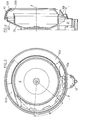
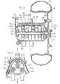
Figures 1 and 2 are respectively a front view and a sectional view through an axial plane of a first embodiment of one of the rotary nozzles which can be fitted with a spraying installation according to the present invention. Figures 3 and 4 are corresponding views of a second embodiment, Figure 4 being simplified to show only the manifold associated with a rotary nozzle (not shown). FIG. 5 is the hydraulic diagram of an embodiment of a mobile spraying installation according to the present invention, allowing the spreading of a constant volume of liquid per unit of surface, despite the variations in its forward speed . Figure 6 is a sectional view through an axial plane of the peristaltic pump system which is provided with the embodiment of Figure 5, as well as the drive wheel of this pump system. Figure 7 is a section along line VII-VII of Figure 6.
Sur les figures 1 et 2, 1 désigne un moteur électrique, qui est logé dans un carter 2, et qui reçoit son alimentation électrique d'un câble 3, traversant ledit carter 2; des moyens connus, non représentés, sont prévus pour permettre d'ajuster avec précision la vitesse de rotation du moteur électrique 1; il peut s'agir d'un rhéostat de réglage (non représenté) ou de circuits électroniques de réglage de la vitesse, bien connus de l'homme de l'art, et qu'il n'est donc pas nécessaire de décrire en détail. Sur le bout, 1a, de l'arbre du moteur 1 qui sort du carter 2 est assujetti un manchon 4, par exemple en matière synthétique moulée, qui est solidaire d'un plateau 4a perpendiculaire au bout d'arbre la, ou d'éléments radiaux, comportant chacun, sur sa face opposée au carter 2, un évidement dans lequel est assujetti un aimant permanent 5. La buse rotative 6 présente, dans cette forme de réalisation, la forme d'une cuvette peu profonde, dont le fond est solidaire d'un premier élément cylindrique 6a, enfichable par dessus l'extrémité correspondante du manchon 4, ainsi que d'un second élément cylindrique 6b, de diamètre intérieur un peu supérieur à celui de la surface cylindrique où sont inscrits les aimants permanents 5; une bague métallique annulaire 7 est assujettie entre les deux éléments cylindriques 6a et 6b de manière que sa face gauche (sur la figure 2) vienne au contact des aimants permanents 5. Cette bague annulaire 7 est constituée de préférence en fer doux. Le dispositif qui vient d'être décrit assure l'accouplement de la buse rotative 6 avec le bout la de l'arbre du moteur 1, dans des conditions qui permettent une extraction et une remise en place très rapides de ladite buse rotative 6. En regard de la partie centrale, 6c, de la face de la buse rotative 6, opposée au moteur 1 débouche un ajutage cylindrique 8; une pompe (non représentée), par exemple à débit volumétrique constant, prélève le liquide à pulvériser dans un réservoir et le refoule dans l'ajutage 8 par l'intermédiaire d'une conduite 9.In FIGS. 1 and 2, 1 designates an electric motor, which is housed in a casing 2, and which receives its electrical supply from a cable 3, passing through said casing 2; known means, not shown, are provided to allow the speed of rotation of the
Selon la présente invention, le carter 2 qui enveloppe le moteur 1 est prolongé, du côté de la buse rotative 6, par une collerette tronconique 2a, dont le pourtour est solidaire d'un collecteur 10; dans la forme de réalisation considérée, ce collecteur a la forme d'une gouttière sensiblement torique, à section transversale presque fermée, à l'exception d'une fente annulaire étroite, 10a, au niveau du plan P (en traits mixtes sur la figure 2), qui est perpendiculaire à l'axe de la buse rotative, et qui passe par le bord externe, 6d, de ladite buse 6. Comme visible sur la figure 1, le collecteur 10 a la forme d'un secteur d'anneau, d'angle égal à (360° - 6), de façon à ne dégager le bord externe 6d de la buse rotative 6 dans le plan P que sur l'angle G. La partie la plus basse, 10b du collecteur annulaire 10, s'ouvre au-dessus d'une goulotte 11, conduisant elle-même dans un réceptacle de récupération 12.According to the present invention, the casing 2 which envelops the
Le jet de liquide sortant de l'ajutage 8 heurte, en se pulvérisant, la partie centrale 6c de la buse rotative 6; la force centrifuge fait migrer les gouttelettes de liquide pulvérisé vers le bord externe 6d de la buse 6, qui projette lesdites gouttelettes sensiblement dans le plan P. Toutes les gouttelettes projetées au niveau du collecteur annulaire 10 pénètrent dans sa gouttière torique par la fente 1Oa puis s'écoulent par gravité jusqu'à sa partie la plus basse 10b; là, le liquide rassemblé par le collecteur 10 s'écoule dans le réceptacle 12 par la goulotte 11. Seules sont utilisées pour le traitement les gouttelettes de liquide pulvérisé que le bord externe 6d de la buse rotative 6 projette au niveau du secteur fixe, d'angle θ, dégagé par le collecteur annulaire 10. Le liquide rassemblé dans le réceptacle 12 y est renvoyé dans le réservoir (non représenté) par l'action d'une petite pompe centrifuge 13, qui est entraînée par un moteur électrique 14, et qui refoule ledit liquide dans une conduite de retour 15, à l'entrée de laquelle est inséré un clapet anti-retour 16; ce dernier évite que, à l'arrêt de la pompe centrifuge 13, le liquide contenu dans la conduite de retour 15 ne reflue dans le réceptacle 12.The jet of liquid leaving the nozzle 8 strikes, by spraying, the central part 6c of the
Dans la variante illustrée schématiquement et partiellement sur les figures 3 et 4, le collecteur 10, ou tout au moins sa partie située à l'opposé de la collerette tronconique 2a, comporte deux éléments en forme de secteur d'anneau, 10A et 10B, qui sont montés de façon à être déplaçables, concentriquement à l'axe A de la buse rotative, l'un par rapport à l'autre, ainsi que par rapport à la partie fixe, 10C dudit collecteur 10, qui est solidaire de la collerette tronconique 2a. Comme dans la forme de réalisation des figures 1 et 2, la partie la plus basse,10b, du collecteur annulaire 10, et notamment de son élément 10A s'ouvre au-dessus de la goulotte 11 qui aboutit dans le réceptacle 12, servant à la récupération du liquide. Sur la figure 3, on a représenté en traits pleins les positions des deux éléments mobiles 10A et 10B du collecteur annulaire 10 qui correspondent à son ouverture maximale, c'est-à-dire à un angle de projection du liquide voisin de l'angle θ indiqué sur la figure 1. Sur la même figure 3, on a indiqué en traits mixtes les positions des éléments déplaçables, 10A et 10B, du collecteur annulaire 10, qui correspondent à une plus faible ouverture dudit collecteur, c'est-à-dire à un angle de pulvérisation θ', inférieur à l'angle maximal 6. Cette disposition selon la présente invention permet donc d'ajuster l'angle 6 de pulvérisation entre une valeur maximale et une valeur minimale, qui peut être encore inférieure à θ' (figure 3), et notamment aussi faible que 10 ou 15°. Des valeurs aussi faibles de l'angle de pulvérisation θ permettent évidemment d'obtenir des volumes d'épandage notablement inférieurs à 20 litres/hectare. On rappelle que le réglage de la vitesse du moteur électrique 1 (figure 2), permet de régler le diamètre des gouttelettes de liquide pulvérisé.In the variant illustrated schematically and partially in Figures 3 and 4, the
La figure 5 est le schéma hydraulique d'une installation mobile de pulvérisation selon la présente invention, qui est équipée d'un certain nombre de buses rotatives, 6A à 6X, munies chacune d'un collecteur annulaire, 10A à 10X, de l'un des types illustrés sur les figures 1 à 4 et précédemment décrits. Cette installation comporte plusieurs pompes, 17A à 17X, qui prélèvent )e liquide à pulvériser dans un récipient 18, par l'intermédiaire de conduites 19 et 20A à 20X; les pompes 17A à 17X refoulent respectivement le liquide à pulvériser dans les conduites 9A à 9X, alimentant les ajutages (non représentés) des différentes buses rotatives, 6A à 6X, par l'intermédiaire, respectivement, de manchettes dilatables, 21A à 21X, d'un type connu, destinées à servir de régulateurs de débit, et d'électrovannes de commande, 22A à 22X. Chacune des électrovannes 22A à 22X est du type connu, comportant une position de repos (représentée sur la figure 5), dans laquelle la pompe correspondante, par exemple 17A, débite dans une conduite commune de retour, 23, aboutissant au réservoir 18, et une position de travail, dans laquelle la pompe correspondante débite dans la conduite 9A précédemment mentionnée. Les réceptacles de récupération du liquide, 12A à 12X, qui sont associés respectivement aux collecteurs 10A à 10X des buses 6A à 6X sont raccordés au réservoir 18 respectivement par des conduites 15A à 15X, dans lesquelles sont insérés des clapets anti-retour, 16A à 16X, comme on l'a décrit précédemment à propos de la figure 2.FIG. 5 is the hydraulic diagram of a mobile spraying installation according to the present invention, which is equipped with a number of rotary nozzles, 6A to 6X, each provided with an annular collector, 10A to 10X, of the one of the types illustrated in figures 1 to 4 and previously described. This installation comprises several pumps, 17A to 17X, which take) e liquid to be sprayed from a
Dans la forme de réalisation de l'invention, dont la figure 5 reproduit le schéma hydraulique, chacune des pompes 17A à 17X, associées respectivement aux buses rotatives 6A à 6X, est une pompe péristaltique, réalisée par exemple comme illustré sur la figure 7. D'autre part, les différentes pompes péristaltiques, 17A à 17X, ont leurs rotors, tel que 24A, calés sur un arbre commun 25, dont les extrémités sont montées librement tournantes dans un carter 26, par l'intermédiaire de paliers à billes ou à rouleaux 27a et 27b; en fait, le palier 27b est celui d'un bout d'axe 28, dont la face intérieure au carter 26 est accouplée à l'extrémité correspondante de l'arbre commun 25 par l'intermédiaire d'une roue libre 29, tandis que sa face extérieure au carter 26 est accouplée, notamment par des boulons tels que 30, avec le moyeu 31 d'une roulette d'entraînement'32. Dans la forme de réalisation considérée, la roulette d'entrainement 32 est pourvue d'un bandage pneumatique 33, de préférence peu ou pas gonflé, et l'ensemble du carter 26, de l'arbre 25 et du moyeu 31 de la roulette 32 est porté, de façon connue en soi, par un bras , oscillant, de telle manière que le bandage 33 de ladite roulette 32 soit appliqué, par exemple par le poids de l'ensemble, sur la périphérie d'une roue (non représentée) de l'installation mobile de pulvérisation ou bien du véhicule qui la porte, ou qui la tire si elle est elle-même munie d'organes porteurs.In the embodiment of the invention, the hydraulic diagram of which in FIG. 5 reproduces, each of the
Selon la présente invention, chaque pompe péristaltique telle que 17A ou 17B comporte un élément de tube déformable tel que 34A ou 34B, par exemple en matière synthétique extrudée, à section droite ovale, comme visible sur la figure 6; l'élément de tube déformable tel que 34A de chaque pompe telle que 17A, est placé dans une cassette amovible, telle que 35A, dont ledit élément de tube 34A est solidaire, par exemple par une extrémité 34A1 (figure 7); chacune des cassettes 35A présente, en section par un plan perpendiculaire à l'arbre commun 25, la forme visible sur la figure 7; on voit clairement en outre sur la figure 6 que chaque cassette telle que 35A ou 35B présente, du côté de l'arbre commun 25, une ouverture pour le passage des parties du rotor, tel que 24A, de la pompe péristaltique correspondante, qui sont destinées à l'écrasement local de l'élément de tube 34A; dans l'exemple de réalisation illustré, le rotor tel que 24A de chaque pompe péristaltique est constitué essentiellement par deux disques fixés perpendiculairement à l'arbre commun 25 par des manchons enfilés sur ce dernier, et par trois galets d'écrasement 24Al à 24A3, montés entre les deux disques du rotor correspondant 24A, de façon à former, au-delà de la surface cylindrique enveloppant les deux disques, des saillies de largeur suffisante pour produire l'écrasement au moins partiel de l'élément de tube déformable 34A dans sa partie située vers le milieu de la cassette correspondante 35A, comme visible sur la figure 7.According to the present invention, each peristaltic pump such as 17A or 17B comprises a deformable tube element such as 34A or 34B, for example in extruded synthetic material, with an oval cross section, as visible in FIG. 6; the deformable tube element such as 34A of each pump such as 17A, is placed in a removable cassette, such as 35A, of which said
Lorsque l'installation mobile de pulvérisation selon la présente invention progresse, par exemple à la suite de son véhicule tracteur (non représenté), la roue de l'installation ou de ce véhicule sur la périphérie de laquelle est appliqué le bandage pneumatique 33 de la roulette d'entraînement 32 entraîne cette dernière en rotation, et le sens de la roue libre 29 a été choisi tel que le moyeu 31 de ladite roulette 32 entraine en rotation l'arbre commun 25 sur lequel sont calés les rotors de toutes les pompes péristaltiques. A chaque tour de la roulette 32, les galets tels que 24A1 à 24A3, portés par les rotors, tels que 24A, des différentes pompes péristaltiques, écrasent trois fois successivement la section de l'élément de tube déformable correspondant, 34A, ce qui a pour effet, à chaque fois, de faire refouler par le galet correspondant la quantité de liquide à pulvériser contenue dans la partie aval de l'élément de tube 34A (par rapport au sens de rotation indiqué par la flèche f sur la figure 7), en direction de la tubulure de sortie 36A (figure 7), qui est par exemple venue de moulage avec la cassette correspondante 35A. Le débit de chaque pompe péristaltique telle que 17A est régulé par la manchette dilatable correspondante, 21A, et une meilleure régularité de l'épandage au cours du temps peut être obtenue en décalant, par exemple de 120 degrés, les galets des rotors de deux pompes péristaltiques successives, par exemple 17A et 17B, comme visible sur la figure 6.When the mobile spraying installation according to the present invention progresses, for example following its towing vehicle (not shown), the wheel of the installation or of this vehicle on the periphery of which is applied the
En l'absence de glissement entre, d'une part la roulette 32 et la roue sur la périphérie de laquelle elle est appliquée, et, d'autre part, entre cette dernière, et le sol, la vitesse de rotation instantanée des rotors tels que 24A des pompes péristaltiques telles que 17A est proportionnelle à la vitesse d'avancement de l'installation mobile de pulvérisation, ce qui assure au moins une constance approximative du volume de liquide épandu par unité de surface, malgré les variations de la vitesse d'avancement, qui sont inévitables en particu- lier sur les terrains irréguliers.In the absence of sliding between, on the one hand the
Si l'installation mobile de pulvérisation précédemment décrite est déplacée vers l'arrière, la roue libre 29 évite que la roulette 32 ne communique sa rotation à l'arbre commun 25 et que celui-ci n'entraîne par conséquent en rotation les rotors des différentes pompes péristaltiques.If the mobile spraying installation described above is moved rearward, the
Bien entendu, la section transversale de chacun des éléments de tube déformables tel que 34A doit être adaptée au volume de liquide qui doit être épandu par unité de surface, quelle que soit la vitesse d'avancement de l'installation de pulvérisation et par suite de la roulette d'entrainement 32. Le remplacement des éléments de tube déformables tels que 34A par des éléments de tube de section transversale différente est rendu aisé par le fait qu'il nécessite seulement l'enlèvement de la cassette amovible correspondante, telle que 35A, dont est éventuellement solidaire l'une des extrémités de l'élément de tube déformable 34A; comme visible sur la figure 6, l'enlèvement d'une ou plusieurs des cassettes telles que 35A nécessite seulement le dévissage des boulons tels que 37, ce qui permet ensuite de faire pivoter la plaque supérieure de fermeture 38 autour de l'axe 38a, dans le sens de la flèche F, et enfin de dégager lesdites cassettes par enlèvement de la plaque 40.Of course, the cross section of each of the deformable tube elements such as 34A must be adapted to the volume of liquid which must be spread per unit of area, regardless of the speed of advance of the spraying installation and consequently the
Les mêmes opérations permettent aussi le remplacement de l'un des éléments de tube déformables, en cas de détérioration, par exemple par usure, ou d'obstruction.The same operations also allow the replacement of one of the deformable tube elements, in the event of deterioration, for example by wear, or obstruction.
La présente invention n'est pas limitée aux formes de réalisation précédemment décrites. Elle englobe toutes leurs variantes. La réalisation de chacune des pompes péristaltiques est matière à option, de même que leur entraînement avec une vitesse instantanée toujours proportionnelle à la vitesse d'avancement de l'installation mobile. Dans le cas du collecteur illustré sur les figures 3 et 4, et précédemment décrit, le déplacement de ses deux éléments mobiles 10A et 10B permet non seulement de faire varier l'angle d'épandage 6 ou θ', mais aussi la direction moyenne d'épandage, le long du pourtour de la buse - cette direction correspondant sensiblement à la bissectrice de l'angle θ' sur la figure 3 -. Même dans le cas d'un collecteur définissant un angle fixe, 6, de pulvérisation (figure 1), il est possible de rendre la partie 10A (figure 2) de ce collecteur déplaçable coaxialement à la buse 6 de manière à pouvoir déplacer la direction moyenne de pulvérisation le long du pourtour de ladite buse. Bien entendu, dans le cas du collecteur réglable illustré sur les figures 3 et 4, l'un de ses deux éléments, 10A ou 10B, peut être fixe, et, éventuellement, solidaire de sa partie fixe 10C, le réglage étant alors obtenu en déplaçant seulement son autre élément, 10B ou 10A.The present invention is not limited to the embodiments previously described. It encompasses all their variants. The production of each of the peristaltic pumps is optional, as is their drive with an instantaneous speed always proportional to the speed of advance of the mobile installation. In the case of the manifold illustrated in FIGS. 3 and 4, and previously described, the displacement of its two
Claims (10)
Priority Applications (1)
| Application Number | Priority Date | Filing Date | Title |
|---|---|---|---|
| AT81401303T ATE34906T1 (en) | 1981-01-06 | 1981-08-13 | SPRAYING UNIT FOR LIQUIDS, PARTICULARLY FOR TREATMENT OF CROPS OR ARABLE SOIL. |
Applications Claiming Priority (2)
| Application Number | Priority Date | Filing Date | Title |
|---|---|---|---|
| FR8100089 | 1981-01-06 | ||
| FR8100089A FR2497439B1 (en) | 1981-01-06 | 1981-01-06 | INSTALLATION FOR THE SPRAYING OF A TREATMENT LIQUID, IN PARTICULAR FOR TREATING CROPS OR SOILS |
Publications (3)
| Publication Number | Publication Date |
|---|---|
| EP0055948A2 true EP0055948A2 (en) | 1982-07-14 |
| EP0055948A3 EP0055948A3 (en) | 1982-08-11 |
| EP0055948B1 EP0055948B1 (en) | 1988-06-08 |
Family
ID=9253881
Family Applications (1)
| Application Number | Title | Priority Date | Filing Date |
|---|---|---|---|
| EP81401303A Expired EP0055948B1 (en) | 1981-01-06 | 1981-08-13 | Spraying equipment for liquid application, in particular for crop or soil treatments |
Country Status (16)
| Country | Link |
|---|---|
| US (1) | US4473188A (en) |
| EP (1) | EP0055948B1 (en) |
| JP (1) | JPS57140666A (en) |
| AR (1) | AR227434A1 (en) |
| AT (1) | ATE34906T1 (en) |
| AU (1) | AU548797B2 (en) |
| BR (1) | BR8105357A (en) |
| CA (1) | CA1181116A (en) |
| DE (1) | DE3176776D1 (en) |
| ES (1) | ES505241A0 (en) |
| FR (1) | FR2497439B1 (en) |
| GR (1) | GR77289B (en) |
| MX (1) | MX160691A (en) |
| OA (1) | OA06884A (en) |
| SU (1) | SU1213970A3 (en) |
| ZA (1) | ZA816006B (en) |
Cited By (2)
| Publication number | Priority date | Publication date | Assignee | Title |
|---|---|---|---|---|
| EP0203964B1 (en) * | 1984-12-05 | 1989-03-15 | BIDON, Daniel | Centrifugal spray apparatus |
| CN103521388A (en) * | 2013-10-21 | 2014-01-22 | 中国农业大学 | Automatic gluing method and device of seed belt |
Families Citing this family (19)
| Publication number | Priority date | Publication date | Assignee | Title |
|---|---|---|---|---|
| GB8516638D0 (en) * | 1985-07-01 | 1985-08-07 | P T Chemicals Ltd | Application of particles to substrate |
| FR2590186B1 (en) * | 1985-11-21 | 1988-02-05 | N Proizv Ob Tulatschermet | LIQUID SPRAYING DEVICE |
| EP0514610B1 (en) * | 1991-05-23 | 1996-04-24 | Zeus | Method and apparatus for area fire protection |
| FR2805182B1 (en) * | 2000-02-21 | 2002-09-20 | Sames Sa | COATING PRODUCT SPRAYING DEVICE COMPRISING A ROTATING SPRAYING ELEMENT |
| MD2732C2 (en) * | 2001-02-23 | 2006-03-31 | Иван СТАЛЕВ | Solution catcher of the blower sprayer |
| FR2852868B1 (en) | 2003-03-27 | 2005-04-29 | Sames Technologies | SPRAYING BOWL, PROJECTION DEVICE INCORPORATING SUCH A BOWL AND PROJECTION INSTALLATION INCORPORATING SUCH A DEVICE |
| WO2004024338A2 (en) | 2002-09-13 | 2004-03-25 | Sames Technologies | Spray bowl, discharge device comprising one such bowl and discharge installation comprising one such device |
| FR2868342B1 (en) * | 2004-04-02 | 2006-06-02 | Sames Technologies Soc Par Act | SPRAYING BOWL, ROTARY PROJECTOR INCORPORATING SUCH A BOWL AND PROJECTION INSTALLATION INCORPORATING SUCH A PROJECTOR |
| ATE390207T1 (en) * | 2004-02-06 | 2008-04-15 | Sames Technologies | SPRAY BELL FOR A ROTARY ATOMIZER WITH MAGNETIC MOUNTING |
| WO2011088273A2 (en) * | 2010-01-13 | 2011-07-21 | Dohrmann Daniel R | Ultra-low flow agricultural pump with unobstructed flow path and electronic flow control, tank refill indication, and detection of loss of flow |
| FR2966059B1 (en) | 2010-10-18 | 2017-04-28 | Exel Ind | DEVICE FOR PROJECTING A TREATMENT FLUID, AND SYSTEM FOR SPRAYING A TREATMENT FLUID COMPRISING AT LEAST ONE SUCH DEVICE |
| US20150224521A1 (en) * | 2012-09-28 | 2015-08-13 | Agco Corporation | Controlled droplet application with directional shroud for limiting application area |
| WO2014052351A1 (en) * | 2012-09-28 | 2014-04-03 | Agco Corporation | Air assistance and drift reduction technology for controlled droplet applicator |
| US20150258556A1 (en) * | 2012-09-28 | 2015-09-17 | Agco Corporation | Reclamation system for a controlled droplet applicator |
| US9556863B2 (en) | 2014-01-31 | 2017-01-31 | Chapin Manufacturing, Inc. | Peristaltic pump and trailer mounted self pumping sprayer system incorporating same |
| FR3037827B1 (en) | 2015-06-25 | 2017-06-30 | Pellenc Sa | COMPACT SPRAY MODULE, SYSTEM FOR SPRAYING AND CONTROLLING A PLURALITY OF SUCH MODULES AND METHOD FOR CONTROLLING THE MODULES OF SUCH A SYSTEM |
| FR3037826B1 (en) | 2015-06-25 | 2019-09-20 | Pellenc | SPRAY UNIT, COMPACT SPRAY MODULE COMPRISING SUCH A UNIT AND SPRAY AND PILOTAGE SYSTEM COMPRISING A PLURALITY OF SUCH MODULES |
| CN111760690A (en) * | 2020-07-28 | 2020-10-13 | 士商(上海)机械有限公司 | Sprayer with a spray tube |
| CN111760693A (en) * | 2020-07-28 | 2020-10-13 | 士商(上海)机械有限公司 | Spray head and sprayer |
Citations (7)
| Publication number | Priority date | Publication date | Assignee | Title |
|---|---|---|---|---|
| FR1501610A (en) * | 1965-12-17 | 1967-11-10 | Agricultural sprayer | |
| US3590503A (en) * | 1969-12-08 | 1971-07-06 | Alfred G Swenson | Spray iron |
| US3807605A (en) * | 1973-04-06 | 1974-04-30 | J Meharry | Sprayer with wheel pump |
| FR2281174A1 (en) * | 1974-08-07 | 1976-03-05 | Horstine Farmery Ltd | IMPROVEMENTS FOR SPRAYERS |
| FR2327822A1 (en) * | 1975-10-16 | 1977-05-13 | Sloan Albert | SPRAYING PROJECTOR UNIT |
| GB1504868A (en) * | 1974-08-12 | 1978-03-22 | Turbair Ltd | Spraying apparatus |
| FR2403733A1 (en) * | 1977-09-26 | 1979-04-20 | Tecnoma | MOBILE DEVICE ALLOWING THE SPREADING OF LIQUIDS AT CONSTANT VOLUME PER UNIT OF SURFACE |
Family Cites Families (1)
| Publication number | Priority date | Publication date | Assignee | Title |
|---|---|---|---|---|
| GB1505356A (en) * | 1975-02-27 | 1978-03-30 | Horstine Farmery Ltd | Spray apparatus |
-
1981
- 1981-01-06 FR FR8100089A patent/FR2497439B1/en not_active Expired
- 1981-08-07 ES ES505241A patent/ES505241A0/en active Granted
- 1981-08-10 SU SU813320144A patent/SU1213970A3/en active
- 1981-08-13 EP EP81401303A patent/EP0055948B1/en not_active Expired
- 1981-08-13 DE DE8181401303T patent/DE3176776D1/en not_active Expired
- 1981-08-13 AT AT81401303T patent/ATE34906T1/en not_active IP Right Cessation
- 1981-08-17 AU AU74254/81A patent/AU548797B2/en not_active Ceased
- 1981-08-19 AR AR286477A patent/AR227434A1/en active
- 1981-08-21 BR BR8105357A patent/BR8105357A/en not_active IP Right Cessation
- 1981-08-21 OA OA57477A patent/OA06884A/en unknown
- 1981-08-28 CA CA000384813A patent/CA1181116A/en not_active Expired
- 1981-08-28 GR GR65891A patent/GR77289B/el unknown
- 1981-08-31 ZA ZA816006A patent/ZA816006B/en unknown
- 1981-09-25 MX MX189349A patent/MX160691A/en unknown
-
1982
- 1982-01-06 JP JP57000462A patent/JPS57140666A/en active Pending
-
1984
- 1984-02-07 US US06/576,810 patent/US4473188A/en not_active Expired - Lifetime
Patent Citations (7)
| Publication number | Priority date | Publication date | Assignee | Title |
|---|---|---|---|---|
| FR1501610A (en) * | 1965-12-17 | 1967-11-10 | Agricultural sprayer | |
| US3590503A (en) * | 1969-12-08 | 1971-07-06 | Alfred G Swenson | Spray iron |
| US3807605A (en) * | 1973-04-06 | 1974-04-30 | J Meharry | Sprayer with wheel pump |
| FR2281174A1 (en) * | 1974-08-07 | 1976-03-05 | Horstine Farmery Ltd | IMPROVEMENTS FOR SPRAYERS |
| GB1504868A (en) * | 1974-08-12 | 1978-03-22 | Turbair Ltd | Spraying apparatus |
| FR2327822A1 (en) * | 1975-10-16 | 1977-05-13 | Sloan Albert | SPRAYING PROJECTOR UNIT |
| FR2403733A1 (en) * | 1977-09-26 | 1979-04-20 | Tecnoma | MOBILE DEVICE ALLOWING THE SPREADING OF LIQUIDS AT CONSTANT VOLUME PER UNIT OF SURFACE |
Cited By (3)
| Publication number | Priority date | Publication date | Assignee | Title |
|---|---|---|---|---|
| EP0203964B1 (en) * | 1984-12-05 | 1989-03-15 | BIDON, Daniel | Centrifugal spray apparatus |
| CN103521388A (en) * | 2013-10-21 | 2014-01-22 | 中国农业大学 | Automatic gluing method and device of seed belt |
| CN103521388B (en) * | 2013-10-21 | 2017-02-08 | 中国农业大学 | Automatic gluing device of seed belt |
Also Published As
| Publication number | Publication date |
|---|---|
| EP0055948A3 (en) | 1982-08-11 |
| CA1181116A (en) | 1985-01-15 |
| SU1213970A3 (en) | 1986-02-23 |
| JPS57140666A (en) | 1982-08-31 |
| ES8206958A1 (en) | 1982-08-16 |
| ZA816006B (en) | 1982-09-29 |
| FR2497439A1 (en) | 1982-07-09 |
| US4473188A (en) | 1984-09-25 |
| ATE34906T1 (en) | 1988-06-15 |
| BR8105357A (en) | 1983-03-22 |
| FR2497439B1 (en) | 1985-06-07 |
| AR227434A1 (en) | 1982-10-29 |
| AU7425481A (en) | 1982-07-15 |
| EP0055948B1 (en) | 1988-06-08 |
| DE3176776D1 (en) | 1988-07-14 |
| AU548797B2 (en) | 1986-01-02 |
| ES505241A0 (en) | 1982-08-16 |
| GR77289B (en) | 1984-09-11 |
| OA06884A (en) | 1983-04-30 |
| MX160691A (en) | 1990-04-17 |
Similar Documents
| Publication | Publication Date | Title |
|---|---|---|
| EP0055948A2 (en) | Spraying equipment for liquid application, in particular for crop or soil treatments | |
| EP2321483B1 (en) | Rolling apparatus for cleaning a submerged surface with an orientable driving flow | |
| EP0332552B1 (en) | Improvement for agricultural harvesting machines | |
| EP2235299A2 (en) | Rolling apparatus for cleaning a submerged surface with partially hydraulic drive | |
| FR2514457A1 (en) | HYDRAULIC CONTROL MECHANISM | |
| FR2634717A1 (en) | APPARATUS FOR THE HANDLING OF HEAVY LOADS, SUCH AS A DEVIL OR WHEELCHAIR FOR HANDICAPS | |
| FR2583997A1 (en) | CLEANING APPARATUS FOR A CONTAINER CONTAINING LIQUID | |
| FR2541387A1 (en) | HYDRAULIC OR PNEUMATIC MACHINE, IN PARTICULAR FORMING PUMP OR ENGINE | |
| CA1034386A (en) | Forage swathing and windrowing machine | |
| EP0026704A1 (en) | Peristaltic pump | |
| WO2017068286A1 (en) | Swimming pool cleaning apparatus comprising an obstacle clearance device | |
| LU84425A1 (en) | APPARATUS AND METHOD FOR APPLYING PLASTICIZERS TO FIBROUS FILTER MATERIAL | |
| EP0080423A1 (en) | Self-contained lubrication assembly for moving cables | |
| FR2708173A1 (en) | Distribution box for mechanical seeding machine. | |
| FR2478156A1 (en) | AUTOMOTIVE ENGINE FOR SPREADING AGGLOMERES, AND OTHER ROAD COVERINGS | |
| FR2716835A1 (en) | Method of manufacturing a porous pipe, porous pipe obtained by said method and use of such pipe in irrigation. | |
| EP2235293B1 (en) | Rolling submerged-surface cleaning apparatus driven by a driven front axle assembly with partially hydraulic drive also | |
| CA3193252A1 (en) | Apparatus with drum for separating packagings and material adhering thereto, with improved environmental impact | |
| EP1875017B1 (en) | Robot for automatic cleaning of the floor of a swimming pool | |
| FR2549909A1 (en) | ROLLER PUMP WITH PERISTALTIC MOVEMENT AND ROTOR FOR THIS PUMP | |
| EP0655402A1 (en) | Tangential separator | |
| FR2468302A2 (en) | Irrigator with hose reel - has positioning wheels holding races against supporting rollers to prevent axial movement | |
| FR2508349A1 (en) | SPRAY DEVICE, ESPECIALLY FOR PLANT TREATMENT | |
| FR2630700A1 (en) | ||
| FR3126197A1 (en) | Gun for ejecting a spoke in a hole in the hub of a spoked wheel |
Legal Events
| Date | Code | Title | Description |
|---|---|---|---|
| PUAI | Public reference made under article 153(3) epc to a published international application that has entered the european phase |
Free format text: ORIGINAL CODE: 0009012 |
|
| PUAL | Search report despatched |
Free format text: ORIGINAL CODE: 0009013 |
|
| AK | Designated contracting states |
Designated state(s): AT BE CH DE FR GB IT LI LU NL SE |
|
| AK | Designated contracting states |
Designated state(s): AT BE CH DE FR GB IT LI LU NL SE |
|
| 17P | Request for examination filed |
Effective date: 19821022 |
|
| RAP1 | Party data changed (applicant data changed or rights of an application transferred) |
Owner name: TECNOMA |
|
| GRAA | (expected) grant |
Free format text: ORIGINAL CODE: 0009210 |
|
| AK | Designated contracting states |
Kind code of ref document: B1 Designated state(s): AT BE CH DE FR GB IT LI LU NL SE |
|
| PG25 | Lapsed in a contracting state [announced via postgrant information from national office to epo] |
Ref country code: NL Effective date: 19880608 Ref country code: AT Effective date: 19880608 |
|
| REF | Corresponds to: |
Ref document number: 34906 Country of ref document: AT Date of ref document: 19880615 Kind code of ref document: T |
|
| ITF | It: translation for a ep patent filed |
Owner name: STUDIO CONS. BREVETTUALE S.R.L. |
|
| PG25 | Lapsed in a contracting state [announced via postgrant information from national office to epo] |
Ref country code: SE Effective date: 19880630 |
|
| REF | Corresponds to: |
Ref document number: 3176776 Country of ref document: DE Date of ref document: 19880714 |
|
| GBT | Gb: translation of ep patent filed (gb section 77(6)(a)/1977) | ||
| PG25 | Lapsed in a contracting state [announced via postgrant information from national office to epo] |
Ref country code: LU Free format text: LAPSE BECAUSE OF NON-PAYMENT OF DUE FEES Effective date: 19880831 Ref country code: LI Effective date: 19880831 Ref country code: CH Effective date: 19880831 |
|
| NLV1 | Nl: lapsed or annulled due to failure to fulfill the requirements of art. 29p and 29m of the patents act | ||
| PLBE | No opposition filed within time limit |
Free format text: ORIGINAL CODE: 0009261 |
|
| STAA | Information on the status of an ep patent application or granted ep patent |
Free format text: STATUS: NO OPPOSITION FILED WITHIN TIME LIMIT |
|
| REG | Reference to a national code |
Ref country code: CH Ref legal event code: PL |
|
| 26N | No opposition filed | ||
| REG | Reference to a national code |
Ref country code: GB Ref legal event code: 732 |
|
| ITTA | It: last paid annual fee | ||
| PGFP | Annual fee paid to national office [announced via postgrant information from national office to epo] |
Ref country code: BE Payment date: 19980911 Year of fee payment: 18 |
|
| PGFP | Annual fee paid to national office [announced via postgrant information from national office to epo] |
Ref country code: FR Payment date: 19990629 Year of fee payment: 19 |
|
| PGFP | Annual fee paid to national office [announced via postgrant information from national office to epo] |
Ref country code: DE Payment date: 19990827 Year of fee payment: 19 |
|
| PG25 | Lapsed in a contracting state [announced via postgrant information from national office to epo] |
Ref country code: BE Free format text: LAPSE BECAUSE OF NON-PAYMENT OF DUE FEES Effective date: 19990831 |
|
| PGFP | Annual fee paid to national office [announced via postgrant information from national office to epo] |
Ref country code: GB Payment date: 19991130 Year of fee payment: 19 |
|
| BERE | Be: lapsed |
Owner name: TECNOMA Effective date: 19990831 |
|
| PG25 | Lapsed in a contracting state [announced via postgrant information from national office to epo] |
Ref country code: GB Free format text: LAPSE BECAUSE OF NON-PAYMENT OF DUE FEES Effective date: 20000813 |
|
| GBPC | Gb: european patent ceased through non-payment of renewal fee |
Effective date: 20000813 |
|
| PG25 | Lapsed in a contracting state [announced via postgrant information from national office to epo] |
Ref country code: FR Free format text: LAPSE BECAUSE OF NON-PAYMENT OF DUE FEES Effective date: 20010430 |
|
| PG25 | Lapsed in a contracting state [announced via postgrant information from national office to epo] |
Ref country code: DE Free format text: LAPSE BECAUSE OF NON-PAYMENT OF DUE FEES Effective date: 20010501 |
|
| REG | Reference to a national code |
Ref country code: FR Ref legal event code: ST |