EP0055346B1 - Font module and receptacle therefor for use in a matrix printer - Google Patents
Font module and receptacle therefor for use in a matrix printer Download PDFInfo
- Publication number
- EP0055346B1 EP0055346B1 EP81108544A EP81108544A EP0055346B1 EP 0055346 B1 EP0055346 B1 EP 0055346B1 EP 81108544 A EP81108544 A EP 81108544A EP 81108544 A EP81108544 A EP 81108544A EP 0055346 B1 EP0055346 B1 EP 0055346B1
- Authority
- EP
- European Patent Office
- Prior art keywords
- module
- receptacle
- storage module
- font storage
- end surface
- Prior art date
- Legal status (The legal status is an assumption and is not a legal conclusion. Google has not performed a legal analysis and makes no representation as to the accuracy of the status listed.)
- Expired
Links
Images


Classifications
-
- B—PERFORMING OPERATIONS; TRANSPORTING
- B41—PRINTING; LINING MACHINES; TYPEWRITERS; STAMPS
- B41J—TYPEWRITERS; SELECTIVE PRINTING MECHANISMS, i.e. MECHANISMS PRINTING OTHERWISE THAN FROM A FORME; CORRECTION OF TYPOGRAPHICAL ERRORS
- B41J5/00—Devices or arrangements for controlling character selection
- B41J5/30—Character or syllable selection controlled by recorded information
- B41J5/44—Character or syllable selection controlled by recorded information characterised by storage of recorded information
Definitions
- the present invention relates to matrix printers and more specifically to a font storage module containing retrievably stored font information for printing patterns such as characters, and a receptacle for receiving such a module.
- Replaceable devices that incorporate retrievable data or computer instructions are known.
- Replaceable circuit boards including font storage for a matrix printer are also known.
- the replacement has been inconvenient particularly for persons unfamiliar with "hook up" of electrical assemblies.
- the replaceable devices have tended to have projecting contacts that are vulnerable to being caught and damaged causing them to require special handling and storage.
- a cooperating font storage module for use in a matrix printer comprising the features which form the subject-matter of claim 1.
- Another object of the invention is a receptable for receiving such a module comprising the features which form the subject-matter of claim 7.
- a font module 8 for use in a matrix printer includes a circuit board 10 with an information storage device 12 mounted thereto.
- the storage device 12 is preferably a semiconductor read-only-memory (ROM) with logic for receiving information requests and responding by interrogating the stored information and outputting that information as is well known in the art.
- ROM read-only-memory
- Stored in the storage device 12 is information representing patterns for marks to be formed during printing operations. Preferably, address data and timing signals as well as operating power are multiplexed to require four input/ output terminals 14.
- terminals 14 may be varied within reasonable limits without departing from the invention.
- conducting paths 18 printed on the circuit board 10 extend to corresponding self supporting conductor pins 20 having mounted at their ends a set of contact pads 22 (see also Fig. 2) which are preferably plated with a high quality contact material such as gold.
- the above-described electrical assembly 23 is designed to be conveniently handled by an operator, as have been the type elements of traditional typewriters.
- a housing 24, that is electrically insulating, is formed around the electrical assembly 23 preferably by a single molding operation but a two section housing could be used and would have some advantages in facilitating the positioning of the electrical assembly 23 within said housing.
- the housing 24 is generally rectangular in shape having a first major surface 26 at what will be referred to as the rear of the module 8 and a second major surface 28 which is generally coextensive with and parallel to said first major surface and faces in the opposite direction.
- An insertion end surface 30 is preferably oriented to be perpendicular to the major surfaces 26 and 28.
- Two narrow side surfaces 25 and 27 connect the major surfaces 26 and 28 and are perpendicular to the insertion end surface 30.
- a handle section 32 is arranged to be opposite the insertion end surface 30 and includes a legend surface 34 that is angled relative to the major surfaces 26 and 28.
- a cutaway portion 36 to the lower rear of the handle section 32 is adapted to accommodate a hood portion of a receptacle, discussed below, and is defined by rectilinear surfaces 38 and 40.
- the contact pads 22 are exposed in narrow recesses defined by slanted window-frame like surfaces 42. Preferably, the contact pads 22 are aligned in a row parallel to the insertion end surface 30.
- Asymmetry to prevent reversed insertion of the font module 8 is achieved by forming notches 44 in one of the major surfaces 26 and 28 extending vertically from the insertion end surface 30.
- the cross sectional profile of the module 8 preferably presents no projections in progressing vertically from the insertion end surface 30 for the full intended insertion distance so as to permit a close fitting receptacle to be used.
- two notches are formed at either side of the front facing major surface 28.
- Camming to provide a special insertion motion and latching are provided for by at least one but preferably two shoulder sections 46 that include a camming surface 48 that slopes from the first major surface 26 toward the second major surface 28 and away from the insertion end surface.
- Each camming surface 48 terminates in a latching edge 50 as a result of a sharply angled cutaway defining a latching surface 54 that preferably is parallel to the major surfaces 26 and 28.
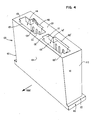
- a receptacle 100 has a body portion 102 that includes a sloped front wall 104, a rear wall 106 and a pair of side walls 108 and 110.
- a center wall 112 serves to define two cavities 114 and 114' (comparable elements are identified using primes and will not be discussed separately) for individually receiving the modules 8 (see Figs. 1 and 2).
- a bottom panel 118 extends to provide a mounting flange 122 and receives a floor panel 120 for the cavity 114 which may be bonded in place.
- a cover panel 124 defines an aperture 126 for receiving the module 8 and is shaped with corresponding asymmetry respective of the insertion end surface 30 to prevent reversed insertions.
- the ribs 130 are spaced to accommodate the width of the major surface 28.
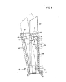
- a leaf spring 132 rises from the floor 120 of the cavity 114 and provides resilient resistance to insertion of one of the modules 8.
- Spring contacts 134 (only one of four is shown for the single cavity 114) are mounted in elongate grooves 136 (see also Fig. 5) on the inside of the rear wall 106 and extend forward of the wall at a position corresponding to the position of the pads 22 of the module 8 when in operative position (shown in Fig. 5 as a full line view, the initial insertion position being indicated in Phantom).
- the sloped front wall 104 and the sloped front surface 150 of a hook 152 define a gap that receives the font module 8 which enters easily until resisted by the spring 132.
- a hood section 160 (see Figs. 3 and 4) of the top surface 124 of receptacle 100 extends over the contacts 134 and is shaped to enter the cutaway portion 36 of the font module 8.
- Removal of the font module 8 is conveniently achieved by a downward pressure to move the edge 50 below the reference edge 154 and a light forward flick to permit an ejection powered by the resilient spring 132.
Landscapes
- Accessory Devices And Overall Control Thereof (AREA)
- Coupling Device And Connection With Printed Circuit (AREA)
Applications Claiming Priority (2)
| Application Number | Priority Date | Filing Date | Title |
|---|---|---|---|
| US06/221,694 US4388010A (en) | 1980-12-31 | 1980-12-31 | Font module for matrix printer |
| US221694 | 1980-12-31 |
Publications (3)
| Publication Number | Publication Date |
|---|---|
| EP0055346A2 EP0055346A2 (en) | 1982-07-07 |
| EP0055346A3 EP0055346A3 (en) | 1983-06-22 |
| EP0055346B1 true EP0055346B1 (en) | 1986-02-05 |
Family
ID=22828939
Family Applications (1)
| Application Number | Title | Priority Date | Filing Date |
|---|---|---|---|
| EP81108544A Expired EP0055346B1 (en) | 1980-12-31 | 1981-10-20 | Font module and receptacle therefor for use in a matrix printer |
Country Status (8)
| Country | Link |
|---|---|
| US (1) | US4388010A (enExample) |
| EP (1) | EP0055346B1 (enExample) |
| JP (2) | JPS57146386A (enExample) |
| AU (1) | AU541438B2 (enExample) |
| BR (1) | BR8107760A (enExample) |
| CA (1) | CA1169295A (enExample) |
| DE (1) | DE3173732D1 (enExample) |
| ES (1) | ES269740Y (enExample) |
Families Citing this family (37)
| Publication number | Priority date | Publication date | Assignee | Title |
|---|---|---|---|---|
| JPS57153306A (en) * | 1981-03-17 | 1982-09-21 | Matsushita Electric Works Ltd | Sequence controller |
| JPS58211476A (ja) * | 1982-06-02 | 1983-12-08 | Canon Inc | 電子印字装置 |
| JPS5957768A (ja) * | 1982-09-29 | 1984-04-03 | Toshiba Corp | 印字装置 |
| JPS5960522A (ja) * | 1982-09-30 | 1984-04-06 | Canon Inc | 電子機器 |
| JPS59115869A (ja) * | 1982-12-23 | 1984-07-04 | Tokyo Electric Co Ltd | ドツトプリンタ |
| USD286053S (en) | 1983-09-29 | 1986-10-07 | International Business Machines Corporation | Data memory module |
| JPS6097432A (ja) * | 1983-11-01 | 1985-05-31 | Fuji Xerox Co Ltd | 文字発生装置 |
| JPS60123099A (ja) * | 1983-12-08 | 1985-07-01 | キヤノン株式会社 | 増設用電子機器 |
| DE3504937C2 (de) * | 1984-02-14 | 1994-04-14 | Canon Kk | Elektronische Einrichtung mit einer Druckvorrichtung |
| DE3509206C2 (de) * | 1984-03-15 | 1994-09-22 | Canon Kk | Schriftart-Auswahlvorrichtung |
| US5020022A (en) * | 1984-03-15 | 1991-05-28 | Canon Kabushiki Kaisha | Printing apparatus for use with a detachable memory |
| FR2566327B1 (fr) * | 1984-06-25 | 1989-06-02 | Epson Corp | Imprimante |
| JPS6158750A (ja) * | 1984-08-31 | 1986-03-26 | Toshiba Corp | メモリ装置 |
| JPS6158749A (ja) * | 1984-08-31 | 1986-03-26 | Toshiba Corp | 印字処理装置 |
| IT1180106B (it) * | 1984-11-05 | 1987-09-23 | Olivetti & Co Spa | Circuito per il pilotaggio dei motori elettrici di selezione tabulazione ed interlinea di una macchina per scrivere elettronica |
| JPH0678011B2 (ja) * | 1984-11-27 | 1994-10-05 | 株式会社リコー | プリンタ |
| US4636022A (en) * | 1985-03-11 | 1987-01-13 | Thomas & Betts Corporation | Cassette connector |
| USD289765S (en) | 1985-03-13 | 1987-05-12 | Nec Corporation | Font cartridge for computer output printers |
| US4730947A (en) * | 1985-08-19 | 1988-03-15 | Citizen Watch Co., Ltd. | Printer having a control circuit section of cassette type |
| USD296787S (en) | 1985-11-14 | 1988-07-19 | Nec Corporation | Font cartridge for computer output printers |
| JPS6337970A (ja) * | 1986-08-01 | 1988-02-18 | Alps Electric Co Ltd | ドツトプリンタ |
| FR2603721B1 (fr) * | 1986-09-05 | 1991-04-19 | Pitney Bowes Inc | Imprimante de securite pour l'impression de signes postaux et son procede d'utilisation |
| JP2832710B2 (ja) * | 1987-01-07 | 1998-12-09 | 沖電気工業 株式会社 | プリンタ |
| JP2685184B2 (ja) * | 1987-07-06 | 1997-12-03 | キヤノン株式会社 | 印刷装置 |
| US5171092A (en) * | 1987-07-06 | 1992-12-15 | Canon Kabushiki Kaisha | Printing apparatus that stores externally supplied fonts |
| USD313426S (en) | 1987-10-23 | 1991-01-01 | Hewlett-Packard Company | Printer font cartridge |
| US4992827A (en) * | 1987-12-28 | 1991-02-12 | Canon Kabushiki Kaisha | Image forming apparatus |
| US4966562A (en) * | 1988-09-06 | 1990-10-30 | The Ohio Bell Telephone Company | Single slot repeater mounting |
| US4908637A (en) * | 1989-01-30 | 1990-03-13 | Acer Incorporated | Font cartridge adapter |
| US5206736A (en) * | 1990-09-28 | 1993-04-27 | Xerox Corporation | Font storage management and control |
| US5167013A (en) * | 1990-09-28 | 1992-11-24 | Xerox Corporation | User definable font substitutions with equivalency indicators |
| US5122073A (en) * | 1990-12-24 | 1992-06-16 | Ncr Corporation | Connector for coupling a plurality of devices to a circuit in a printer |
| US5145400A (en) * | 1991-12-30 | 1992-09-08 | Ag Communication Systems Corporation | Spring contacts for substrate connection |
| US5310128A (en) * | 1993-02-08 | 1994-05-10 | Pitney Bowes Inc. | Tape storage apparatus for mailing machine |
| TW395594U (en) * | 1998-11-13 | 2000-06-21 | Acer Peripherals Inc | Output input connecting device |
| FR2974030B1 (fr) * | 2011-04-12 | 2021-03-05 | Evolis | Imprimante de cartes plastiques |
| KR20150117138A (ko) * | 2014-04-09 | 2015-10-19 | 삼성전자주식회사 | 옵션 키트 어댑터 및 이를 채용한 화상형성장치 |
Family Cites Families (12)
| Publication number | Priority date | Publication date | Assignee | Title |
|---|---|---|---|---|
| US3702464A (en) * | 1971-05-04 | 1972-11-07 | Ibm | Information card |
| GB1473868A (en) * | 1973-10-23 | 1977-05-18 | Olivetti & Co Spa | Electrothermal printers |
| US3964591A (en) * | 1975-06-10 | 1976-06-22 | International Business Machines Corporation | Font selection system |
| JPS5258335A (en) * | 1975-11-07 | 1977-05-13 | Tokyo Electric Co Ltd | Program extending method by rom cassette system |
| NL7613358A (nl) * | 1976-12-01 | 1978-06-05 | Philips Nv | Besturingsinrichting voor een matrixdrukker. |
| US4095791A (en) * | 1976-08-23 | 1978-06-20 | Fairchild Camera And Instrument Corp. | Cartridge programmable video game apparatus |
| US4149027A (en) * | 1977-05-27 | 1979-04-10 | Atari, Inc. | TV game cartridge and method |
| US4216522A (en) * | 1977-06-06 | 1980-08-05 | Texas Instruments Incorporated | Interchangeable module for integrated circuits |
| US4227238A (en) * | 1977-09-28 | 1980-10-07 | Nippon Gakki Seizo Kabushiki Kaisha | Mounting and electrical connection means for operation unit for electric devices |
| JPS54109088U (enExample) * | 1978-01-20 | 1979-08-01 | ||
| DE2850378A1 (de) * | 1978-11-21 | 1980-05-29 | Olympia Werke Ag | Einrichtung zur eingabe von funktionssteuerbefehlen an einer schreib- oder aehnlichen daten schreibenden bueromaschine |
| DE2900438A1 (de) * | 1979-01-08 | 1980-07-17 | Olympia Werke Ag | Anordnung an einer schreib- o.ae. daten schreibenden bueromaschine mit austauschbaren summen-typentraegern |
-
1980
- 1980-12-31 US US06/221,694 patent/US4388010A/en not_active Expired - Lifetime
-
1981
- 1981-10-09 CA CA000387650A patent/CA1169295A/en not_active Expired
- 1981-10-20 EP EP81108544A patent/EP0055346B1/en not_active Expired
- 1981-10-20 DE DE8181108544T patent/DE3173732D1/de not_active Expired
- 1981-11-11 AU AU77372/81A patent/AU541438B2/en not_active Ceased
- 1981-11-20 ES ES1981269740U patent/ES269740Y/es not_active Expired
- 1981-11-27 BR BR8107760A patent/BR8107760A/pt not_active IP Right Cessation
- 1981-12-08 JP JP56196393A patent/JPS57146386A/ja active Granted
-
1982
- 1982-01-26 JP JP57009621A patent/JPS57146387A/ja active Granted
Also Published As
| Publication number | Publication date |
|---|---|
| JPS57146386A (en) | 1982-09-09 |
| AU541438B2 (en) | 1985-01-10 |
| ES269740U (es) | 1983-08-01 |
| DE3173732D1 (en) | 1986-03-20 |
| EP0055346A2 (en) | 1982-07-07 |
| ES269740Y (es) | 1984-02-16 |
| JPS57146387A (en) | 1982-09-09 |
| JPS623502B2 (enExample) | 1987-01-26 |
| BR8107760A (pt) | 1982-08-31 |
| EP0055346A3 (en) | 1983-06-22 |
| JPS623503B2 (enExample) | 1987-01-26 |
| CA1169295A (en) | 1984-06-19 |
| US4388010A (en) | 1983-06-14 |
| AU7737281A (en) | 1982-07-08 |
Similar Documents
| Publication | Publication Date | Title |
|---|---|---|
| EP0055346B1 (en) | Font module and receptacle therefor for use in a matrix printer | |
| KR0162089B1 (ko) | 접속장치 | |
| US5795190A (en) | Connector having ground plate for PC cards | |
| EP0748527B1 (en) | Card edge connector providing non-simultaneous electrical connections | |
| EP0804820B1 (en) | Connector including pcb latching and ejection mechanism | |
| KR0156027B1 (ko) | 스위치 수단을 갖춘 집적회로 팩 커넥터 장치 | |
| EP0829117B1 (en) | Surface mounted electrical connector | |
| US4537454A (en) | Intercard-extraction means | |
| US6004155A (en) | Card connector | |
| EP0360630A3 (en) | High density backplane connector | |
| US6592407B2 (en) | High-speed card edge connector | |
| EP0030763A2 (en) | Zero insertion force connector for integrated circuit package | |
| US5267872A (en) | Card-edge connector apparatus and method of molding the same | |
| GB2163305A (en) | Backplane connector | |
| US4716497A (en) | Printed circuit board module | |
| US7445497B2 (en) | Electrical connector | |
| US7261578B2 (en) | Card connector | |
| US4355856A (en) | Low insertion force connector using non-noble metal contact plating | |
| US4795362A (en) | Circuit connector for use with printed wiring board | |
| US7438556B2 (en) | Electrical interconnection between multiple printed circuit boards | |
| US5967813A (en) | Ejector mechanism for card bus connector | |
| EP0214762A3 (en) | Cassette connector with pivot mechanism | |
| CN209775847U (zh) | 墨盒 | |
| US5224865A (en) | Sliding wedge electrical connector | |
| JPH0237119B2 (enExample) |
Legal Events
| Date | Code | Title | Description |
|---|---|---|---|
| PUAI | Public reference made under article 153(3) epc to a published international application that has entered the european phase |
Free format text: ORIGINAL CODE: 0009012 |
|
| 17P | Request for examination filed |
Effective date: 19811020 |
|
| AK | Designated contracting states |
Designated state(s): BE CH DE FR GB IT LI NL SE |
|
| PUAL | Search report despatched |
Free format text: ORIGINAL CODE: 0009013 |
|
| AK | Designated contracting states |
Designated state(s): BE CH DE FR GB IT LI NL SE |
|
| GRAA | (expected) grant |
Free format text: ORIGINAL CODE: 0009210 |
|
| AK | Designated contracting states |
Designated state(s): BE CH DE FR GB IT LI NL SE |
|
| ET | Fr: translation filed | ||
| REF | Corresponds to: |
Ref document number: 3173732 Country of ref document: DE Date of ref document: 19860320 |
|
| ITF | It: translation for a ep patent filed | ||
| PLBE | No opposition filed within time limit |
Free format text: ORIGINAL CODE: 0009261 |
|
| STAA | Information on the status of an ep patent application or granted ep patent |
Free format text: STATUS: NO OPPOSITION FILED WITHIN TIME LIMIT |
|
| 26N | No opposition filed | ||
| REG | Reference to a national code |
Ref country code: FR Ref legal event code: GC |
|
| REG | Reference to a national code |
Ref country code: CH Ref legal event code: PUE Owner name: LEXMARK INTERNATIONAL, INC. |
|
| REG | Reference to a national code |
Ref country code: GB Ref legal event code: 732 |
|
| REG | Reference to a national code |
Ref country code: FR Ref legal event code: TP |
|
| ITPR | It: changes in ownership of a european patent |
Owner name: CESSIONE;LEXMARK INTERNATIONAL INC. |
|
| NLS | Nl: assignments of ep-patents |
Owner name: LEXMARK INTERNATIONAL, INC. TE LEXINGTON, KENTUCKY |
|
| ITPR | It: changes in ownership of a european patent |
Owner name: PEGNO;J.P. MORGAN DELAWARE |
|
| REG | Reference to a national code |
Ref country code: CH Ref legal event code: PVP Owner name: J.P. MORGAN DELAWARE |
|
| ITTA | It: last paid annual fee | ||
| EAL | Se: european patent in force in sweden |
Ref document number: 81108544.8 |
|
| PGFP | Annual fee paid to national office [announced via postgrant information from national office to epo] |
Ref country code: SE Payment date: 19950913 Year of fee payment: 15 Ref country code: NL Payment date: 19950913 Year of fee payment: 15 Ref country code: FR Payment date: 19950913 Year of fee payment: 15 Ref country code: CH Payment date: 19950913 Year of fee payment: 15 |
|
| PGFP | Annual fee paid to national office [announced via postgrant information from national office to epo] |
Ref country code: DE Payment date: 19950925 Year of fee payment: 15 Ref country code: BE Payment date: 19950925 Year of fee payment: 15 |
|
| PGFP | Annual fee paid to national office [announced via postgrant information from national office to epo] |
Ref country code: GB Payment date: 19950927 Year of fee payment: 15 |
|
| PG25 | Lapsed in a contracting state [announced via postgrant information from national office to epo] |
Ref country code: GB Effective date: 19961020 |
|
| PG25 | Lapsed in a contracting state [announced via postgrant information from national office to epo] |
Ref country code: SE Effective date: 19961021 |
|
| PG25 | Lapsed in a contracting state [announced via postgrant information from national office to epo] |
Ref country code: LI Effective date: 19961031 Ref country code: CH Effective date: 19961031 Ref country code: BE Effective date: 19961031 |
|
| BERE | Be: lapsed |
Owner name: LEXMARK INTERNATIONAL INC. Effective date: 19961031 |
|
| PG25 | Lapsed in a contracting state [announced via postgrant information from national office to epo] |
Ref country code: NL Effective date: 19970501 |
|
| GBPC | Gb: european patent ceased through non-payment of renewal fee |
Effective date: 19961020 |
|
| REG | Reference to a national code |
Ref country code: CH Ref legal event code: PL |
|
| PG25 | Lapsed in a contracting state [announced via postgrant information from national office to epo] |
Ref country code: FR Effective date: 19970630 |
|
| NLV4 | Nl: lapsed or anulled due to non-payment of the annual fee |
Effective date: 19970501 |
|
| PG25 | Lapsed in a contracting state [announced via postgrant information from national office to epo] |
Ref country code: DE Effective date: 19970701 |
|
| EUG | Se: european patent has lapsed |
Ref document number: 81108544.8 |
|
| REG | Reference to a national code |
Ref country code: FR Ref legal event code: ST |